3D printing — formally, additive manufacturing (AM) — builds physical parts from a digital model by joining material layer upon layer, rather than cutting it away from a block or forcing it into a mold.1 What began as a prototyping tool in the 1980s now produces end-use hardware in polymers, metals, ceramics, and elastomers across aerospace, medicine, energy, and consumer products.2,3 This guide explains how 3D printing works, walks through all seven process families recognized by the international standard, and shows how to choose a process by material, size, and priority — with an interactive selector to point you in the right direction.
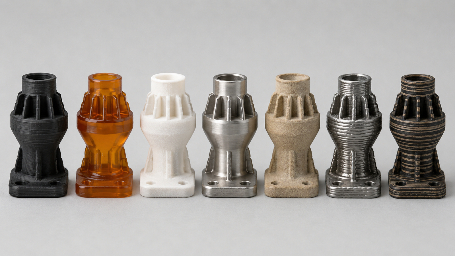
Seven processes at a glance
Swipe horizontally to compare all columns →
| Family | Also known as | Feedstock | Main materials | Supports | Best at | Watch out for |
|---|---|---|---|---|---|---|
| Material extrusion | FDM, FFF | Filament, pellets, pastes | Thermoplastics, TPU, bound metal/ceramic | Printed, removable | Low cost, big parts | Layer lines, anisotropy |
| Vat photopolymerization | SLA, DLP, LCD | Liquid resin / slurry | Rigid & elastomer resins, ceramics | Printed, removable | Fine detail, finish | Post-cure, resin aging |
| Powder bed fusion | SLS, MJF, LPBF/SLM, EB-PBF | Polymer or metal powder | Nylon, TPU; steels, Ti, Al, Ni, Cu | Polymer: none; metal: printed | Functional parts, dense metal | Cost, surface roughness |
| Binder jetting | BJ, sand printing | Powder + liquid binder | Metals, sand, ceramics | None (powder bed) | Speed, large ceramics | Green-part handling; thermal densification for metals and many ceramics |
| Material jetting | PolyJet, MJ | Photopolymer droplets | Rigid, clear, rubber-like resins | Printed, dissolvable | Accuracy, multi-material | Brittleness, cost |
| Directed energy deposition | DED, WAAM, LDED | Metal wire or powder | Weldable metals | Substrate & fixturing; separate supports uncommon | Huge parts, repair | Rough, needs machining |
| Sheet lamination | LOM, UAM | Sheets, foils, tapes | Paper, polymer, metal foil, ceramic tape | None | Cheap bulk, embedded sensors | Interlayer bonding and geometry limits |
Process-family classification follows ISO/ASTM 52900;1 the materials, support behavior, strengths, and limitations summarized above are synthesized from the family sections below and Refs. 2, 4, 7, 12, 19–23. The rest of this guide walks through each family — how it works, what it prints, and where it wins or struggles.
How does 3D printing work?
Every 3D printing process, from a desktop hobby machine to an industrial metal system, follows the same four-step logic.4 First, a digital model of the part is created in CAD software or captured by 3D scanning. Second, slicing software cuts that model into hundreds or thousands of thin horizontal layers and translates each one into machine instructions. Third, the printer builds the part layer by layer — extruding, curing, fusing, jetting, or laminating material, one cross-section at a time, each layer bonding to the one below. Fourth, the part goes through post-processing: support removal, cleaning, curing, sintering, heat treatment, or machining, depending on the process and the application. Designs are commonly exchanged as STEP, STL, or increasingly 3MF files, then repaired, oriented, supported, sliced, and converted into process-specific build instructions. Because most additive workflows avoid part-specific hard tooling, design iterations can often be implemented by revising and re-slicing the model — though orientation, supports, process parameters, validation, and post-processing may still need to change.3,4
Because the part is grown rather than cut, additive manufacturing can produce geometries that are difficult or uneconomical to make any other way — internal channels, lattices, consolidated assemblies, and organic topology-optimized shapes — and it does so without part-specific tooling, which is why it excels at prototypes, custom parts, and low-to-mid volumes.2,3 The idea is older than many assume: the first commercial systems date to the late 1980s, and the technology spent three decades maturing from rapid prototyping into genuine manufacturing.5
What are the seven types of 3D printing?
The international standard ISO/ASTM 52900 groups every 3D printing technology into seven process families, defined by how material is deposited and joined.1 Trade names multiply endlessly — FDM, SLA, DLP, SLS, SLM, DMLS, PolyJet, WAAM — but each one belongs to one of these seven families. Understanding the family tells you most of what you need to know about a technology's strengths, limits, and materials. Two things are worth keeping in mind as you read. First, the families are defined by the layer-forming mechanism, not the material — several families span polymers, metals, and ceramics through different feedstocks. Second, real machines increasingly hybridize: bound-metal filaments put metal in an extrusion machine, ceramic slurries put ceramics in a resin printer, and the furnace step after binder jetting or bound-material extrusion has more in common with powder metallurgy than with printing.1,7
1. Material extrusion (FDM / FFF)
How it works: material is selectively dispensed through a nozzle or orifice. In the best-known branch — fused deposition modeling (FDM/FFF) — a thermoplastic filament is melted and deposited as a fine bead that solidifies where it lands; other variants extrude pellets, pastes, highly filled metal or ceramic compounds, concrete, and direct-write inks. The filament approach was patented by Scott Crump in 1992.6 Materials: the widest and cheapest polymer palette in 3D printing — PLA, ABS, PETG, nylon, polycarbonate, flexible TPU, and high-performance polymers such as PEEK, plus bound-metal and bound-ceramic filaments that are debound and sintered after printing.7 Strengths: low cost, easy operation, large build volumes, tough real-world thermoplastics. Limitations: visible layer lines, the lowest fine-detail resolution of the polymer families, and anisotropy — parts are weakest across the layer bond.2 Typical uses: functional prototypes, jigs and fixtures, brackets, enclosures, and large low-cost parts.
2. Vat photopolymerization (SLA / DLP / LCD)
How it works: a vat of liquid photopolymer resin is selectively cured by light — a scanning UV laser in stereolithography (SLA), or a full-layer projected image in digital light processing (DLP). This is the original 3D printing process: Chuck Hull's 1986 stereolithography patent effectively founded the industry.8 Continuous variants can grow parts from the resin interface at high speed.9 Materials: rigid, tough, castable, high-temperature, and ceramic-filled resins — and, increasingly important, photopolymer elastomers that print flexible, rubber-like parts with elongations of several hundred percent.10 Vat photopolymerization — including DLP and continuous resin variants — is widely used for fine elastomer lattices such as footwear midsoles and compliant structures; ACS Material’s elastomer 3D printing service runs industrial DLP. Ceramic-loaded slurries printed by DLP, debound, and then sintered or otherwise densified yield dense technical ceramics, the precision route in our ceramic 3D printing service. Strengths: among the finest feature detail and smoothest as-printed surfaces available in mainstream polymer additive manufacturing. Limitations: resins are generally more brittle and less UV-stable than thermoplastics unless specifically formulated, parts need washing and post-curing, and build volumes are usually moderate.7 Typical uses: fine-detail prototypes, dental and hearing-aid parts, casting patterns, elastomer components, and technical ceramics via slurry routes.
3. Powder bed fusion: SLS, MJF, HSS, LPBF and EB-PBF
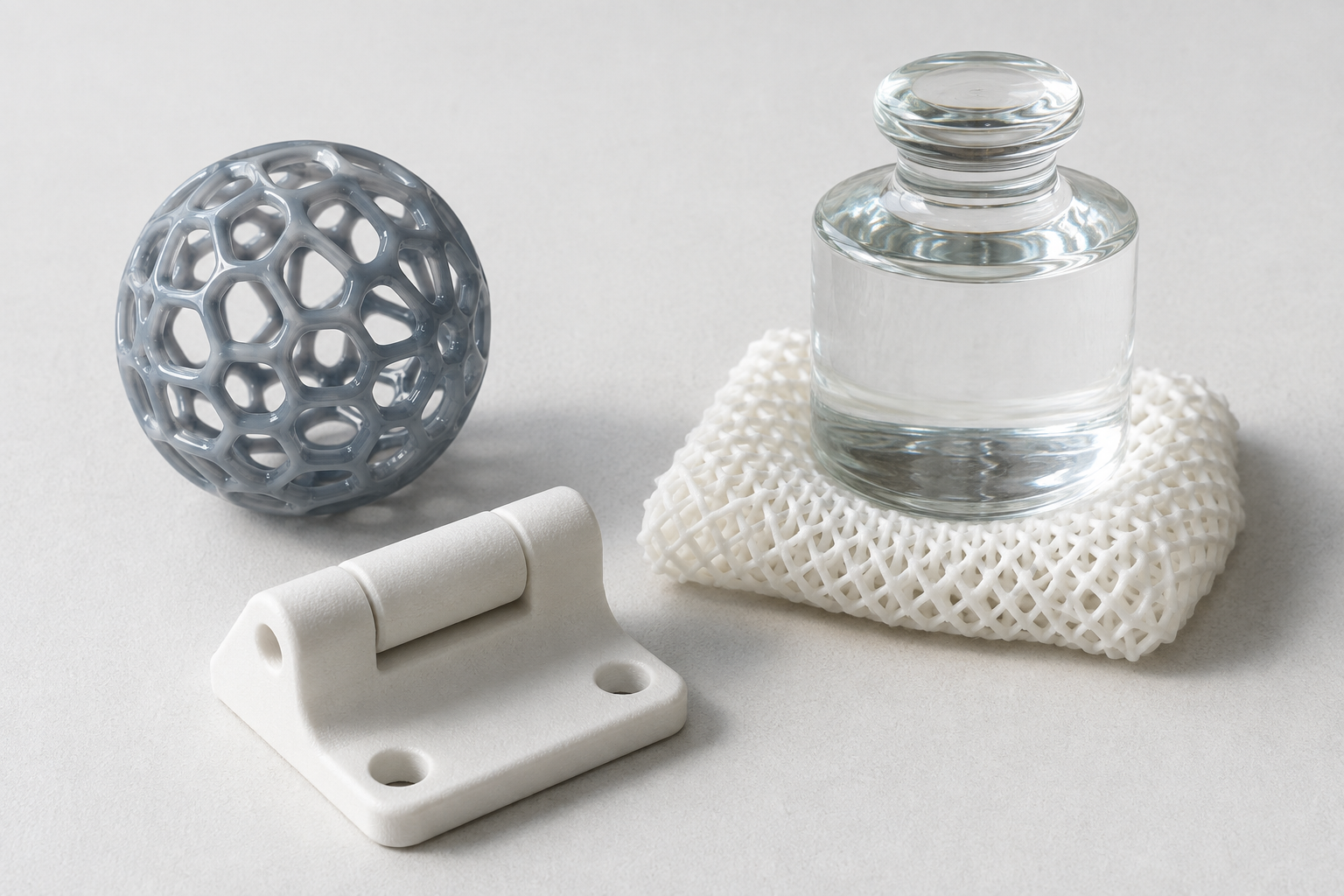
How it works: a thin layer of powder is spread across a build platform, and an energy source — usually a laser — selectively fuses the cross-section; the bed drops, fresh powder is spread, and the cycle repeats, with the unfused powder supporting the part as it grows. Carl Deckard's selective laser sintering (SLS) patent established the principle in 1989.11 The family splits into two branches. The polymer branch (SLS) fuses nylon (PA12, PA11) and TPU powders into tough, isotropic-leaning functional parts that normally require no separately printed supports, because the surrounding powder cradles the geometry during the build.12 Polymer powder-bed fusion also includes agent-assisted approaches such as Multi Jet Fusion (MJF) and High Speed Sintering, and metal PBF can use an electron beam as well as a laser — variants that share the powder-bed architecture but differ in energy delivery, materials, atmosphere, throughput, and surface character.1,4 The metal branch — laser powder bed fusion (LPBF), also marketed as SLM or DMLS — fully melts fine metal powder into dense (typically >99%) parts in stainless steel, titanium, aluminum, nickel superalloys, cobalt-chrome, and copper.13,14,15 Choosing among FDM, SLA, and SLS for a polymer part deserves a comparison of its own. Strengths: excellent mechanical properties, no supports (polymer), and for metals one of the strongest combinations of density, dimensional capability, and engineering-material availability in additive manufacturing.16,17 Limitations: machine and powder costs, rougher as-printed surfaces than resin processes, and for metals a demanding thermal process that requires engineering support. Typical uses: end-use nylon parts and, on the metal side, aerospace brackets, medical implants, conformally cooled tooling, and heat exchangers — the process behind our metal 3D printing service, which runs XDM laser powder bed fusion systems with build volumes up to 2000 × 2000 × 650 mm; see our guide to SLM vs DMLS vs binder jetting for how the metal processes compare.
4. Binder jetting
How it works: an inkjet-style printhead deposits liquid binder onto a powder bed, gluing each cross-section together at room temperature. For metals and many ceramics, the resulting “green” part is then debound and densified — by sintering, infiltration, or another material-specific route — while printed sand molds and cores are normally cured, depowdered, and finished for casting rather than densified. The technique was invented at MIT in the early 1990s and was the original process actually named “3D printing.”18 Materials: metals (sinter-based stainless steels and more),19 sand for casting molds and cores, and technical ceramics — where binder jetting is one of the few routes to genuinely large ceramic parts, including silicon carbide at meter scale.20 That large-format ceramic branch is the second route in our ceramic 3D printing service, with builds up to 1800 × 1000 × 700 mm. Strengths: fast, scalable, no thermal stress during printing (so no support structures), and uniquely suited to large parts and materials that cannot be melted. Limitations: the furnace step dominates the outcome — sintering routes shrink predictably and must be compensated in the green design, while final density and mechanical performance may trail fully melted equivalents, depending on the material system, porosity, and densification route.19,20 Typical uses: casting sand molds, sinter-based metal parts, and large technical-ceramic hardware. How a ceramic part moves from its printed state to a final densified component is a story of binder removal, densification route, and dimensional-change control.
5. Material jetting
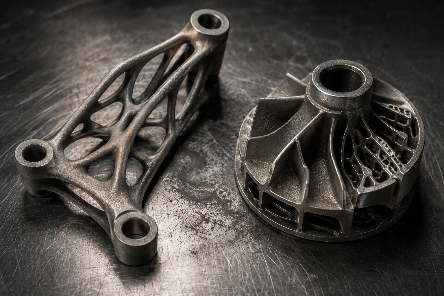
How it works: printheads jet thousands of droplets of liquid photopolymer that are UV-cured the instant they land — conceptually an inkjet printer working in 3D. Materials: rigid, clear, and rubber-like photopolymers, often several in one build, enabling multi-material and full-color parts with digitally blended properties.21 Strengths: outstanding dimensional accuracy and surface finish, plus one of the most mature voxel-level multi-material and full-color capabilities in additive manufacturing. Limitations: materials are comparatively brittle and age under UV, costs are high, and parts suit models better than hard service. Typical uses: realistic visual prototypes, anatomical models, and multi-material design studies.
6. Directed energy deposition (DED / WAAM)
How it works: metal powder or wire is fed directly into a melt pool created by a laser, electron beam, or electric arc, depositing weld-like beads that build up the part — on a fresh substrate or onto an existing component. Wire-arc additive manufacturing (WAAM) is the arc-and-wire variant favored for very large structures.22 Materials: weldable metals — steels, titanium, nickel alloys, aluminum. Strengths: the highest deposition rates in metal AM, very large build envelopes on gantry or robot systems — practical size set by machine reach, positioners, process stability, shielding, and downstream machining — and the unique ability to repair or add features to existing parts. Limitations: coarse resolution and rough surfaces — parts are near-net shape and are usually machined afterward.22 Typical uses: large aerospace and marine structures, turbine-blade repair, and cladding.
7. Sheet lamination
How it works: sheets of material — paper, polymer, metal foil, or ceramic-loaded tape — are bonded layer on layer (by adhesive, or ultrasonic welding for metals) and cut to shape each cycle. Materials: paper and polymer sheet, metal foils in ultrasonic additive manufacturing, and ceramic tapes in laminated object manufacturing (LOM).23 Strengths: low material cost, fast for bulky shapes, and the ability to embed sensors or electronics between layers. Limitations: limited geometric complexity, anisotropic bonding, and a niche industrial footprint compared with the other six families. Typical uses: visual models, tooling, embedded-electronics structures, and layered ceramic laminates.
What materials can be 3D printed?
In practice, the fastest way to narrow seven families to one or two candidates is to start from the material your part must be made of.2
| You need… | Leading process families | Where to go deeper |
|---|---|---|
| A rigid polymer part | Material extrusion (cheap, tough), vat photopolymerization (fine detail), polymer powder bed fusion / SLS (durable, support-free) | The three family sections above |
| A flexible / elastomer part | Elastomer DLP (vat photopolymerization), TPU by SLS or FDM, rubber-like material jetting | Elastomer 3D printing service10,26,27 |
| A metal part | Laser powder bed fusion (density + accuracy), binder jetting (sinter-based, economical), DED/WAAM (very large, repair) | Metal 3D printing service · 7 key metal alloys · large-format metal |
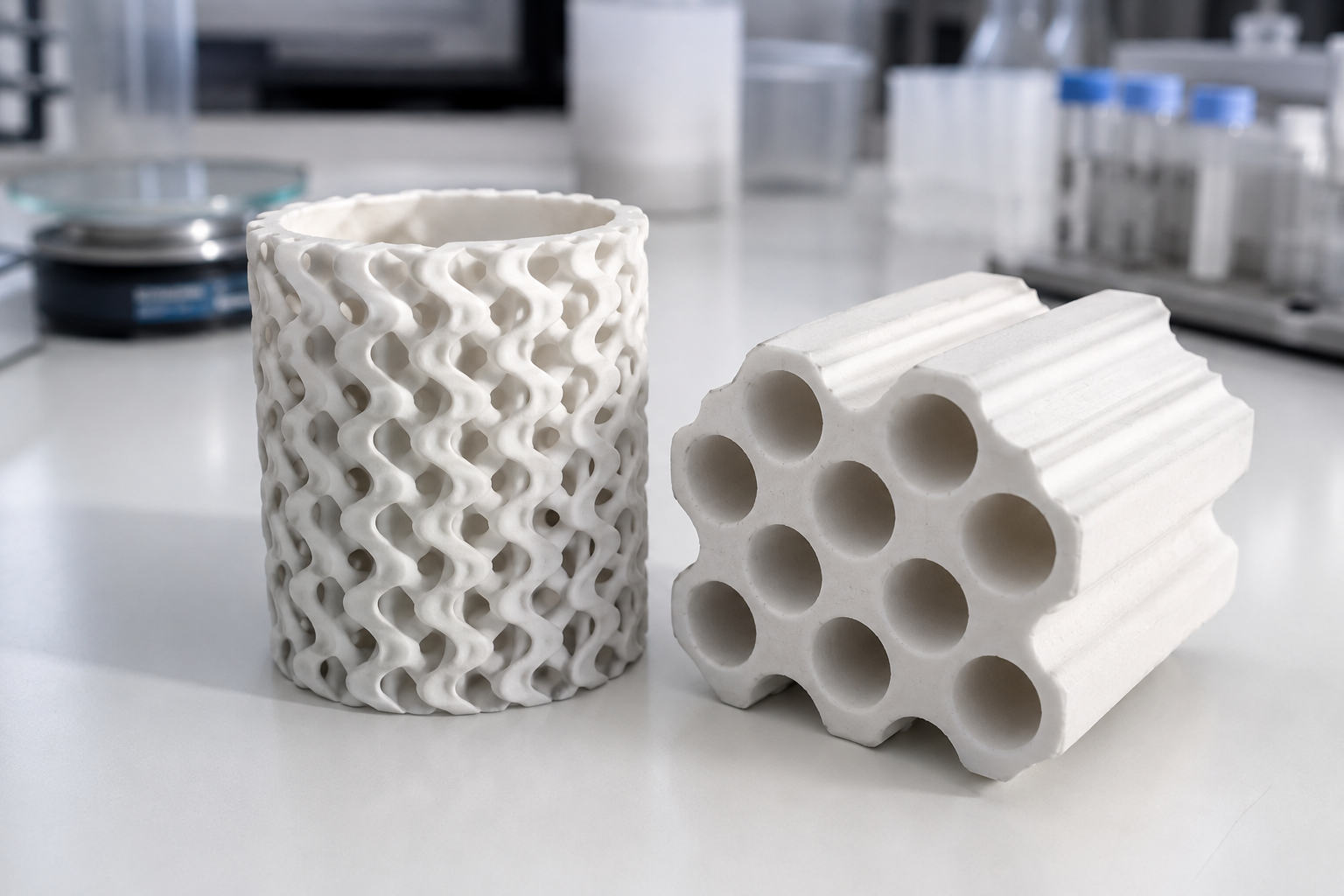
| A ceramic part | Ceramic DLP (fine, dense) and ceramic binder jetting (large format) — shaped green, then debound and densified | Ceramic 3D printing service20,24,25 |
Elastomers deserve a special note: additive manufacturing of rubber-like materials has advanced rapidly, driven by soft robotics, wearables, and lattice cushioning, with photopolymer elastomer systems now reaching elongations far beyond early resins.10,26,27 Ceramics, meanwhile, resist being simply melted like metals: most commercial technical-ceramic routes first shape a “green” body and then debind and densify it — which is why route selection and shrinkage control sit at the heart of sinter-based ceramic AM — while direct laser sintering, melting, and directed-energy routes do exist, they remain specialized because ceramics tolerate steep thermal gradients poorly.20,24 Bioceramics such as tricalcium phosphate and hydroxyapatite extend this branch into bone-scaffold research.25
How do you choose a 3D printing process?
Start with material compatibility, then eliminate the families that cannot accommodate the part’s size. Among the remaining routes, compare geometry and feature size, mechanical requirements, surface finish, quantity, post-processing, qualification needs, and total cost. More than one process is often technically feasible; the best choice is the one that satisfies the complete requirement set at acceptable risk and cost.2,3
- Low-cost thermoplastic prototype → material extrusion (FDM).
- Fine-detail polymer part → vat photopolymerization (SLA/DLP) or material jetting.
- Support-free functional nylon batch → SLS / MJF.
- Dense, precise metal part → laser powder bed fusion.
- Very large near-net metal, or repair → DED / WAAM.
- Fine ceramic → ceramic DLP; large ceramic → binder jetting; specialized routes assessed per project.
The interactive selector below applies the same logic — answer three questions and it suggests the family that typically fits, plus a runner-up. It mirrors the comparisons in this article; treat it as orientation, not a substitute for engineering review.
What are the advantages and limitations of 3D printing?
Advantages. No part-specific tooling, so first parts and design changes are fast and cheap; geometric freedom that machining and molding cannot match — internal channels, lattices, consolidated assemblies; economical low-to-mid volumes and one-off customization; and, for subtractive comparisons, far less material cut away as waste.2,3
Limitations. At high volumes, molding and machining usually win on unit cost; most processes leave some anisotropy or process-specific defects; post-processing is a real cost, not an afterthought; build size and throughput are bounded per process; and qualification — proving a printed part repeatably meets spec — takes engineering effort. “Printable” is not the same as “suited to printing.”2,3
When is 3D printing the wrong choice?
An honest guide should say so: skip additive manufacturing when the geometry is simple and annual volumes are high enough for molding or stamping to amortize; when a standard catalog part already exists; when an injection mold is already paid for; when tolerances and surfaces are only achievable economically by volume machining or grinding; when no qualified material-process combination exists for the duty; or when post-processing cost would exceed the benefit of printing the shape. 3D printing earns its place through geometry, speed, or customization — not by default.3
How much does 3D printing cost?
There is no single rate card — cost is driven by material (polymer resins to metal powders differ by orders of magnitude), part volume and height (machine time depends on process-specific factors such as layer count, toolpath length or scanned area, exposure and recoating time, and deposition rate), how fully the build is packed, support volume, post-processing and inspection effort, quantity, and any qualification requirements. That is why serious providers quote per project from the actual geometry: the same design can be economical in one process and unreasonable in another.2,3
How accurate is 3D printing?
“Precision” in 3D printing bundles several different ideas — resolution, accuracy, repeatability, and tolerance — and they are not interchangeable. A process's layer thickness or pixel pitch is a resolution figure, not a promise about the dimensional tolerance of a finished part; what a part actually holds depends on geometry, material, thermal history, and post-processing, and standardized test artifacts exist precisely because those factors interact.28 As broad orientation: vat-photopolymerization and material-jetting processes can resolve some of the finest polymer features; laser powder bed fusion holds the tightest metal tolerances, with critical faces machined afterward; sinter-based routes add predictable shrinkage that is compensated in the green design.13,16 Repeatability — whether part fifty measures the same as part one — is a separate question again, governed by machine calibration, powder or resin condition, and thermal management rather than by the headline resolution number.28 We take this subject apart properly — definitions, realistic tolerance ranges by process, and the trade-offs — in our guide to how to define precision in 3D printing.
What post-processing do 3D printed parts need?
Almost every printed part leaves the machine unfinished — post-processing is part of the process, not an optional extra.4
| Process | Typical post-processing |
|---|---|
| FDM / material extrusion | Support removal, sanding, optional annealing |
| SLA / DLP | Washing, post-cure, support removal |
| SLS / MJF | Depowdering, bead blasting, optional dyeing |
| Metal LPBF | Depowdering, stress relief, support removal, machining of critical faces, and HIP when required |
| Binder jetting | Curing, depowdering; debinding + sintering or infiltration (metals/ceramics) |
| Indirect ceramic routes (DLP, BJ, DIW) | Debinding, densification, grinding/lapping of critical faces |
| DED / WAAM | Heat treatment and machining to final geometry |
Typical steps per family, synthesized from Refs. 4, 7, 12–16, 19, 20, 24.
What is 3D printing used for?
Aerospace & defense lean on topology-optimized brackets, fuel-system hardware, and large single-piece structures where buy-to-fly ratios and part consolidation pay off.2,13 Medical & dental teams print patient-specific titanium and cobalt-chrome implants, surgical guides, dental frameworks, and bioceramic scaffolds for bone-regeneration research.14,25 Medical use always depends on the specific material, process validation, traceability, sterilization route, and applicable regulatory requirements. Energy and thermal management exploit internal channels that can be difficult or impossible to machine conventionally — heat exchangers, cooling structures, and catalyst supports. Automotive and industrial tooling use conformally cooled mold inserts, custom jigs, and low-volume production parts. Robotics and consumer products increasingly combine rigid and elastomer prints — soft grippers, tactile-skin support lattices, lattice midsoles, and wearables.26,27 Research across materials science runs on printed fixtures, membranes, scaffolds, and one-off experimental hardware in every material class this article covers.3 Beyond these, construction printing extrudes concrete at building scale, the food and pharmaceutical industries print dosage forms and confections, and educators use desktop extrusion machines as the on-ramp for the whole field — the same four-step logic at every scale.2
3D printing at ACS Material
ACS Material operates project-based 3D printing services across three material classes. Our metal 3D printing service runs XDM laser powder bed fusion systems with build volumes up to 2000 × 2000 × 650 mm — large-format capability that is less commonly available at service scale — in stainless steel, titanium, aluminum, nickel, cobalt-chrome, and copper alloys. Our elastomer 3D printing service prints flexible photopolymer parts (Shore 60A–80A) on industrial DLP systems up to 768 × 432 × 450 mm — lattice midsoles, compliant robotic structures, seals, and grips. Our ceramic 3D printing service pairs precision ceramic DLP with large-format ceramic binder jetting up to 1800 × 1000 × 700 mm in alumina, zirconia, silicon nitride, silicon carbide, and bioceramics. For teams bringing metal AM in-house, we also supply the XDM 3D metal printers themselves. What ties the three services together is materials: as an advanced-materials supplier, ACS Material approaches additive manufacturing from the powder, resin, and slurry side as much as from the machine side; materials are one of the main determinants of part performance, alongside design, process control, post-processing, and inspection. Every project is engineered and quoted individually — send us your design (STEP/STL) and requirements to get started.
FAQ
1. What is 3D printing in simple terms?
3D printing, or additive manufacturing, is a way of making physical objects directly from a digital model by adding material layer by layer — instead of cutting it away from a solid block (machining) or squeezing it into a mold (casting or injection molding).1
2. How does a 3D printer work?
Software slices a 3D model into thin layers; the printer then forms those layers one at a time — by extruding melted plastic, curing liquid resin with light, fusing powder with a laser, jetting droplets or binder, depositing molten metal, or bonding sheets — and each layer bonds to the previous one until the part is complete. Most parts then get post-processing such as support removal, curing, sintering, or machining.4
3. Which 3D printing process makes the strongest parts?
For many load-bearing engineering applications, metal additive manufacturing offers the broadest structural-performance range — laser powder bed fusion parts can approach wrought properties depending on alloy, orientation, and post-processing such as HIP and heat treatment.16,17 Among common polymer routes, SLS nylon and fiber-reinforced material extrusion are often durable choices, but the best process depends on load direction, temperature, fatigue, environment, geometry, and qualification requirements.7,12
4. What is the cheapest way to 3D print something?
For most parts, material extrusion (FDM) is the least expensive route — machines and thermoplastics are inexpensive and the process scales from desktop to large formats. Costs rise through resin and powder polymer processes and are highest for metal AM, where powder, machines, and post-processing dominate.2,3
5. What is the difference between metal and plastic 3D printing?
Metal additive manufacturing is usually more expensive because feedstocks, equipment, atmosphere control, safety systems, inspection, and post-processing are demanding. Melt-based routes such as LPBF commonly require engineered supports, inert gas, stress relief, and machining, while sinter-based routes such as binder jetting add debinding and densification cycles — so the cost structure depends strongly on the process.13,14 Polymer processes are cheaper and faster to iterate, and cover a huge property range from rigid to rubber-like, but plastics cannot replace metals where temperature or load demands them.
6. How accurate is 3D printing?
It depends on the process, geometry, material, and post-processing — resolution figures such as layer thickness or pixel pitch are not the same thing as dimensional tolerance. Fine-feature processes (vat photopolymerization, material jetting) resolve the smallest details; metal LPBF parts commonly have critical faces machined to final tolerance; sinter-based routes shrink predictably and are compensated in the design.28 Our precision guide covers realistic expectations by process.
References
This article is provided by ACS Material LLC for educational purposes. Process characteristics, material properties, and accuracy figures discussed here are typical of each process family in general; the capabilities achievable for any specific part depend on geometry, material, machine, and post-processing, and are confirmed per project at quotation. The interactive selector is a schematic teaching tool reflecting the qualitative comparisons in this article, not predictive software or a substitute for engineering review. Sample images are representative.