
Lattice structures are how 3D printing turns one material into many: the same polymer, printed as an open network of struts or surfaces, can be soft as foam or stiff beyond its weight class — governed by a scaling law engineers have used for decades.1 This guide explains the lattice types that matter (strut, TPMS, honeycomb), the Gibson–Ashby relationship that predicts their stiffness, which printing processes build them well, and how lattice design shows up in real parts — from zoned shoe midsoles to compliant robotics.
Why lattices at all
Nature settled this argument long ago: bone, wood, and cork are all cellular solids — stiff where load flows, hollow where it does not — and the engineering theory of such materials was systematized in Gibson and Ashby’s classic treatment of cellular solids.2 What 3D printing added is control: instead of the random cells of a foam, a printer places every strut and wall deliberately. The results reset intuitions about what light structures can do — hollow-tube metallic microlattices at less than a hundredth the density of water that recover from 50% compression, and octet-based metamaterials whose stiffness-to-weight barely degrades across three orders of magnitude in density.3,4 Between those research extremes sits the practical payoff: one material, one build, and a part whose local stiffness, weight, cushioning, and flow behavior are all design variables. Ashby’s framing captures why this matters: turning a solid into a cellular architecture extends its single-valued properties into ranges — one polymer becomes a family of effective materials, selected by geometry instead of by chemistry.1
The lattice types that matter
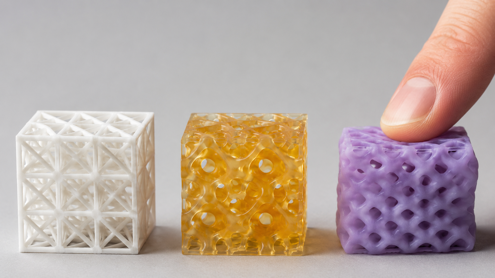
Strut-based lattices are frameworks of beams meeting at nodes — cubic, BCC, octet, and their many relatives — the workhorse family in metal printing, where unit-cell choice sets whether the structure carries load by stretching its members or bending them.5 TPMS lattices (triply periodic minimal surfaces: gyroid, diamond, primitive) replace beams with smooth, continuous surfaces — in their sheet-based form dividing space into interpenetrating channel networks — no sharp nodes, naturally self-supporting in many orientations, and excellent at spreading stress, which is why the gyroid became the poster child of printed lattices.6 Honeycombs are the 2D veterans: prismatic cells, extremely efficient in one loading plane, anisotropic by construction.2 And stochastic (foam-like) lattices deliberately reintroduce randomness when isotropy and energy absorption matter more than peak stiffness. The families are not interchangeable: topology strongly influences the dominant deformation mechanism, and that mechanism largely shapes the scaling behavior. Two independent dials deserve separating in your head: relative density (how much material fills the volume) sets the property level, while cell size at fixed density sets feature scale — finer cells mean thinner struts, smoother pressure distribution, and harder printing. And the dials need not be constant: graded lattices vary density or cell type across the part, which is precisely the trick behind zoned cushioning.5,6
The Gibson–Ashby law: the one equation worth knowing
For a lattice made of a solid with modulus Es, the effective modulus scales with relative density (the fraction of space that is actually material) as a power law: E*/Es ≈ C(ρ*/ρs)n.1,2 The fitted exponent reflects the topology and its dominant deformation mode — and it can also vary with relative-density range, loading direction, material behavior, defects, and manufacturing process. Bending-dominated architectures — foams and low-connectivity lattices whose members flex under load — follow n ≈ 2 in stiffness, with strength scaling near the 1.5 power. Stretch-dominated architectures — highly connected topologies like the octet truss whose members carry load axially — approach the far more efficient n ≈ 1.1,4
The practical consequence is dramatic. At 10% relative density, an ideal stretch-dominated lattice retains on the order of a tenth of its parent material’s stiffness — while a bending-dominated one retains around a hundredth. Same material, same weight, an order of magnitude apart. That is why topology selection comes before density selection, and why lattice reviews of printed structures spend so much effort testing where real printed lattices sit relative to the ideal Gibson–Ashby exponents — process-induced defects at struts and nodes generally push printed hardware away from the textbook line, which is a manufacturing-quality conversation as much as a design one.5 Stiffness is not the whole story either: in compression, cellular structures typically show a long stress plateau before densification — the mechanism behind their excellent energy absorption — and bending-dominated architectures, “weaker” on the stiffness chart, are often exactly what impact and cushioning applications want.1,2
Explore the scaling law
Pick a topology class and a relative density; the explorer shows the predicted stiffness fraction and where it lands on the log-log scaling curves. Idealized textbook behavior, for intuition — printed lattices carry process effects the model does not see.
How lattices actually get printed
Every additive family in the ISO/ASTM taxonomy can print some lattice; a few print them superbly.7,8 Vat photopolymerization is well suited to fine, smooth lattice features: DLP resolves thin struts and smooth TPMS walls, continuous-interface variants improve throughput for suitable geometries, and paired with elastomer resins they created the modern cushioning lattice — the midsole story below.9,10 Polymer powder bed fusion (SLS/MJF) prints tough nylon and TPU lattices normally without separately printed support structures — the surrounding powder supports the build — provided every cell connects to a powder-escape path.11 Metal LPBF builds structural lattices for lightweighting, heat exchange, and medical scaffolds, with melt-pool physics setting the floor on strut size and surface quality.12 FDM prints coarse lattices honestly and cheaply — think infill-scale cells rather than midsole-scale ones — and for fine cells it hands over to the routes above. Orientation matters everywhere: many lattice topologies are largely self-supporting at sensible angles, which is part of their manufacturing charm, but overhung struts near horizontal still sag or roughen in resin and metal alike. If you are still choosing among the polymer processes themselves, start from our FDM vs SLA vs SLS comparison; for the full seven-family map, the 3D printing overview guide has it.
Midsoles and cushioning: lattices as tuned foam
The shoe midsole is the lattice application everyone has touched. A conventional homogeneous foam midsole starts from a comparatively limited material-density palette; a printed elastomer lattice grades topology, cell size, strut thickness, and relative density continuously across a single part — softer under the heel strike, supportive under the arch, resilient at toe-off — one resin, one build, no assembly.9,13 The same logic generalizes to every cushioning problem: seat pads, helmet liners under research, grips, protective inserts — anywhere a molded foam is really a compromise between zones that wanted different stiffness. The elastomer’s own character still matters underneath the architecture — rebound versus damping, tear strength at thin struts, compression set under sustained load — which is why lattice design and material selection are one conversation, not two. The material side of this story — why photopolymer elastomers are particularly well suited to fine, smooth lattice structures, and what Shore hardness does and does not tell you — is covered in our flexible materials guide; the two articles are designed to be read together.
Soft robotics and compliant mechanisms
Soft robotics runs on structures that deform on purpose, and printed lattices are one of its native building blocks: graded-stiffness skins, energy-absorbing feet, compliant joints that replace pinned hinges with designed flexure.13,14 Lattices earn their place here for a subtler reason than lightness — they make anisotropy a feature. A cell stretched in one axis flexes easily that way and resists the other, so a single printed component can be soft to grasp with and stiff to push with. That directional tuning, difficult or uneconomical to mold as a single integrated part, is exactly the kind of behavior elastomer DLP can deliver when unit-cell geometry, orientation, supports, drainage, exposure, and post-cure are engineered together. The research frontier goes further still — auxetic cells with negative Poisson’s ratio that fatten when stretched, programmable buckling, multistable cells — but the workhorse value today is simpler: designed compliance, repeatable in production.13
Design rules that keep lattice parts printable
Lattice design fails at the details, so the checklist is short and non-negotiable.15 Escape paths: every internal volume needs openings — uncured resin and unfused powder must leave, and powder-route quality itself depends on clean removal.16 Node design: struts meeting at sharp angles concentrate stress and collect print defects; fillet the nodes. Minimum feature honesty: struts and walls below the process’s real minimum print as suggestions, not structure — and in elastomers, thin members tear at demolding before they ever see service. Skins and transitions: lattice-to-solid boundaries are stress risers; grade the transition over a few cells. Verification: lattice stiffness is a structural property — measure it on representative printed coupons, not from the CAD relative density, because geometric capability differs by process and orientation.17 One more sizing rule of thumb saves prototypes: keep several unit cells across any load-bearing thickness — with only one or two cells through the section, the part behaves like a frame of individual beams, not like the continuum “material” the scaling law describes — and final geometry still earns its numbers through convergence checks, simulation, and printed-coupon testing.2 Our elastomer 3D printing service applies these principles during project review and process planning on industrial DLP builds up to 768 × 432 × 450 mm; for rigid strut lattices in nylon or metal, treat this section as process-agnostic engineering education.
FAQ
1. What is a lattice structure in 3D printing?
A deliberately designed open cellular architecture — repeating struts, surfaces, or cells — that replaces solid material with engineered structure, trading density for tuned stiffness, weight, cushioning, or flow behavior.1,2
2. Why is the gyroid so popular?
It is a TPMS: smooth continuous surfaces, no sharp strut-junction nodes, self-supporting in many print orientations, and near-balanced behavior across directions — and a sheet-based gyroid separates space into two interpenetrating, non-intersecting channel networks for flow. A rare combination of printability and mechanics.6
3. Which lattice is strongest?
In ideal scaling analyses, at comparable relative density and manufacturing quality, stretch-dominated topologies like the octet truss lead in stiffness and strength — that is the n ≈ 1 advantage. Real printed performance shifts with defects, node geometry, orientation, minimum feature size, surface condition, material behavior, and loading mode. But “strongest” is the wrong question for cushioning, energy absorption, or fatigue, where bending-dominated and TPMS architectures often serve better. Match the deformation mechanism to the job.1,4,5
4. Can lattices be simulated instead of tested?
Simulation guides design well, but printed lattices carry strut-thickness variation, surface roughness, and node defects the ideal model omits — published testing consistently finds real exponents and strengths offset from textbook values. Simulate to iterate, then verify on printed coupons using standard mechanical test methods.5,18
5. What is the best process for elastomer lattices?
Industrial DLP with photopolymer elastomers for fine cells, smooth skins, and zone grading; TPU by SLS for rugged batch parts — normally without separately printed supports — at coarser cells. FDM TPU covers budget prototypes. The flexible-materials guide linked above walks the trade-offs.9,10,11
References
This article is provided by ACS Material LLC for educational purposes. The Gibson–Ashby relationships discussed and visualized are idealized textbook scaling laws; printed lattices exhibit process-dependent deviations, and structural use requires testing of representative printed specimens rather than reliance on model predictions. ACS Material operates an elastomer DLP printing service; coverage of metal, nylon, and other lattice routes here is educational. The interactive explorer is a schematic teaching tool. Sample images are representative.