Ceramic 3D printing earns its keep in a specific territory: parts too geometrically complex to machine from a blank, too low-volume to justify pressing tooling, and demanding enough — in heat, wear, chemistry, electrical insulation, or biocompatibility — that ceramic-specific performance outweighs the advantages of polymers and metals.1 This guide maps that territory application by application, then lays down the design rules that keep a ceramic part printable and compatible with its selected consolidation path — because in ceramics, design for manufacturing is not a polish step; it is the difference between a part and a crack.
Where ceramic AM wins: the three-condition test
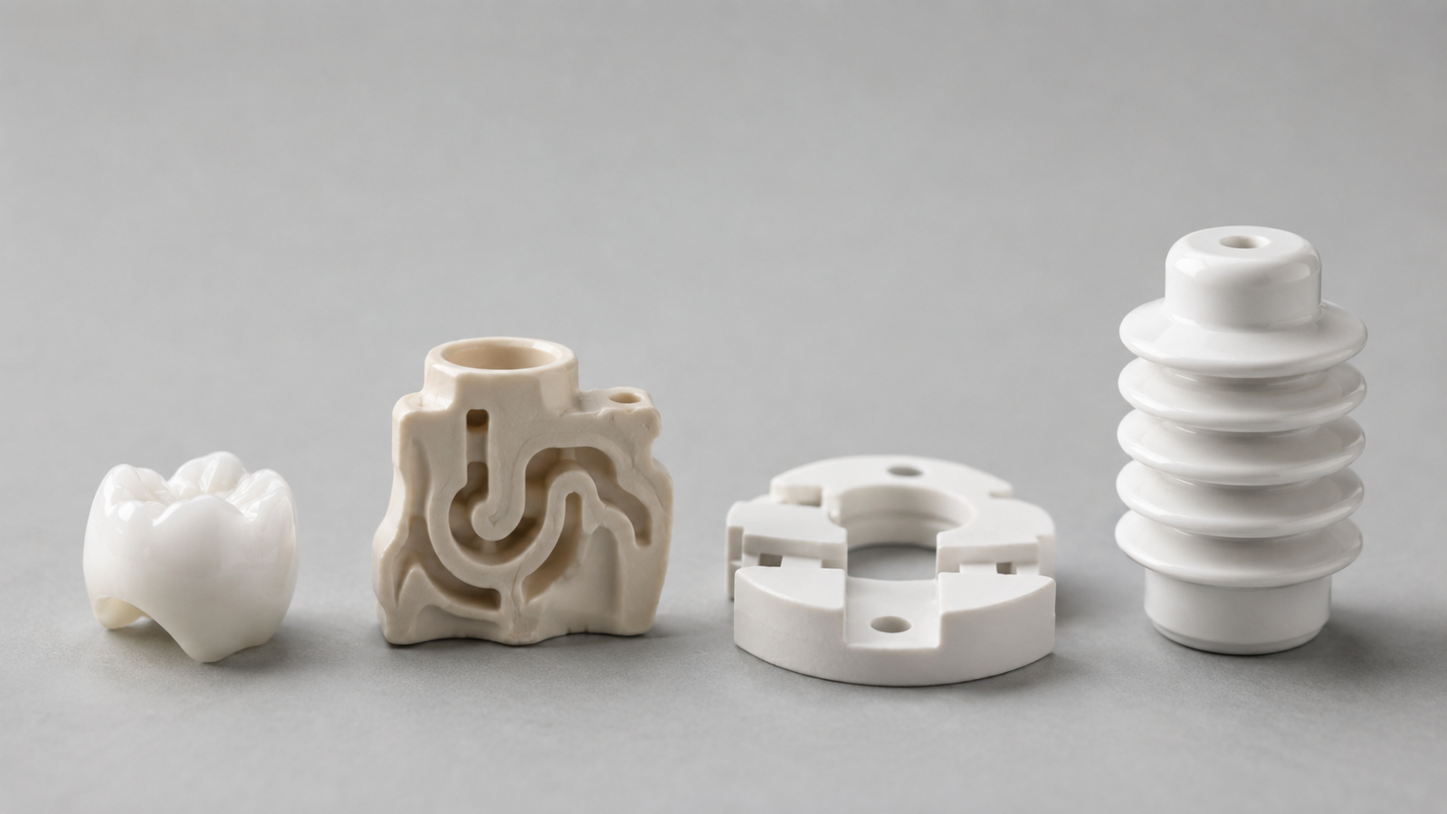
Run any candidate part through three questions. Does the geometry defeat subtraction? Internal channels, conformal passages, lattices, and undercuts are brutal to machine in fired ceramic — one of the hardest material classes to cut — while printing can avoid the machining and assembly entirely, provided those features stay printable, drainable, cleanable, and inspectable.1,2 Are volume and tooling economics favorable? Pressing and injection molding amortize dies over long runs; printing amortizes no tooling, so it is often strongest at low-to-moderate volumes where geometry, customization, or avoided tooling outweigh printing, firing, finishing, inspection, and yield costs — there is no universal part-count crossover. Does the duty require ceramic at all? If a polymer or metal survives the heat, wear, or chemistry, it is usually cheaper — ceramic AM is for when the material is non-negotiable. Score three yeses and printing is often the strongest candidate; score one and it is a conversation. The applications below are simply the places where industry keeps scoring three. A fourth, quieter condition threads through them all: lead time. Tooling iterations are typically measured in weeks to months; a printed ceramic revision is often measured in print-and-fire cycles — and in development programs, that clock difference is frequently the deciding budget line.
Dental & medical: zirconia’s home game
Dentistry is one of the most active and comparatively mature printed-ceramic application areas: crowns, copings, and bridge frameworks in yttria-stabilized zirconia are one-off geometries by definition (every mouth is a custom job), demand toughness and aesthetics no other white material matches, and slot naturally into the digital scan-design-manufacture workflow — which is why additive zirconia has advanced fastest under dental pull.3,4 Beyond the visible teeth, the research frontier includes bioceramic scaffolds — calcium-phosphate chemistries printed as bone-mimicking porous structures — where the pore architecture itself is the therapeutic feature and printing is the only way to specify it.5 The honest boundary belongs in every sentence of this section: clinical use runs through regulatory qualification of the specific material, workflow, and device — the physics travels; the approvals do not.3,4 Adjacent to the clinic, the same package serves ceramic-appropriate duties: custom bioceramic research scaffolds beyond the calcium phosphates, wear-facing instrument components, and device-development programs where the biocompatibility and regulatory pathway are being established deliberately.
Investment-casting cores & aerospace
Some of the highest-value printed ceramics are never seen in the final product: investment-casting cores — the sacrificial ceramic inserts that form internal cooling passages inside cast turbine blades and complex metal parts. Printing attacks the pain directly: core geometries are exactly the serpentine, thin-walled internal shapes that tooling struggles with, quantities are development-scale, and iteration speed is worth real money in engine programs — ceramic stereolithography demonstrated integrated mold-and-core builds early, and cores remain a flagship use of the vat route.2,1 The same logic extends to aerospace-adjacent hardware — insulators, nozzles, sensor housings, and selected components where oxidation resistance, electrical insulation, low density, or temperature capability favor ceramics over the incumbent metal or composite.6 Core work also showcases a distinctly ceramic virtue: the part is designed to be destroyed — leached or broken out after casting — so its specification is about controlled strength and chemistry as much as geometry, a requirement space injection tooling was never built to iterate.
Semiconductor, plasma & laboratory hardware
Fabs and labs quietly consume precision ceramics: wafer-handling fixtures, plasma-facing rings and nozzles, high-purity alumina labware, insulating standoffs, and custom jigs that must shrug off heat, vacuum, plasma chemistry, and contamination rules simultaneously.1 This is natural printing territory because the parts are custom by nature (every tool and experiment differs), quantities are small, high-purity alumina prints to near-full density with properties comparable to conventionally formed material, and lead time — not unit price — is usually the pain being purchased away.7,8 For researchers, the same route turns a sketch of a custom crucible, ferrule, or reactor insert into fired hardware without a tooling line item. Purity discipline earns a note here: semiconductor and analytical duties often specify high-purity alumina grades precisely because contamination budgets are measured in parts per million — another selection axis the materials guide walks in depth.
Electrical insulation & thermal management
The quietest workhorse category: insulators. Ceramics’ electrical resistance plus temperature capability owns high-voltage standoffs, feedthroughs, connector bodies, and heater isolation — alumina by default, with printing entering wherever the insulator’s shape is custom or internally featured.1 On the thermal side the casting flips: silicon nitride carries mechanical load through brutal temperature swings (its thermal-shock resistance is the family signature), while the silicon carbide family moves heat — and its additive story is route-specific: polymer-derived processes have demonstrated printed silicon-oxycarbide (SiOC) lattice structures,9,10 while dense and reaction-bonded SiC components rely on route-specific approaches such as printed porous preforms followed by reactive silicon infiltration, with material identity specified per route.11 Material selection across these duties is its own discipline; our technical ceramics comparison walks the four families axis by axis.
The six design rules of printable ceramic
The rules below span shaping, green-part handling, and final consolidation — the chain our how ceramic 3D printing works pillar walks path by path. Debinding-specific rules apply to binder-based routes; shrinkage, support, and distortion rules must be interpreted for the selected consolidation path. Read them as a system rather than as universal numerical limits — ceramics forgive geometry sins less than any other AM family, because the furnace re-litigates every design decision.12,6
- For binder-based routes, keep walls uniform — and respect the thickness ceiling. Debinding gas escapes by diffusion, so thick solid sections stretch schedules from hours toward days and eventually crack; uniform, moderate walls debind predictably. When a section must be massive, core it out.12
- Radius every internal corner. Ceramics concentrate stress and do not yield; sharp inner corners are pre-written crack reports — in the green state, in the furnace, and in service.6
- Design for shrink-aware tolerancing — per route. Binder-based parts densified by sintering can undergo substantial linear shrinkage, with the actual value material-, direction-, loading-, and furnace-cycle-dependent; calibrated scaling factors handle the bulk, and tight fits get post-fire grinding stock or as-fired tolerance bands. Infiltrated, reaction-bonded, and directly consolidated routes follow different dimensional-change models.12,13
- Give hollow volumes a drain. Slurry routes must evacuate uncured material from internal channels, and powder routes must depowder them: every enclosed volume needs an escape hole sized for its route.2,14
- Plan green handling and orientation. Green parts are chalk-fragile; unsupported spans, delicate free ends, and heavy overhangs need orientation strategy and, in vat routes, support placement chosen where removal scars are acceptable.2
- Buy confidence with representative coupons. Use project-specific witness coupons fired alongside the build to verify material response, shrinkage, orientation, and firing behavior. Separately, standardized geometric artefacts such as those in ISO/ASTM 52902 support AM-system capability assessment and calibration — a system-level exercise, not a per-furnace-run requirement.13
Try it: the design feasibility triage
The tool below runs a first-pass DFM triage: pick a geometric feature and a process route, and it returns a verdict — often feasible, proceed with caution, or redesign / validate — with the rule behind it. It is a teaching companion to the six rules, not a substitute for engineering review.
When NOT to print ceramic — the honest section
Three exits save budgets. Volume: at sustained production quantities of identical parts, pressing, injection molding, and extrusion usually win on unit cost — AM’s tooling-free economics cut both ways, and the crossover point is project-specific rather than universal.15 Simple geometry: a plain bushing, plate, or rod is cheaper machined from fired blanks or formed conventionally; printing buys complexity you are not using. Toughness-critical duty: if the failure mode is impact or gross flexure, even zirconia has ceilings a metal ignores — sometimes the right ceramic part is a metal part, and the seven-family map in our 3D printing overview guide is the honest place to restart.16,17 When a part passes the three-condition test and the six rules, our ceramic 3D printing service takes it from STL through debind, sinter, and dimensional verification — and flags the rule violations before the furnace does.
FAQ
1. What is ceramic 3D printing used for?
The recurring wins: dental zirconia restorations, investment-casting cores with internal passages, semiconductor and lab fixtures, custom electrical insulators, thermal hardware, and bioceramic research scaffolds — all sharing complex geometry, low volume, and duties only ceramics survive.1,3
2. What is the minimum wall thickness for ceramic 3D printing?
Route- and material-specific — slurry DLP resolves finer walls than powder routes — but the binding constraint is often the maximum: thick solid sections are debinding liabilities. Design to your provider’s published window for the specific material, and treat both limits as real.12,2
3. Can 3D printed ceramics be used in the human body?
The materials science says yes for qualified chemistries — zirconia and bioceramics carry long clinical pedigrees — but any actual clinical use runs through regulatory qualification of the specific formulation, process, and device. Educational content is not a clearance.3,4,5
4. Why do printed ceramic parts crack?
Crack origin is route-dependent. In binder-based routes, cracks commonly emerge during drying, debinding, or sintering — too-fast binder escape, too-thick sections, uneven shrinkage. In direct thermal processes, steep gradients can initiate cracking during printing itself. On every route, sharp internal corners, unsupported spans, and non-uniform mass make the part less forgiving; the six rules above are the prevention checklist.12,6
5. Is ceramic 3D printing expensive?
Per part, usually more than machining a simple shape and less than tooling up for a complex one — the economics hinge on geometry and quantity. Complexity carries little printing premium while volume does: at prototype and low-to-moderate quantities with internal features, printing is often the strongest candidate; at sustained commodity volume it usually is not — and the crossover is project-specific.15,1 Quoting tip: send the actual duty (temperature, load, chemistry, tolerance) along with the STL — material and route selection move price more than geometry does.
References
This article is provided by ACS Material LLC for educational purposes. Application characterizations and design rules are general patterns from the cited literature and industrial practice; actual feasibility windows (wall thicknesses, feature sizes, drain-hole diameters, tolerances) are route-, material-, and provider-specific. Medical and dental content is educational only — clinical use requires regulatory qualification of the specific material, process, and device. The design triage tool is a qualitative teaching aid, not an engineering review. ACS Material operates a slurry-DLP ceramic printing service; coverage of other routes is educational. Sample images are representative.