Most commercial ceramic 3D printing routes first shape a particle-based feedstock or porous preform — but the path from printed shape to final component is not universal.1 Some parts are debound and sintered to density, some preforms are infiltrated or reaction-bonded, and a smaller group of direct thermal processes consolidates ceramic during printing itself. This guide walks the most common journey in commercial practice — binder-based shaping, debinding, sintering — names the other two consolidation paths so you can tell them apart, and unpacks the dimensional change that binder-based, sintering-densified designs must plan for.
The green-part idea: why ceramics print differently
Polymers melt and metals weld their way through most 3D printing, but ceramics resist that logic: melting points are extreme, thermal-shock brittleness punishes steep gradients, and so most commercially practical ceramic AM routes avoid fully melting the final ceramic during shaping. So most commercially common binder-based ceramic AM routes print a particle–binder composite instead: ceramic particles carried in an organic binder that the printer can shape at room temperature.2 The resulting green part is geometrically complete but mechanically humble — think pressed chalk — and it contains a significant volume of binder that must leave before the ceramic can densify. In the ISO/ASTM process taxonomy these routes span several families (vat photopolymerization, binder jetting, material extrusion, and more), and for the binder-based routes that dominate commercial practice, the ceramic-specific truth is that printing is step one of three, ahead of debinding and sintering.3 The composition of that composite is a real design variable: slurry routes commonly carry very high ceramic solids loadings so the green body starts dense and shrinks predictably, while powder-bed routes start from loosely packed dry powder and make up ground later. Everything downstream — achievable wall thickness, firing behavior, final density — is negotiated at this feedstock stage. The additive field learned this discipline early — ceramics rode along from the first wave of AM research — and modern reviews treat the binder-based print-debind-sinter chain as one inseparable process — while carefully separating it from infiltration-based and direct-consolidation paths.1,2
Three ways a printed ceramic becomes a final part
Before comparing printers, fix the bigger fork in the road: how the printed shape becomes dense ceramic. Commercial and research practice resolves into three consolidation paths, and every downstream number in this guide — shrinkage, wall limits, tolerances — belongs to a specific path rather than to “ceramic printing” in general.1,2
Path 1 — Binder-based shaping, then debinding and sintering. Many slurry-DLP, binder-jetting, and extrusion workflows shape a particle–binder body that is subsequently debound and sintered toward density, with substantial, route-calibrated linear shrinkage. This is the path most of this guide — and our scaling calculator — describes.2 Path 2 — Porous preform, then infiltration or reaction bonding. The print becomes a scaffold that a second material fills or reacts into (silicon into carbon-bearing preforms is the classic case); final dimensions and final composition follow the infiltration or reaction chemistry, and the uniform-sintering shrinkage model does not apply.1 Path 3 — Direct thermal consolidation. A smaller group of processes densifies ceramic during printing itself with directed energy; there is no debinding model to run, but steep thermal gradients bring their own cracking, residual-stress, and material-range limits.1,2 Ask your provider which path a quoted part is on before applying any rule of thumb from any article — including this one.
Shaping route A: Slurry-based DLP / vat photopolymerization — the detail route
Among the highest-detail commercially available ceramic routes is the adaptation of stereolithography — Chuck Hull’s original light-curing invention — to a photocurable resin loaded with ceramic powder.4 Researchers demonstrated ceramic stereolithography in the 1990s, and the approach matured into today’s lithography-based ceramic manufacturing: a projector or laser cures each cross-section of a viscous ceramic slurry, building a green part in which every particle sits inside a photopolymer matrix.5,6 The photochemistry is standard vat-polymerization science — cure depth, light scattering, and slurry rheology set the practical limits — but the payoff is exceptional: fine features, smooth walls, and, after firing, densities and strengths that rival conventionally formed technical ceramics; a landmark demonstration reported alumina at over 99% of theoretical density with four-point bending strength around 427 MPa.6,7,8 If you know polymer SLA from our FDM vs SLA vs SLS comparison, the machine-side logic will feel familiar — the ceramic difference is everything that happens after the wash. Practical vat-side realities are worth naming: heavily loaded slurries are viscous and optically scattering, so recoating strategy, cure depth, and layer adhesion are tuned per formulation; cleaning uncured slurry from fine channels is a design consideration in its own right; and support structures print in the same ceramic-loaded material, so their removal happens in the fragile green state and is planned at design time.6
Shaping route B: Binder jetting — the powder-bed route
Binder jetting comes from the other direction: no vat, no light — inkjet printheads deposit liquid binder onto a bed of dry ceramic powder, gluing each cross-section together while the surrounding loose powder supports the growing part, the process patented by Sachs and colleagues at MIT in the early 1990s.9 Its ceramic strengths are structural: no separately printed supports in the green state, large build volumes, easy nesting of many parts, and freedom from cure-depth optics.10 Its trade-offs are equally structural: green parts from a jetted powder bed are typically less densely packed than slurry-cured ones, so reaching high fired density demands careful powder engineering, binder chemistry, and sintering strategy — and some applications simply embrace controlled porosity or use infiltration instead.10,2 As a rule of thumb the route trades some final density and fine detail for size, throughput, and geometric freedom. One more asset deserves naming: because the powder bed carries the geometry, binder jetting handles interlocked and nested batches gracefully — and because printing is cold and chemical rather than thermal, it avoids melt-pool thermal stresses during shaping — though drying, binder removal, sintering, and any infiltration step can introduce their own distortion and stress mechanisms downstream.10
The other ceramic routes, briefly
Between those poles sits a family of extrusion and lamination approaches. Direct ink writing / robocasting extrudes a ceramic paste bead by bead — a workhorse for scaffolds, catalyst structures, and research geometries where fine optical detail matters less than material flexibility.11 Thermoplastic and filament extrusion routes print highly loaded ceramic-polymer feedstocks on FDM-like hardware, trading surface finish for accessibility. Laminated and tape-based approaches stack and cut ceramic tapes — a lineage with deep roots in electronic ceramics.12,13 Reviews across the field agree on the pattern for this family: every binder-based, sintering-densified workflow follows the same three-act sequence, differing mainly in green-part microstructure, achievable detail, and economics — while infiltration and direct-consolidation paths swap out the later acts entirely.14,1 For where ceramics sit inside the full seven-family AM map — polymers and metals included — start from our 3D printing overview guide.3
Debinding: the slow, decisive middle act
Before sintering, the organic binder — often a substantial fraction of the green part’s volume in slurry routes — must leave without wrecking the geometry. Thermal debinding does this by slow, carefully profiled heating: decompose the binder too fast and the escaping gases crack, blister, or slump the part.15,6 Two design consequences follow directly. First, wall thickness is a debinding variable: gas must diffuse out from the section’s core, so thick solid sections stretch debind schedules from hours toward days and eventually become impractical — which is why well-designed printed ceramics favor uniform, moderate wall thicknesses and cored-out volumes. Second, the debinding window is route- and binder-specific: photopolymer networks, jetted binders, and thermoplastic vehicles each burn out differently, and schedules are developed per material system rather than copied across.15,2 The part that emerges — the “brown” body — is at its most fragile point in the whole chain. Handling plans respect that: parts move on setters, unsupported spans get temporary support media where needed, and nobody schedules a brown-part inspection they can avoid.
Sintering and densification: where ceramic is made
Sintering is the act that actually manufactures the ceramic: held below its melting point but hot enough for solid-state diffusion, the particle network fuses, pores close, and the part densifies toward its final microstructure and strength.2 Route and powder decide how far that goes — well-formulated slurry-route green parts routinely fire to near-full density, while powder-bed green parts may sinter to intentionally porous states or be densified further by infiltration — and the firing schedule is a real engineering deliverable: temperature profile, atmosphere, and hold times are tuned per material and geometry.8,10,15 Grain growth, warpage on inadequate support, and residual porosity are the classic failure modes; test coupons fired alongside real parts are how mature workflows keep them honest.16 Two vocabulary notes save confusion downstream: density is usually reported as percent of theoretical (the pore-free ideal for that ceramic), and as-fired distinguishes surfaces straight from the kiln from those finish-ground afterward — specifications should say which one they mean.
Dimensional change on sintering-densified routes
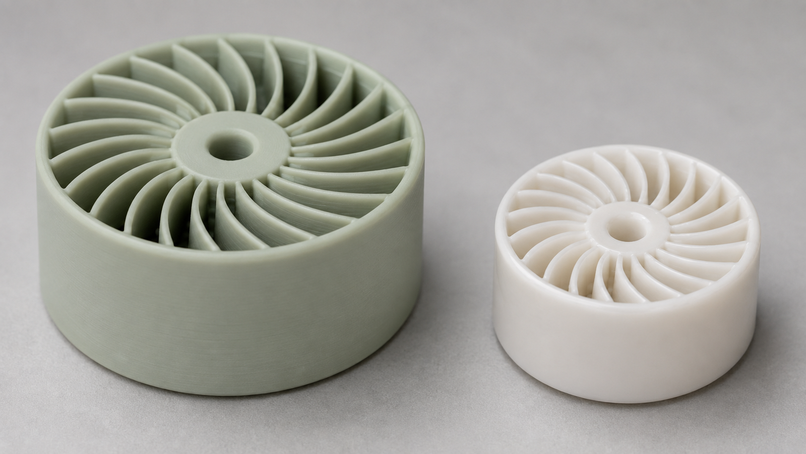
Scope: this section describes Path 1 — binder-based, sintering-densified parts. Because such a green part contains binder and porosity that the fired part does not, these printed ceramics shrink — substantially and by design. Linear sintering shrinkages commonly reported across routes and materials fall on the order of 10–25%, depending on solids loading, powder, binder system, and firing route.2,15 The workflow answer is pre-compensation: the green part is printed oversized by a calibrated scaling factor so the fired part lands on dimension. Three honest caveats keep that sentence from sounding too easy. Shrinkage is often not perfectly isotropic — layerwise processes can shrink differently in-plane versus through-thickness, so mature workflows calibrate direction-specific factors. It is material- and batch-sensitive — a factor is earned by measurement, not copied from a datasheet. And tolerance conversations change: as-fired precision reflects the whole chain, dedicated test artifacts exist to characterize it, and tight interfaces are commonly finish-ground after firing. A worked example makes the scaling effect easier to see: at 20% linear shrinkage the scaling factor is 1/(1−0.20) = 1.25, so a feature meant to fire at 40 mm prints at 50 mm in the green state — and a one-percentage-point error in the assumed shrinkage moves that fired dimension by roughly half a millimeter, which is exactly why factors are calibrated, not assumed. It is the same resolution-versus-tolerance discipline our precision guide preaches for every process.2,16
Try it: the green-part scaling calculator
The calculator below runs the pre-compensation arithmetic for a Path 1 part — binder-based and sintering-densified: pick a target fired dimension and a linear shrinkage, and it shows how large the green part must be printed. It is a teaching tool for the concept — real workflows use direction-specific, material-calibrated factors verified on test coupons.
Choosing between the routes
The decision usually resolves along three axes. Detail and density favor slurry DLP: fine features, smooth surfaces, and near-full fired density for demanding structural and precision parts.6,8 Size, quantity, and geometric freedom favor binder jetting: bigger envelopes, unsupported green geometry, and batch nesting — with density engineered per application.10 Material flexibility and research agility favor extrusion routes, which accept the widest range of pastes and loadings.11,14 Which technical ceramic to print — alumina, zirconia, silicon nitride, or silicon carbide — is its own decision with its own physics; our technical ceramics materials guide compares the families, and the applications and design-rules guide shows where each earns its keep — from dental zirconia to bioceramic scaffolds and beyond.17,18 And as everywhere in additive manufacturing, route economics resolve at your real quantity, size, and finish requirement — not in the abstract.19,20 When a project is ready for real parts, our ceramic 3D printing service runs the slurry-DLP route end to end — print, debind, sinter, and dimensional verification under one roof.
FAQ
1. Why do many 3D printed ceramic parts require debinding and sintering?
Many, but not all, ceramic AM routes first shape a particle–binder green body — and for those binder-based routes, sintering is where the material is actually made: binder chemistry leaves, particles fuse, and density and strength are created in the furnace. Infiltrated, reaction-bonded, and directly consolidated parts follow different models.2,1
2. How much do printed ceramics shrink?
For binder-based, sintering-densified routes: commonly on the order of 10–25% linear, depending on material, solids loading, and binder system — and often not perfectly equal in every direction. Workflows compensate by printing the green part oversized with calibrated, direction-specific scaling factors. Infiltrated, reaction-bonded, and directly consolidated parts follow different dimensional-change models entirely.2,15
3. Is ceramic DLP the same as resin printing?
The light engine is a close cousin, but the resin is a heavily loaded ceramic slurry, the printed part is a green body rather than a finished product, and the defining engineering — debinding schedules, sintering, shrinkage compensation — happens after the printer stops.5,6
4. Can binder jetting make fully dense ceramics?
Three different questions hide in that one. Sintered directly, jetted green parts generally start less densely packed than slurry-cured ones, so densities depend heavily on powder engineering and firing strategy. Infiltrated or reaction-bonded, the pores fill — but the result is a composite or reacted material whose identity and properties differ from a single-phase dense ceramic. And many binder-jetting applications deliberately keep controlled porosity as a feature. Where near-full single-phase density plus fine detail lead the requirements, slurry DLP is usually the shorter road.10,2
5. What is the hardest part of ceramic 3D printing?
Rarely the printing. Debinding discipline (which limits wall thickness), sintering control, and dimensional-change calibration are where projects succeed or fail — which is why an integrated print-to-fired-part workflow, with test coupons and measurement, matters more in ceramics than in almost any other AM family.15,16
References
This article is provided by ACS Material LLC for educational purposes. Shrinkage ranges, density figures, and process characterizations are typical of the routes and literature discussed in general; actual values are material-, formulation-, and workflow-specific, and cited demonstration results reflect the referenced studies rather than guaranteed outcomes. Shrinkage discussion and the scaling calculator describe Path 1 (binder-based, sintering-densified) parts only; infiltrated, reaction-bonded, and directly consolidated routes follow different dimensional and stress models. The calculator is an idealized, isotropic teaching model — real pre-compensation uses direction-specific, material-calibrated factors verified on test specimens. ACS Material operates a slurry-DLP ceramic printing service; coverage of binder jetting, extrusion, and lamination routes here is educational. Sample images are representative.