-
Dielectric Barrier Discharge (DBD): Reactors, Physics & Power
Jun 14, 2026 | ACS MATERIAL LLCThe dielectric barrier discharge (DBD) is the quiet workhorse of low-temperature plasma. By placing an insulator in the current path and driving it with alternating or pulsed high voltage, a DBD turns ordinary gas at atmospheric pressure into a cold, chemically active plasma — without ever collapsing into a hot arc. It is the discharge behind industrial ozone, large-area surface treatment, and the fast-moving field of plasma catalysis. This guide goes under the hood: the microdischarge physics, the discharge modes, the reactor geometries, and — crucially — how to measure and supply the power that drives one, with interactive simulators at every step.
Quick answerA dielectric barrier discharge is a gas discharge in which at least one electrode is covered by a dielectric (glass, quartz, or ceramic), driven by AC or pulsed high voltage. The barrier blocks direct current, so the discharge runs as a swarm of nanosecond micro-discharge filaments; charge deposited on the dielectric self-limits each filament and prevents an arc, keeping the plasma non-thermal even at atmospheric pressure. DBDs come in planar, coaxial, and packed-bed reactors; their deposited power is measured from the charge–voltage (Lissajous) figure; and they are matched to an application by the frequency, waveform, and pulsing of the power supply.
On this page- 1 What Is a Dielectric Barrier Discharge?
- 2 Inside the Microdischarge
- 3 Filamentary, Diffuse, and Glow Modes
- 4 Reactor Configurations
- 5 Measuring DBD Power: The Lissajous Figure
- 6 Power Supplies: Frequency, Waveform, Pulsing
- 7 Applications of DBDs
- 8 Process Parameters and Reproducibility
- 9 Conclusion
- 10 ACS Material Plasma Equipment
- 11 Frequently Asked Questions
- 12 References
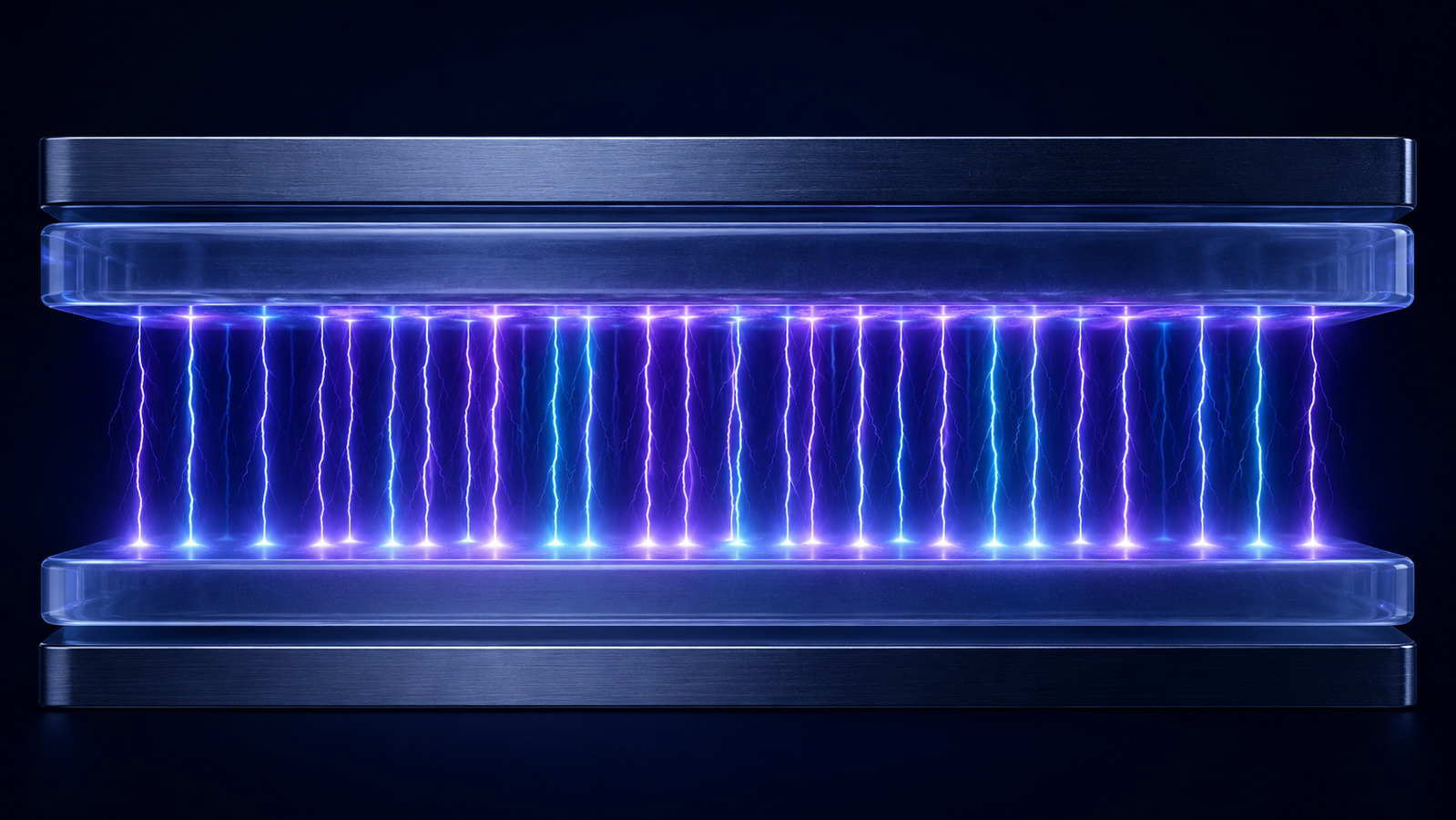
Figure 1. A dielectric barrier discharge: an insulating barrier between the electrodes forces an AC or pulsed drive and breaks the gas into many self-limited micro-discharge filaments, producing a cold plasma at atmospheric pressure. What Is a Dielectric Barrier Discharge?
A dielectric barrier discharge — historically also called a silent discharge — is a gas discharge in which one or both electrodes are covered by a layer of dielectric material such as glass, quartz, ceramic, or a polymer film.3 Because a dielectric cannot carry a steady (DC) conduction current, the cell must be driven by a time-varying voltage: alternating current from line frequency up to the megahertz range, or repetitive high-voltage pulses. When the applied voltage is large enough to break the gas down, the discharge does not develop into a single continuous channel. Instead it appears as a large number of short-lived micro-discharges, each lasting only a few nanoseconds and spread across the electrode area.13
The dielectric is the heart of the configuration. As soon as a micro-discharge forms, charge carriers drift to the dielectric surface and accumulate there, building up a local counter-voltage that opposes the applied field. Within nanoseconds this self-generated field cancels the gap field at that spot and the micro-discharge extinguishes itself — long before it can heat the gas or concentrate into a thermal arc.37 This self-limiting behavior is what lets a DBD operate stably at atmospheric pressure while remaining strongly non-equilibrium: the energetic electrons reach temperatures of a few electronvolts and drive chemistry, while the ions and neutral gas stay close to room temperature.1220 The simulator below shows a DBD cell igniting as the peak voltage is raised.
Inside the Microdischarge: Breakdown and the Memory Effect
Each individual micro-discharge (or filament) is itself a small, fast gas-breakdown event. At the millimeter gaps and atmospheric pressures typical of DBDs, breakdown usually proceeds by the streamer mechanism: a primary electron avalanche grows until its own space charge distorts the local field, launching a thin, fast-moving ionization front that bridges the gap in nanoseconds.819 The result is a narrow conductive channel, on the order of a tenth of a millimeter across, carrying a brief current pulse. In gases and gaps where avalanches stay small, a smoother Townsend-type breakdown can occur instead, and the discharge develops more uniformly — a distinction that underlies the different operating modes discussed in the next section.4
What makes the barrier discharge special is what happens after each filament. The charge it leaves on the dielectric does not simply disappear; it persists through the rest of the half-cycle and modifies where and when the next discharge forms. On the following voltage reversal, that deposited surface charge adds to the applied field, so the gas re-ignites more easily and often at the same spots. This is the famous memory effect of dielectric barrier discharges, first described in T. C. Manley's classic 1943 analysis of the ozonizer discharge, and it is central to both the stability and the modeling of DBDs.53 The accumulated charge also means that the voltage actually across the gas gap is not the same as the voltage applied to the cell — a fact that becomes essential when we measure power.
Filamentary, Diffuse, and Glow Modes
A DBD does not always look the same. In air and most molecular gases it operates in the filamentary mode: many independent micro-discharges strike at random positions and times, and the discharge current appears as a dense burst of sharp nanosecond spikes during each half-cycle.3421 This is the everyday behavior behind industrial ozone generators and large-area surface treatment, and it is the easiest regime to obtain.
Under more specific conditions — particular gases (helium is the classic example), small and uniform gaps, smooth electrode surfaces, and a clean driving waveform — the whole gap can instead break down as a single, spatially uniform discharge once per half-cycle. These diffuse or homogeneous regimes include the atmospheric-pressure glow discharge (APGD) and the atmospheric-pressure Townsend discharge (APTD), and they produce one smooth current pulse rather than a forest of spikes.47 A homogeneous DBD treats a surface far more evenly, which is valued for uniform activation and thin-film deposition; the trade-off is that it is harder to establish and to scale than the robust filamentary mode. The simulator below contrasts the two, in both the gap and the discharge current.
Reactor Configurations: Planar, Coaxial, and Packed-Bed
The same physics is packaged into several reactor geometries, chosen to match the job.37 In the planar (parallel-plate) configuration, a flat gas gap sits between two plates with the dielectric on one or both; it is simple, scales to large areas, and is the standard for treating flat substrates, films, and textiles. In the cylindrical (coaxial) configuration, a dielectric tube carries an outer electrode and an inner rod or coating, and gas flows through the annular gap to be processed continuously — the classic ozone-tube arrangement.
The packed-bed reactor fills the discharge gap with dielectric or catalyst pellets. Where the pellets touch each other and the wall, the applied electric field is strongly enhanced, and the discharge concentrates into those contact points and the voids between beads.9 Packing the bed with an actual catalyst places that field enhancement and the energetic electrons directly at the catalyst surface, coupling plasma and catalysis in the same volume. This is why the packed-bed DBD has become a widely used laboratory platform for plasma-driven CO₂ conversion, methane reforming, and nitrogen fixation.10112428 The simulator below lets you switch between the three geometries.
Measuring DBD Power: The Lissajous Figure
One of the most important — and most often mishandled — quantities in any DBD experiment is the power actually deposited in the plasma. Because a DBD is mostly capacitive, the apparent power drawn from the supply is dominated by reactive current that never reaches the gas. The reliable way to find the real dissipated power is the charge–voltage method: a known capacitor is placed in series with the discharge cell, the voltage across it gives the transported charge Q, and Q is plotted against the applied voltage V over a full cycle.56
For an idealized DBD this closed curve is a parallelogram, the Lissajous figure. Its two shallow sides (when no discharge is present) have a slope equal to the cell capacitance — the series combination of the dielectric and gas-gap capacitances. Its two steep sides (while the discharge is on) have a slope equal to the dielectric capacitance alone, because the conducting gas short-circuits the gap capacitance.6 The key result, derived by Manley in 1943, is that the area enclosed by the parallelogram equals the energy dissipated per cycle; multiplying by the driving frequency gives the deposited power.5 Below the breakdown voltage the loop collapses to a straight line of zero area — no discharge, no power. This equivalent-circuit picture, and the corrections needed when the discharge covers only part of the electrode, remain an active area of plasma diagnostics.6 The interactive Lissajous meter below lets you change the voltage and frequency and read the energy per cycle and the power directly.
Power Supplies: Frequency, Waveform, and Pulsing
Because the dielectric forbids DC, the power supply is the discharge: its electrical characteristics set the field, the current, and ultimately the chemistry. Three knobs matter most.31 Frequency — from line frequency through the kilohertz range — scales the number of discharge events per second and therefore, for a fixed Lissajous area, the deposited power. Voltage must exceed the gap breakdown value and then sets how much of the electrode area and gap participate. Waveform is the subtlest: a continuous sinusoid is the traditional drive, but pulsed excitation — microsecond or nanosecond high-voltage pulses — applies a much higher field for a very short time, which can raise the mean electron energy, improve the energy efficiency of a target reaction, and help maintain a more uniform discharge.134 The supply must also be matched to the largely capacitive load of the cell, which is why dedicated plasma power supplies are built around transformer and resonant designs rather than generic amplifiers.
ACS Material's plasma power supply line is built around exactly these variables. The CTP-2000K family provides low-temperature plasma experimental supplies in several excitations: a base CTP-2000K, a modulated-pulse version (CTP-2000K/P), a high-power version (CTP-2000K/A), a differential / low-pressure version (CTP-2000K/S), a microsecond-pulse version (CTP-2000KM), and a high-voltage low-frequency digital supply (CTP-2000KL) — so the excitation can be matched to the discharge. For the discharge cell itself, ACS Material offers dielectric barrier discharge experiment devices, a DBD reaction kettle, and a DBD coaxial reactor for flow-through processing.
Applications of DBDs
Ozone generation is the original and still the largest industrial use of the dielectric barrier discharge. Passing oxygen or dry air through a DBD dissociates O₂ and forms ozone, and the silent-discharge ozonizer that Manley analyzed in 1943 remains the basis of municipal water and air treatment today.532322
Surface activation and thin films. A brief DBD exposure cleans organic contamination, etches at the nanoscale, and grafts new chemical groups onto polymers, glass, metals, and textiles, dramatically changing wettability and adhesion without heating the bulk material.7 Running the discharge in a film-forming precursor extends this to plasma-enhanced chemical vapor deposition (PECVD) of functional coatings at atmospheric pressure.
Plasma catalysis and gas conversion. Combining a DBD with a catalyst — most often in a packed-bed reactor — drives chemical reactions at near-ambient temperature using electricity rather than heat.911 Energetic electrons activate stable molecules through vibrational and electronic excitation, opening reaction pathways that thermal catalysis reaches only at high temperature.1224 DBD reactors are among the most widely studied plasma platforms for CO₂ conversion into fuels and chemicals, dry reforming of methane to syngas, and nitrogen fixation toward ammonia or NOₓ — all candidates for storing renewable electricity as chemical bonds.101325262729
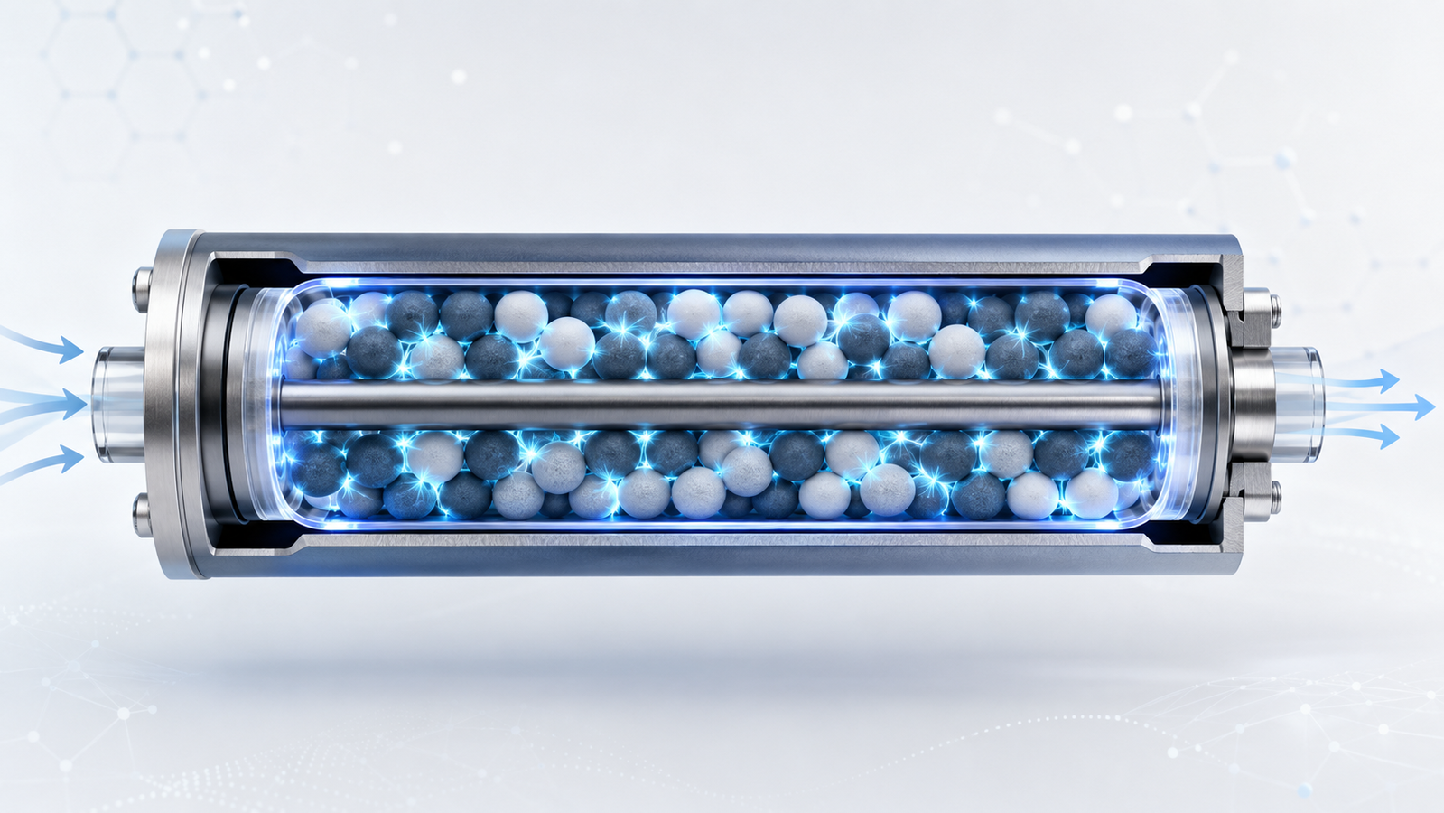
Figure 2. In a packed-bed DBD reactor, catalyst pellets fill the discharge gap and the electric field is sharply enhanced at every contact point, placing energetic electrons directly on the catalyst surface — the configuration behind plasma-driven CO₂ conversion, methane reforming, and nitrogen fixation. Decontamination and pollution control. The reactive oxygen and nitrogen species a DBD generates inactivate bacteria, viruses, and biofilms, including on heat-sensitive surfaces, and they oxidize volatile organic compounds and odors in air and persistent pollutants in water.1614 Related reagent-free, low-water processing is being explored across food and agriculture for surface decontamination and seed treatment.17 Biomedical and food applications remain device- and protocol-specific and require appropriate validation and regulatory clearance.
Nanomaterial synthesis. Non-thermal plasmas, including barrier and related discharges, are a solvent-free route to high-purity nanocrystals: the non-equilibrium environment selectively heats particles, while particle charging suppresses agglomeration and enables doping that is otherwise hard to achieve.1530
Process Parameters and Reproducibility
DBD chemistry is sensitive to many coupled variables, so reproducible results depend on recording them all. The parameters that most strongly shape the discharge and its chemistry are the gas composition and flow rate, the electrode gap, the dielectric material and thickness (which set the cell capacitances), the applied voltage, frequency, waveform, and duty cycle, the deposited power measured from the Lissajous figure, and the humidity, treatment time, and substrate temperature.63 Reporting the power as the charge–voltage area rather than the supply reading is particularly important, because two experiments at the same nominal voltage can deposit very different energy depending on the cell and waveform. Plasma systems also involve high voltage, ultraviolet emission, ozone and NOₓ production, and reactive exhaust, so they must be run with proper grounding, shielding, ventilation, interlocks, and gas-compatible materials, following the manufacturer's safety documentation.
Conclusion
The dielectric barrier discharge earns its central place in low-temperature plasma by doing something deceptively simple: an insulator in the current path turns a runaway gas breakdown into a controlled, self-limited, room-temperature plasma that can be scaled and shaped almost at will. From that one idea flow its microdischarge physics and memory effect, its filamentary and homogeneous modes, its planar, coaxial, and packed-bed reactors, and the charge–voltage method that quantifies the power it delivers. As renewable electricity becomes abundant and the 2022 Plasma Roadmap highlights electrified chemical synthesis and plasma-driven gas conversion as growth frontiers, the DBD — paired with a well-matched power supply — remains one of the most versatile and accessible tools in the plasma laboratory.18
ACS Material Plasma Equipment
ACS Material supplies a complete range of plasma power supplies and discharge cells for DBD research and process development — from cold-plasma experimental supplies to dielectric barrier discharge reactors and plasma jets.
- Plasma Power Supply (full category) — the complete CTP-2000K family and accessories.
- CTP-2000K Low-Temperature Plasma Experimental Power Supply — the base unit for DBD and cold-plasma work.
- CTP-2000K/P Modulated-Pulse Power Supply and CTP-2000KM Microsecond-Pulse Power Supply — pulsed excitation for higher peak fields and efficiency.
- CTP-2000K/A High-Power, CTP-2000K/S Differential / Low-Pressure, and CTP-2000KL High-Voltage Low-Frequency Digital supplies.
- Dielectric Barrier Discharge Experiment Device, DBD Reaction Kettle, and DBD Coaxial Reactor — planar and flow-through discharge cells.
- Plasma Jet Generator, Wide-Width Low-Temperature Plasma Jet, and Parametric High-Voltage Pulse Supply — for open-air and jet work.
Frequently Asked Questions
What is a dielectric barrier discharge?
It is a gas discharge in which at least one electrode is covered by a dielectric (glass, quartz, or ceramic) and driven by AC or pulsed high voltage. The barrier blocks DC current, so the discharge runs as many short-lived micro-discharges; charge building up on the dielectric self-limits each one and prevents a hot arc, keeping the plasma cold even at atmospheric pressure.
Why does a DBD need a dielectric barrier?
The dielectric carries no steady current, which forces the cell onto an AC or pulsed drive, limits the charge in every micro-discharge, and spreads the discharge over the whole electrode area. Remove the barrier and the discharge tends to constrict into a single hot arc; the barrier is exactly what keeps the plasma non-thermal and distributed.
Why must a DBD run on AC or pulsed voltage instead of DC?
Because a capacitor (which is what the dielectric makes the cell) passes no direct current. A changing voltage is needed to move charge through the dielectric and re-ignite the gas. In practice DBDs are driven by sinusoidal AC from line frequency to hundreds of kilohertz, or by repetitive microsecond or nanosecond high-voltage pulses.
What is the difference between filamentary and homogeneous (diffuse) DBD?
In air and most gases a DBD breaks down as many discrete filaments at random spots, giving a spiky discharge current — the filamentary mode. Under special conditions (often in helium, with small uniform gaps), the whole gap lights up as one smooth discharge per half-cycle — the homogeneous or glow mode, which treats surfaces more evenly but is harder to obtain and scale.
How is the power deposited in a DBD measured?
By the charge–voltage (Lissajous) method: a known capacitor in series with the cell gives the transported charge, which is plotted against the applied voltage. The closed curve is a parallelogram whose enclosed area equals the energy per cycle; multiplying by frequency gives the power. This is far more reliable than reading the supply, because most of the apparent power in a DBD is reactive.
What power supply do I need to drive a DBD?
A high-voltage source matched to the cell's capacitive load, with control over frequency and waveform. Sinusoidal kHz supplies are the general-purpose choice; modulated- or pulsed-output supplies give higher peak fields and can improve efficiency and uniformity. The ACS Material CTP-2000K family provides base, modulated-pulse, microsecond-pulse, high-power, differential, and high-voltage low-frequency variants for exactly this purpose.
What are DBDs used for?
The largest use is ozone generation; others include surface activation and PECVD coatings, plasma catalysis for CO₂ conversion, methane reforming and nitrogen fixation, sterilization and decontamination, air- and water-pollution control, and nanomaterial synthesis.
References
1 A. Fridman, Plasma Chemistry, Cambridge University Press, 2008. DOI: 10.1017/CBO97805115460752 M. A. Lieberman and A. J. Lichtenberg, Principles of Plasma Discharges and Materials Processing, 2nd ed., Wiley-Interscience, 2005. DOI: 10.1002/04717242543 U. Kogelschatz, “Dielectric-barrier discharges: their history, discharge physics, and industrial applications,” Plasma Chem. Plasma Process., 2003. DOI: 10.1023/A:10224709013854 R. Brandenburg, “Dielectric barrier discharges: progress on plasma sources and on the understanding of regimes and single filaments,” Plasma Sources Sci. Technol., 2017. DOI: 10.1088/1361-6595/aa64265 T. C. Manley, “The electric characteristics of the ozonator discharge,” Trans. Electrochem. Soc., 1943. DOI: 10.1149/1.30715566 A. V. Pipa and R. Brandenburg, “The equivalent circuit approach for the electrical diagnostics of dielectric barrier discharges: the classical theory and recent developments,” Atoms, 2019. DOI: 10.3390/atoms70100147 H.-E. Wagner, R. Brandenburg, K. V. Kozlov, A. Sonnenfeld, P. Michel and J. F. Behnke, “The barrier discharge: basic properties and applications to surface treatment,” Vacuum, 2003. DOI: 10.1016/S0042-207X(02)00765-08 S. Nijdam, J. Teunissen and U. Ebert, “The physics of streamer discharge phenomena,” Plasma Sources Sci. Technol., 2020. DOI: 10.1088/1361-6595/abaa059 E. C. Neyts, K. Ostrikov, M. K. Sunkara and A. Bogaerts, “Plasma catalysis: synergistic effects at the nanoscale,” Chem. Rev., 2015. DOI: 10.1021/acs.chemrev.5b0036210 R. Snoeckx and A. Bogaerts, “Plasma technology – a novel solution for CO₂ conversion?,” Chem. Soc. Rev., 2017. DOI: 10.1039/C6CS00066E11 A. Bogaerts, X. Tu, J. C. Whitehead, et al., “The 2020 plasma catalysis roadmap,” J. Phys. D: Appl. Phys., 2020. DOI: 10.1088/1361-6463/ab904812 A. Bogaerts, E. C. Neyts, O. Guaitella and A. R. Knoll, “Foundations of plasma catalysis for environmental applications,” Plasma Sources Sci. Technol., 2022. DOI: 10.1088/1361-6595/ac5f8e13 X. Chen, H.-H. Kim and T. Nozaki, “Plasma catalytic technology for CH₄ and CO₂ conversion: a review highlighting fluidized-bed plasma reactor,” Plasma Process. Polym., 2024. DOI: 10.1002/ppap.20220020714 H.-H. Kim, Y. Teramoto, A. Ogata, H. Takagi and T. Nanba, “Plasma catalysis for environmental treatment and energy applications,” Plasma Chem. Plasma Process., 2016. DOI: 10.1007/s11090-015-9652-715 U. R. Kortshagen, R. M. Sankaran, R. N. Pereira, et al., “Nonthermal plasma synthesis of nanocrystals: fundamental principles, materials, and applications,” Chem. Rev., 2016. DOI: 10.1021/acs.chemrev.6b0003916 X. Lu, G. V. Naidis, M. Laroussi, et al., “Reactive species in non-equilibrium atmospheric-pressure plasmas: generation, transport, and biological effects,” Phys. Rep., 2016. DOI: 10.1016/j.physrep.2016.03.00317 P. Bourke, D. Ziuzina, D. Boehm, et al., “The potential of cold plasma for safe and sustainable food production,” Trends Biotechnol., 2018. DOI: 10.1016/j.tibtech.2017.11.00118 I. Adamovich, et al., “The 2022 Plasma Roadmap: low temperature plasma science and technology,” J. Phys. D: Appl. Phys., 2022. DOI: 10.1088/1361-6463/ac5e1c19 P. J. Bruggeman, F. Iza and R. Brandenburg, “Foundations of atmospheric pressure non-equilibrium plasmas,” Plasma Sources Sci. Technol., 2017. DOI: 10.1088/1361-6595/aa97af20 A. Fridman, A. Chirokov and A. Gutsol, “Non-thermal atmospheric pressure discharges,” J. Phys. D: Appl. Phys., 2005. DOI: 10.1088/0022-3727/38/2/R0121 U. Kogelschatz, “Filamentary, patterned, and diffuse barrier discharges,” IEEE Trans. Plasma Sci., 2002. DOI: 10.1109/TPS.2002.80420122 U. Kogelschatz, B. Eliasson and W. Egli, “From ozone generators to flat television screens: history and future potential of dielectric-barrier discharges,” Pure Appl. Chem., 1999. DOI: 10.1351/pac19997110181923 B. Eliasson, M. Hirth and U. Kogelschatz, “Ozone synthesis from oxygen in dielectric barrier discharges,” J. Phys. D: Appl. Phys., 1987. DOI: 10.1088/0022-3727/20/11/01024 J. C. Whitehead, “Plasma–catalysis: the known knowns, the known unknowns and the unknown unknowns,” J. Phys. D: Appl. Phys., 2016. DOI: 10.1088/0022-3727/49/24/24300125 R. Snoeckx, Y. X. Zeng, X. Tu and A. Bogaerts, “Plasma-based dry reforming: improving the conversion and energy efficiency in a dielectric barrier discharge,” RSC Adv., 2015. DOI: 10.1039/C5RA01100K26 R. Aerts, W. Somers and A. Bogaerts, “Carbon dioxide splitting in a dielectric barrier discharge plasma: a combined experimental and computational study,” ChemSusChem, 2015. DOI: 10.1002/cssc.20140281827 A. Bogaerts, T. Kozák, K. van Laer and R. Snoeckx, “Plasma-based conversion of CO₂: current status and future challenges,” Faraday Discuss., 2015. DOI: 10.1039/C5FD00053J28 X. Tu, H. J. Gallon, M. V. Twigg, P. A. Gorry and J. C. Whitehead, “Dry reforming of methane over a Ni/Al₂O₃ catalyst in a coaxial dielectric barrier discharge reactor,” J. Phys. D: Appl. Phys., 2011. DOI: 10.1088/0022-3727/44/27/27400729 K. H. R. Rouwenhorst, Y. Engelmann, K. van ’t Veer, R. S. Postma, A. Bogaerts and L. Lefferts, “Plasma-driven catalysis: green ammonia synthesis with intermittent electricity,” Green Chem., 2020. DOI: 10.1039/D0GC02058C30 D. Mariotti and R. M. Sankaran, “Microplasmas for nanomaterials synthesis,” J. Phys. D: Appl. Phys., 2010. DOI: 10.1088/0022-3727/43/32/323001