
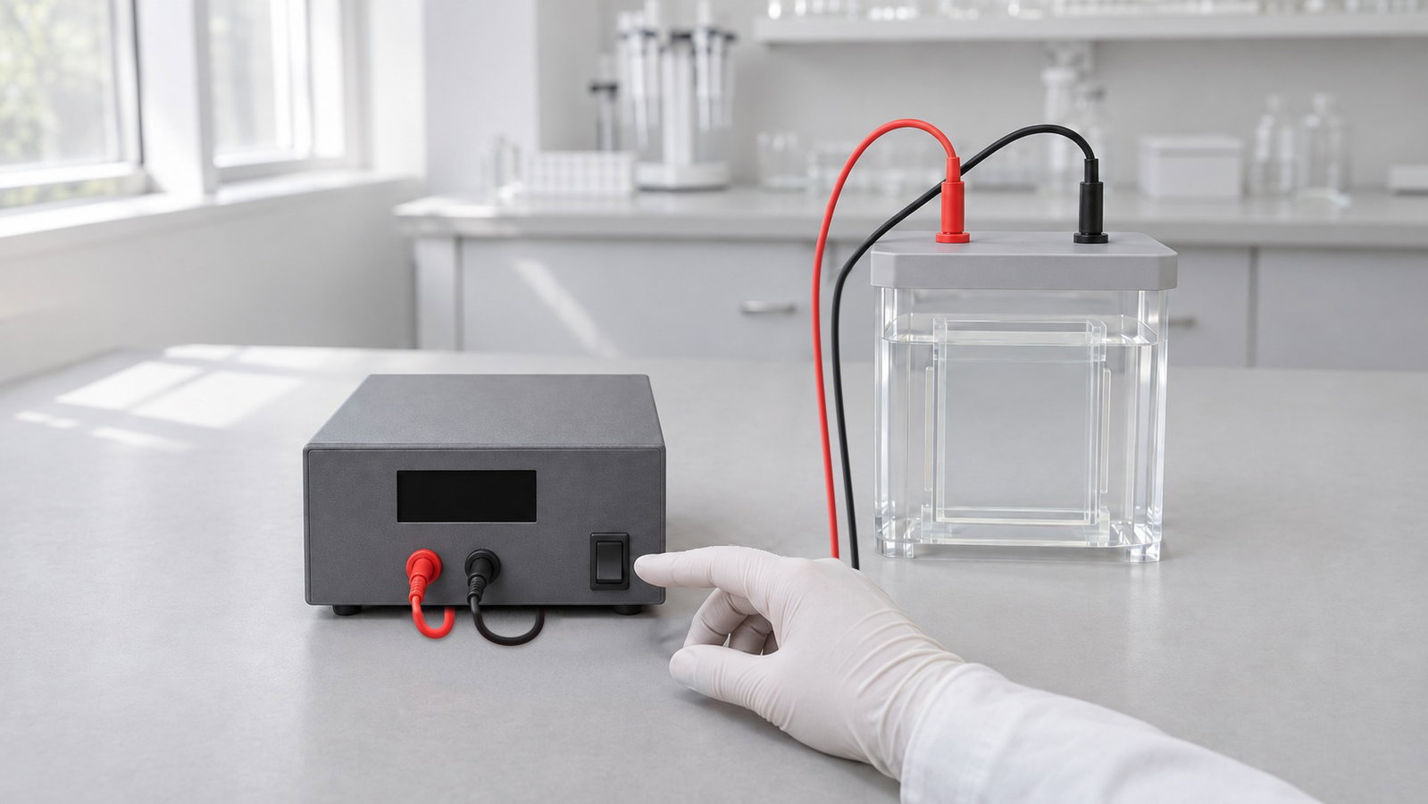
Choosing a gel electrophoresis voltage is really choosing three linked quantities: voltage, current and power. The gel and buffer set the resistance, Ohm's law ties the three together, and the mode you select decides which one stays fixed while the others drift during the run [1]. This guide explains constant voltage, constant current and constant power, how to turn a volts-per-centimetre guideline into a setting, why gels warm up and "smile", what a power supply's maximum ratings do and do not mean, and the basic electrical safety rules. For where the run sits in the wider bench workflow, see From Extraction to Gel Viewing: A Molecular Biology Bench Workflow with PCR, qPCR and Electrophoresis.
Quick answer:
- Multiply V/cm by the distance the source uses: Lee et al. give 1–5 V/cm between the electrodes, whereas Sanderson et al. define cm as gel length. QIAGEN and Thermo Fisher do not state a distance basis in the cited documents, so do not assume one [2–5].
- Constant voltage: holds the applied field steady; current and power change as resistance changes. One manufacturer recommends it for routine protein gels [1][6].
- Constant current: voltage rises as resistance rises, so set a voltage limit [1].
- Constant power: holds the heat output steady while migration speed changes; it is typically used for isoelectric focusing strips [1].
- Maximum ratings are separate limits: a supply cannot deliver its maximum voltage and maximum current together if their product exceeds its power limit.
1. Ohm's Law in a Gel
An electrophoresis cell behaves as a resistor. Voltage equals current times resistance (V = IR), and power equals current times voltage (P = VI), which can also be written I²R or V²/R [1]. The resistance depends on buffer conductivity, gel thickness, temperature and the number of gels in the circuit, and it changes during the run [1].
Charged molecules move at a speed proportional to the field strength, which is voltage per unit distance [1]. Current is a consequence of the buffer and gel: for a given system at a given temperature, it rises with the field and with the cross-sectional area carrying it, so thicker gels or more gels draw more current [1]. Power is the rate at which electrical energy turns into heat [1].
Calculated illustration, not a specification. Inputs: a hypothetical 100 V across a hypothetical 2,000 Ω gel and buffer. The current is 100 V ÷ 2,000 Ω = 50 mA, and the power is 100 V × 0.05 A = 5 W, all of it released as heat in the gel and buffer.
2. Constant Voltage, Constant Current or Constant Power
A power supply can hold one of the three quantities constant. The other two then follow the resistance. The choice of constant current vs constant voltage matters because resistance seldom stays put: in discontinuous protein gels such as Tris-glycine, resistance increases as highly conductive chloride ions are replaced by less conductive glycine ions, while warming lowers resistance [1]. In agarose gels run at constant voltage, current typically increases during the run as the buffer warms [5].
| Mode | What stays fixed | What happens as resistance rises | Practical notes |
|---|---|---|---|
| Constant voltage | Applied field strength (for a fixed electrode spacing) | Current and power fall as resistance rises | Provides a safety margin if the circuit breaks; the cited manufacturer guidance does not require changing the voltage setting solely for gel number or thickness in its described setup [1][6] |
| Constant current | Current | Voltage and power rise; migration starts slowly and speeds up | Favours stacking in discontinuous gels; set a voltage limit at or slightly above the expected maximum [1] |
| Constant power | Electrical output power | Voltage rises and current falls, so migration speed changes | Typically used for isoelectric focusing strips; set a voltage limit [1] |
Table 1. How each output mode responds when gel resistance rises [1][6].
Calculated illustration, not a specification. Inputs: the hypothetical 2,000 Ω load from §1 starting at 100 V, 50 mA and 5 W, with resistance rising to a hypothetical 2,500 Ω. At constant voltage, current falls to 40 mA and power to 4 W. At constant current, voltage rises to 125 V and power to 6.25 W. At constant power, voltage rises to about 112 V and current falls to about 45 mA. If instead resistance falls to a hypothetical 1,600 Ω at constant voltage, as when a buffer warms, current rises to 62.5 mA and power to 6.25 W, so the run heats faster as it warms.
Constant current has a specific risk. If a local fault such as a poor connection creates high resistance, the voltage can climb to the supply's maximum and overheat or damage the cell [1]. A voltage limit stops that climb. The same applies to constant power, where high local resistance can concentrate heat over a short distance [1].
3. Output Modes on the ALab DEP Series
The ALab™ DEP-300/DEP-600/DEP-300HC Electrophoresis Power Supplies offer constant voltage, constant current and constant power output, each continuously adjustable, with automatic mode switching. The outputs are set in steps of 1 V, 1 mA and 1 W, which is the setting resolution. Each model has an LCD touchscreen, multi-step programmes with tabular entry, a timer from 1 minute to 99 hours 59 minutes, and a USB interface. Check the operating manual for how the mode switching behaves on your unit before relying on it in a run.
4. Volts per cm for an Agarose Gel
For DNA in agarose, guidelines are usually given as field strength. One protocol programs the supply to 1–5 V/cm between the electrodes [2]; a bench guide gives 1–10 V/cm [3]; and one manufacturer's table suggests 5–10 V/cm in TBE for fragments below 1 kb, 4–10 V/cm for 1–5 kb, and 1–3 V/cm in TAE above 5 kb [4]. Voltage and run time are chosen together to reach the separation you need [7]. Very high voltage can cause trailing and smearing, particularly with high-molecular-weight DNA [3].
Definitions differ. The Lee protocol measures the distance between the electrodes [2], whereas Sanderson et al. define the centimetres as the length of the gel and note that gels 10–15 cm long are commonly run at 100–150 V for 50–90 minutes [5]. For a recommendation defined between electrodes, measure that gap in your own tank; for a recommendation defined by gel length, use the gel length instead. Where a source does not state its distance convention, do not infer one. Casting and percentage choices are covered in Agarose Gel Percentage and DNA Fragment Size: Choosing and Running a Horizontal Gel.
Calculated illustration, not a specification. Inputs: hypothetical electrode-to-electrode distances of 20 cm and 25 cm. The Lee protocol's electrode-gap range of 1–5 V/cm corresponds to 20–100 V across 20 cm and 25–125 V across 25 cm. The same voltage gives a weaker field in a longer tank, so a setting copied from another tank can run faster or slower than expected.
5. Joule Heating, Smiling and Band Distortion
Electrical power dissipated in the gel-and-buffer system appears as Joule heat [1]. In standard agarose gels, uneven heating distorts bands, and the size of the effect depends on gel geometry and buffer composition [5]. In Tris-based media, warming can increase conductivity and current under constant voltage, creating a positive feedback loop that limits the field strength standard buffers tolerate [8].
Heating is rarely even. Raising the voltage above common settings in standard TAE or TBE speeds migration but heats the gel and buffer unevenly, which broadens, slants and compresses bands and makes centre lanes run ahead of outer ones, known as "smiling" [5]. Current was lower with thinner gels and with less buffer over the gel, but agarose concentration did not affect it; the amount and type of EDTA and the buffer concentration did [5]. With modified gels and buffers, the same study ran gels at 20–25 V/cm [5].
Calculated illustration, not a specification. Inputs: hypothetical power of 5 W and 20 W for a hypothetical 30 minutes, into a hypothetical 500 mL of water-like buffer, with no heat lost. Heat equals power times time: 5 W for 1,800 s is 9.0 kJ and 20 W is 36 kJ. Using an assumed specific heat of 4.18 J/(g·°C) for this water-like buffer, these inputs give upper-bound temperature rises of about 4.3 °C and 17.2 °C in 500 g of buffer. Real tanks lose heat to the air and bench, so the rise is smaller, but the ratio shows why quadrupling the power matters.
| What you see | Likely cause | What to try |
|---|---|---|
| "Smiling", broad or slanted bands | Uneven heating across the gel | Lower the voltage; use a thinner gel and less buffer over it [5] |
| Smeared high-molecular-weight DNA | Field strength too high | Lower the voltage [3] |
| Current climbing and buffer warming at constant voltage | Heat–conductivity–current feedback in Tris buffers | Lower the voltage and check the buffer temperature during the run [3][8] |
| Gel melts during the run | Buffer wrongly prepared or exhausted | Remake the buffer; recirculate it in long runs [3] |
| Voltage climbs sharply at constant current | Rising resistance or a poor connection | Set a voltage limit; check leads and connectors [1] |
| Current falls during a constant-voltage protein-gel run | Resistance rises in a discontinuous system | This is expected; follow the protocol's endpoint rather than raising voltage solely because current falls [1] |
Table 2. Heating and electrical symptoms, with literature-based fixes.
6. Power Limits: Why Maximum Voltage and Maximum Current Are Not Available Together
A power supply has three separate output limits: voltage, current and power. Because power equals voltage times current, the maximum voltage and the maximum current cannot be delivered together when their product exceeds the power limit. Whichever limit the load reaches first takes control.
Calculated illustration, not a specification. Inputs: a hypothetical Supply X rated 0–500 V, 0–250 mA and 0–40 W. Multiplying its voltage and current maxima gives 125 W, more than its 40 W limit. At 500 V, the power limit caps the current at 80 mA; at 250 mA, it caps the voltage at 160 V. Below 640 Ω, Supply X reaches its current limit first; above 6,250 Ω, its voltage limit; between those values, its power limit is reached first. At exactly 640 Ω and 6,250 Ω, adjacent limits meet. Supply X is entirely hypothetical and does not represent any ALab power supply.
When you compare supplies, read the voltage, current and power ratings as three separate ceilings and check the operating manual for the combinations a unit can deliver at the same time. Table 3 lists the output ranges of the DEP series.
| Model | Output voltage | Output current | Output power |
|---|---|---|---|
| DEP-300 | 0–300 V | 0–600 mA | 0–150 W |
| DEP-600 | 0–600 V | 0–600 mA | 0–360 W |
| DEP-300HC | 0–300 V | 0–3000 mA | 0–400 W |
Table 3. DEP series output ranges.
| Model | Mains input | Weight |
|---|---|---|
| DEP-300 | 100–140 V / 195–245 V, 50/60 Hz | 1.90 kg |
| DEP-600 | 100–140 V / 195–245 V, 50/60 Hz | 1.96 kg |
| DEP-300HC | 100–240 V, 50/60 Hz | 2.05 kg |
Table 3b. DEP series mains input and weight.
The three output maxima in each row of Table 3 are separate limits; the voltage–current combinations available at the same time are not specified, so check the operating manual for the operating envelope. All three models measure 310 × 260 × 115 mm and have operating conditions of 0–40 °C and ≤95% humidity.
For the three models' output modes, timer and programming features, use View product / request a quote: ALab™ DEP-300/DEP-600/DEP-300HC Electrophoresis Power Supplies.
7. SDS-PAGE Voltage and Current
SDS-PAGE separates denatured proteins by size in a discontinuous polyacrylamide system: a stacking gel concentrates the sample before the resolving gel separates it [9–12]. Small-format vertical minigels are now typical [13]. Because resistance rises as glycine replaces chloride, the electrical behaviour drifts in a predictable direction during the run [1].
The SDS-PAGE voltage question usually comes down to two choices. At constant voltage, current and power fall as resistance rises, which the cited manufacturer guidance says reduces the risk of overheating [6]. The Novex guide also states that its voltage setting need not be adjusted solely for gel number or thickness [1]; this should not be read as a guarantee that every power supply can support any number of gels. At constant current, migration accelerates as the run proceeds and stacking is favoured, but the voltage rises and needs a limit [1]. One manufacturer's protocol for Tris-glycine minigels uses 125 V constant voltage for about 90 minutes, with the current falling from 30–40 mA at the start to 8–12 mA at the end, per gel [14]. Treat that as a reference point for those gels and buffers, not a general rule.
The ALab™ DL-MINI04 Vertical Electrophoresis Tank lists an SDS-PAGE electrophoresis time of 45 minutes at 200 V constant voltage. Gel percentage, buffer, gel thickness, sample load, current and temperature are not specified with that figure, so treat it as a starting point for that tank and confirm it against your own gels.
Transfer to a membrane after the gel is a different electrical problem. The electrodes are much closer together, so blotting uses a lower voltage, while the larger cross-section carries a higher current [1]. Transfer settings are covered in SDS-PAGE and Western Blot Transfer: Vertical Gels and Wet-Tank Transfer.
8. What Output Sockets Do and Do Not Tell You
The DEP series has four output sockets. A socket count alone does not tell you whether the outputs are controlled independently or how the output limits are shared between them.
The physics of connecting several loads to one output is general. Loads connected in parallel each see the same voltage, so at constant voltage the total current is the sum of the individual currents, and each gel runs as it would alone as long as the supply stays within its current and power limits. At constant current, the set current is shared between the loads in inverse proportion to their resistance, so the current per gel depends on how many gels are connected and how they differ. This circuit example does not establish that any particular supply is approved for multiple tanks or specify an allowed configuration; follow the manufacturer's manual for any approved connection arrangement.
Calculated illustration, not a specification. Inputs: two identical hypothetical 2,000 Ω loads connected in parallel to one output. At a constant 100 V, each draws 50 mA and the total is 100 mA. At a constant 50 mA total, each receives 25 mA, and that even split holds when the loads are identical.
9. Electrical Safety Basics
Electrophoresis equipment presents a serious electrical-shock hazard; university EHS guidance warns that even 100 V or less can deliver a lethal shock [15][16]. Replace frayed or damaged cords, and avoid spilling liquids into instruments [17].
Institutional procedures add practical rules. Inspect lead insulation and the chamber for cracks or leaks, and check that interlocks function without overriding them [16]. Before connecting or disconnecting any lead, switch off the main supply and wait 15 seconds, because voltage may remain on internal capacitors [16]. With the supply off, use dry gloved hands and handle one lead at a time using a single hand; keep the apparatus clear of unintended grounding points and conductive objects, and do not run it unattended [15][16]. Before opening the chamber cover, make sure the supply is switched off and the leads are disconnected; do not rely on safety interlocks [15][16].
The DEP series lists short-circuit protection, no-load protection, a buzzer that can be set, and a Power Failure Recovery function that can be switched on or off. These functions support, but do not replace, the safety rules above.
On the ALab™ DL-Mini01 Vertical Electrophoresis Tank (Double Plate), opening the cover cuts off the power. Even so, switch off the power supply before opening any tank.
10. Frequently Asked Questions
What voltage should I use for an agarose gel?
Multiply the guide's V/cm value by the distance that guide uses. The Lee protocol gives 1–5 V/cm between electrodes, whereas Sanderson et al. define cm as gel length; the cited QIAGEN and Thermo Fisher ranges do not specify the distance basis [2–5]. For a worked example, see §4.
Should I run SDS-PAGE at constant current or constant voltage?
Both are used. Constant voltage lets current and power fall as resistance rises, which, in one manufacturer's guidance, reduces the risk of overheating [6]; constant current favours stacking but needs a voltage limit [1].
Why does the current drop during my protein gel run?
In Tris-glycine gels, resistance rises as glycine replaces chloride, so at constant voltage the current falls [1].
Why does the current rise during my agarose gel run?
The buffer warms, its conductivity rises, and at constant voltage the current increases, which warms it further [5][8].
Why can't a power supply reach its maximum voltage and maximum current at once?
Because power equals voltage times current, the power limit caps one when the other is high (§6).
What happens electrically when multiple loads are connected in parallel?
In a parallel circuit, each load sees the same voltage and the branch currents add. Under current regulation, the total set current divides between branches according to their conductance; identical loads receive equal shares (§8). This circuit principle does not establish whether a particular electrophoresis supply supports multiple loads. Follow its manufacturer-approved wiring and operating limits.
11. Related Guides
- From Extraction to Gel Viewing: A Molecular Biology Bench Workflow with PCR, qPCR and Electrophoresis
- Agarose Gel Percentage and DNA Fragment Size: Choosing and Running a Horizontal Gel
- SDS-PAGE and Western Blot Transfer: Vertical Gels and Wet-Tank Transfer