
A hematocrit centrifuge provides capillary-rotor separation; a separate reading system assigns a packed cell volume (PCV) result. A packed-column length fraction is not automatically the volume fraction of unaltered red cells: residual material, cell-volume changes, tube geometry and boundary definitions can affect it. This guide compares the specified DM1424, DM1224 and D1524C configurations and explains those measurement limits. It supplies no sample-processing method or result interpretation.
Quick answer: Spun PCV estimates a red-cell volume fraction from a separated column. With a uniform bore and the specified boundaries, a length ratio represents a packed-layer volume fraction; it does not remove trapped fluid or correct cell-volume changes. Keep the centrifuge, tube, reading system and method definition distinct. AC24 is listed for DM1424/DM1224 and AC24P for D1524C; their shared maximum ratings do not establish interchangeability or a blood-processing setting. The calculations below illustrate measurement sensitivity, not clinical acceptability or verified instrument performance.
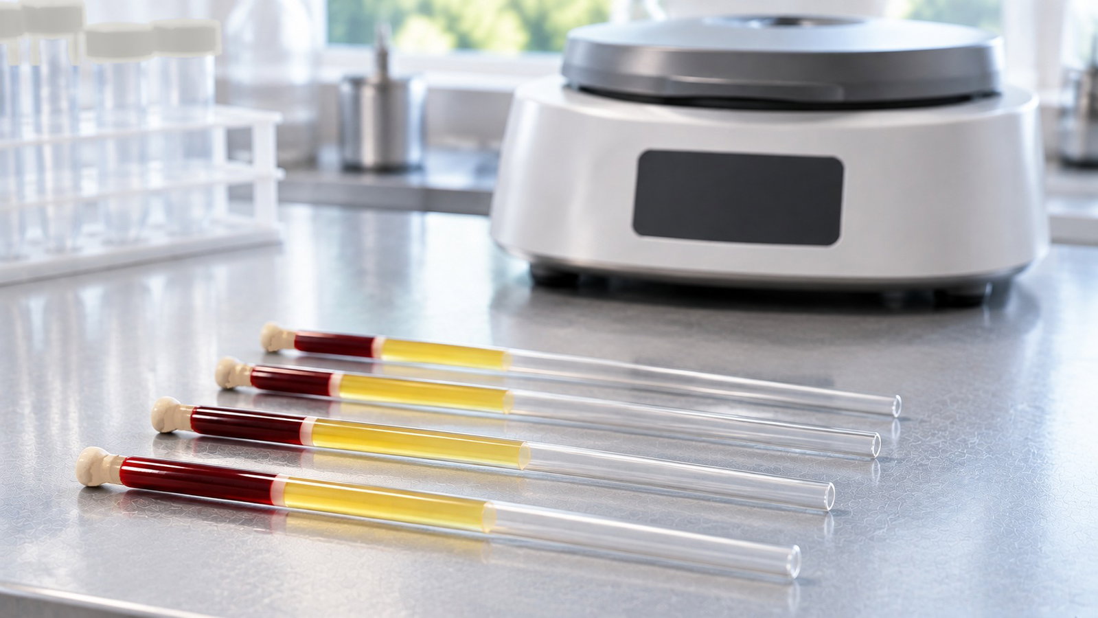
1. What the Packed-Column Measurement Represents
The intended quantity is a red-cell volume fraction. The spun method estimates it from a packed column, which can include residual fluid or other cells and can reflect cell-volume changes [1][4]. In the geometry examples below, f = 0.5 is an arbitrary midpoint, not a reference or decision value. It means half the measured column length is assigned to the packed layer. A fraction f written as a percentage is 100f%; both are dimensionless.
A length-based readout uses defined boundaries rather than directly measuring the original cell volume. The simplified model uses a lower sample/seal boundary, an upper boundary assigned to the red-cell-rich layer, and the plasma/air meniscus. A buffy coat can lie between the packed red-cell layer and plasma; the method must specify its treatment [4]. The operational ratio is
f = (assigned packed-layer length) ÷ (total sample-column length)
A uniform internal cross-section makes this ratio equal to the corresponding geometric layer-volume fraction in the idealized boundary model. It does not establish the volume of red cells before processing. Nonuniform area generally requires volume integration rather than length alone (Section 6).
"PCV" and "hematocrit" are often used for the same intended volume-fraction quantity. Some analyzers derive a result from cell count and mean cell volume rather than a spun length ratio [1]. Those are different measurement procedures; agreement must be established for the defined use, not assumed or universally ruled out. H07-A3 is a 2000 CLSI document archived in 2016; its public preview is not a complete review of the current procedure.
The historical ICSH reference and surrogate-reference publications [2][3] provide comparison frameworks for assessing measurement bias. Their laboratory procedures are outside this guide. A repeatable spun-column reading does not, by itself, demonstrate agreement with an independently established reference value.
2. Why Capillaries and High Force
Centrifugation can separate and compact suspended material, but the resulting layer is not an inert solid of fixed volume [4][6]. Bull and Hay discuss deformation, residual fluid and cell redistribution in their study [4]; these mechanisms are not a validated model for every sample or ALab configuration.
The specifications list 24 capillary positions, not the permitted capillary dimensions, seal, slot geometry or orientation. No loading direction or geometry is assigned to AC24 or AC24P here.
Two consequences follow.
Packing is method-dependent. Chaplin and Mollison reported condition-dependent trapped-plasma behavior in a particular historical method [5]. That does not supply a transferable force/time prescription. An apparently stable column length alone does not exclude residual fluid, cell-volume change or offsetting bias. Endpoint acceptance belongs to an established method, not a new spin series instructed by this article.
RCF varies with radial position. At fixed speed, RCF is proportional to perpendicular distance from the rotation axis: a point at 80% of another point's radius has 80% of its RCF. The ratio alone does not locate the ends of a real packed column. Chaplin and Mollison associated their observed trapping trend with effective centrifugation radius in their studied method [5]; no AC24/AC24P geometry is inferred.
3. The ALab™ Capillary-Rotor Configurations
Three models are compared. The table shows each model’s own specifications; a dash means the specification is not listed, not that the feature is absent. Rotor maxima are equipment ratings, not recommended sample conditions. Safety entries follow ACS Material’s specifications; this is not a complete safety-function or operating-manual review.
| DM1424 | DM1224 | D1524C | |
|---|---|---|---|
| Capillary rotor | AC24, 24 capillary tubes, high-strength aluminum | AC24, 24 capillary tubes, high-strength aluminum | AC24P, 24 capillary tubes; material not specified |
| Rotor rating | 12,000 rpm / 13,680 ×g | 12,000 rpm / 13,680 ×g | 12,000 rpm / 13,680 ×g |
| Speed range (step) | 200–12,000 rpm (10 rpm) | 500–12,000 rpm (100 rpm) | 200–12,000 rpm (100 rpm) |
| Speed accuracy | ±20 (unit not specified) | ±100 (unit not specified) | — |
| RCF handling | Speed/RCF switch; RCF step not specified | Speed/RCF switch; RCF step not specified | Rotation speed/RCF switchover; RCF step 10 ×g |
| Run time | 30 s – 99 min, or continuous | 10 s – 99 min, or continuous | 30 s – 99 min, or HOLD (continuous) |
| Acceleration / braking | 30 s up / 30 s down | 40 s up / 40 s down | 25 s up / 25 s down; acceleration/deceleration adjustable at 9 levels |
| Programs | — | — | Up to 9 stored programs |
| Safety (specifications) | Door interlock, overspeed detector, automatic internal diagnosis, automatic rotor identification | Door interlock | Dual door lock, over-speed detection, over-temperature detection with internal diagnosis |
| Rotor radius | — | — | — |
| Capillary tube size, sealing, reading device | — | — | — |
A few points about reading this table.
The DM1424 and DM1224 share a rotor listing, not every specification. Both use the AC24 rotor, but they have different speed increments, run-time ranges, ramp durations and safety features. The accuracy figures are ±20 and ±100 with no unit specified. Confirm the units and conditions before comparing actual speed or RCF accuracy; Section 4 gives conditional arithmetic only.
The D1524C is not the D1524. ACS Material assigns microtube/PCR rotor formats to the D1524 and the separate AC24P capillary rotor to the D1524C. Neither cross-host compatibility nor AC24/AC24P interchangeability is established by similar names or ratings.
AC24 and AC24P are listed separately. They have different names and host models, and whether they are interchangeable is not specified. Treat each as belonging to the models it is listed with.
The headline figures match, the details do not. All three are rated to 12,000 rpm and 13,680 ×g with their capillary rotor. That is the rotor's rated maximum, not a recommended setting. The force your method needs, and its run time, come from your validated procedure, not from the rating.
What is not specified. Radius, compatible capillary dimensions, sealing details and a reading-device specification are not listed. No reader is attributed to ACS here. Confirm the actual configuration and supplied items separately; an omission is not proof of absence.
4. Instrument Settings and Conditional Sensitivity
Speed, settings and timing describe the mechanical run, not the complete measurement uncertainty. Their effect on a column reading depends on the method and sample. The calculations here are sensitivity illustrations, not blood spin conditions or estimates of PCV error.
Conditional speed sensitivity. At an unchanged reference radius, RCF2/RCF1 = (N2/N1)2. The ±20 and ±100 accuracy figures have no unit specified. For illustration only, assume perturbations of 20 or 100 rpm about N0 = 12,000 rpm and scale the rated 13,680 ×g pair. These assumed perturbations are not confirmed accuracy specifications, total uncertainty or permission to operate above the specified maximum.
| Specified or assumed value | Trial speeds for arithmetic only | Calculated RCF change | Scaled 13,680 ×g reference pair |
|---|---|---|---|
| DM1424 entry ±20; assume rpm only for this example | 11,980–12,020 rpm | about ±0.33% | about 13,630–13,730 ×g |
| DM1224 entry ±100; assume rpm only for this example | 11,900–12,100 rpm | about −1.66% / +1.67% | about 13,450–13,910 ×g |
| D1524C accuracy not specified | Not calculated | Not calculated | Not calculated |
The arithmetic uses a fixed-reference ratio, not a measured radius. It does not resolve the missing units, demonstrate delivered RCF or supply a PCV uncertainty. D1524C's speed accuracy is not specified.
Setting increment is not accuracy. At fixed radius, the step from 11,990 to 12,000 rpm changes RCF by about 0.17%, and 11,900 to 12,000 rpm by about 1.7%, relative to each lower-speed value. A 10 ×g increment is about 0.073% of 13,680 ×g. These are calculated sensitivities, not actual RCF errors. Confirm the available input mode, capillary reference point and selectable settings; a switchover or step entry alone does not validate the displayed RCF.
A hypothetical ramp integral. For a chosen nonzero hold angular speed ωh, define E = ∫[ω(t)/ωh]2 dt in seconds. At a fixed reference radius, E is integrated RCF divided by hold RCF. A linear-speed rise from rest to ωh over T seconds contributes T/3, as does a linear return to rest. Using the listed durations gives the following mathematical examples, not verified profiles or equivalent packing times.
| Model / borrowed duration inputs | Sum of assumed ramp durations | Normalized ramp E (linear-speed model) |
|---|---|---|
| DM1424: 30 s up / 30 s down | 60 s | about 20 s |
| DM1224: 40 s up / 40 s down | 80 s | about 27 s |
| D1524C: 25 s up / 25 s down | 50 s | about 17 s |
Test speed, load, ramp endpoints, profile shape and timer convention are not specified. D1524C's 25 s figure is not assigned to a particular one of its nine levels. The calculations neither specify a hold nor justify replacing hold time with ramp E. Compaction and other sample changes are not predicted by this speed integral. Resolve the operating and method requirements independently.
The radius is not specified. The common rating pair gives reff = 13,680 ÷ (1.118 × 10⁻⁵ × 12,000²) ≈ 8.5 cm. This inferred effective radius is algebra only, not a measured dimension or a known point along the capillary. Equal rating pairs do not prove equal geometry. An applicable speed–RCF pair can be scaled at an unchanged configuration and reference point without separately knowing radius; that conditional arithmetic does not resolve the missing reference-point definition. Confirm the configuration and display basis before operational use.
Use the permitted loading pattern and balancing criteria for the complete capillary/rotor assembly. This article supplies no slot arrangement or mass tolerance; the listed capacity alone does not define them.
5. Reading the Column
The centrifuge and reading system have different roles. No reader is listed for any of the three models. Cards, mechanical readers or image-based measurements can implement a ratio, but their boundary rules and performance require separate evidence. The three coordinates below describe the model used for the uncertainty illustration, not a complete reading procedure.
Lower boundary. In this model z0 is the assigned sample/seal boundary, not the end of the glass. A sloping or curved seal requires a defined boundary convention; treating it as one coordinate is an approximation.
Upper packed-layer boundary. Bull and Hay located the leukocyte/erythrocyte interface in their study [4, p. 193]. That supports an attributed example, not a universal reading rule for every method or reader. Residual cells, fluid and an indistinct boundary can affect the assigned z1.
Upper sample boundary. The plasma/air meniscus is represented by z2. Curvature, viewing angle and the prescribed reading convention can affect that assignment; they are not automatically captured by a random-coordinate error model.
Let f = (z1 - z0)/(z2 - z0) and b = z2 - z0. The sensitivities to z0, z1 and z2 are (f - 1)/b, 1/b and -f/b. First-order propagation with equal independent coordinate standard uncertainties uz gives uf ≈ (uz/b)√[1 + f2 + (1 - f)2] [10, Eq. A-3]. The shared lower endpoint is included, not treated as two independent length errors. The table uses the arbitrary mathematical value f = 0.5; entries are standard uncertainties in fraction units, not confidence limits or acceptable errors.
| Assumed total column length b | uz = 0.1 mm | uz = 0.25 mm | uz = 0.5 mm |
|---|---|---|---|
| 50 mm | 0.00245 | 0.00612 | 0.0122 |
| 25 mm | 0.00490 | 0.0122 | 0.0245 |
These are assumed coordinate-localization contributions only. At fixed uz, halving b doubles uf; this is not advice to alter a specimen fill. An uncertainty of 0.0122 in fraction units is 1.22 percentage points, not 1.22% relative error. Correlated coordinates require covariance terms [10]. Boundary-definition bias, scale distortion, bore geometry and sample effects need separate assessment; the table is not a total uncertainty budget or a reader specification.
Bull and Hay used magnified interface measurements and discussed reading-card limitations [4, pp. 193, 196]; their setup is not a required reader specification. For a hypothetical output rounded to the nearest q = 0.01 fraction unit, rounding alone is bounded by ±0.005. If the rounding error is modeled as uniform, its standard uncertainty is q/√12 ≈ 0.00289 [10, Eq. A-7]. A card's printed interval does not itself establish effective reading uncertainty, and the same quantization contribution must not be counted twice.
6. Error Sources From the Literature
The literature reports effects that can shift spun readings in opposite directions. Bull and Hay observed partial compensation under their study conditions [4]. That is not proof of reproducibility, unbiased results or equivalent behavior in other tubes or centrifuges. The following are reported mechanisms and geometric considerations, not correction factors or product-performance claims.
| Effect | Reported or modeled direction | Evidence boundary | Source |
|---|---|---|---|
| Residual plasma in the packed layer | Can increase the assigned layer fraction | Depends on the studied method; no universal trapping correction | [4][5] |
| Other cells within the assigned layer | Can increase the reading | Inclusion and associated fluid are method-dependent | [4] |
| Incomplete compaction | Can leave a longer column | A stable length does not independently demonstrate absence of bias | [1][5] |
| Cell-volume reduction during centrifugation | Can decrease the reading | Reported mechanism, not a correction for an ACS rotor | [4][7] |
| Tube diameter and glass composition | Study-dependent | Tested diameter/material effects do not define a universal factor | [7][8] |
| Nonuniform bore | Either direction | Deterministic geometric example below | Calculation |
| Oxygenation state | Can alter results | In-vitro observation, not a handling instruction | [9] |
| Boundary assignment and reader behavior | Either direction | Localization uncertainty and systematic effects must be distinguished | [4][10] |
Tube diameter and material. Karlow and colleagues reported lower spun readings with decreasing bore and a larger dehydration effect in their tested soda-lime than borosilicate tubes [7]. Solomon and Grindon reported about one volume percentage point between the small and large tubes they compared [8]: approximately 0.01 in fraction units, not 1% relative error. These are study-specific observations, not universal corrections, tube recommendations or findings for AC24/AC24P. Tube type and lot remain part of the documented measurement system.
Bore uniformity. Assume a straight filled tube with normalized axial coordinate x from the lower boundary (0) to the meniscus (1), and diameter d(x) = d0(1 + εx). If the assigned packed-layer length fraction is 0.5, its geometric volume fraction is FV = ∫00.5(1 + εx)2dx / ∫01(1 + εx)2dx. For ε = +0.05, FV ≈ 0.4878; for ε = -0.05, FV ≈ 0.5128. Thus the length ratio 0.5 differs by about +0.0122 or -0.0128, respectively. With ε = ±0.02, FV is about 0.49505 or 0.50505. These are deterministic results for an assumed taper, not tube tolerances, uncertainty estimates or original red-cell volume fractions.
Oxygenation. Bryner and colleagues reported changes in spun and analyzer-derived quantities with in-vitro oxygenation state and proposed water shifts and hemoglobin conformational changes as likely contributors [9]. The observation is a potential source of method dependence; no oxygenation or specimen-handling procedure is prescribed here.
Sample representativeness. The measurement applies to the examined aliquot under the method's conditions. Collection, anticoagulation, mixing and other specimen-processing instructions are outside this article; equipment specifications do not resolve those requirements.
7. What a Packed Cell Volume Can and Cannot Tell You
Taken together, the physics sets clear limits on the number.
- It is method-defined. Tube, preparation, mechanical conditions and boundary conventions can affect the result; their magnitude is not predicted by this article.
- It is not automatically pure cell volume. Residual material and cell-volume changes can bias a spun estimate relative to a reference approach [2][3][4].
- Agreement is an evidence question. A spun ratio and an analyzer-derived result use different procedures; neither equivalence nor universal non-interchangeability follows from their names.
- Geometry matters. A length ratio represents the geometric layer-volume fraction in a uniform-area idealization; it does not remove biological bias.
- Mechanical specifications are not an uncertainty budget. Speed, timing, reading, tube and sample contributions require separate assessment.
What the number means for any person or animal it came from is a clinical question. This guide does not address it, and no reference values are given here.
8. Evidence to Check for the Measurement System
The following are documentation questions, not instructions to collect, process, respin or interpret a blood specimen.
- Instrument evidence: Are units, operating limits, timing conventions and required calibration/service records established? Use authorized verification arrangements; do not improvise access to a rotating rotor.
- Method evidence: Is the measurement endpoint and its suitability already established in the applicable method? This article supplies no plateau experiment or blood spin force/time.
- Consumable evidence: Are capillary dimensions, material, lot and compatibility documented, with changes assessed under the quality system [7][8]?
- Reading evidence: Are boundary conventions, scale behavior, bias, resolution and uncertainty characterized? A known-length check alone does not validate the entire ratio measurement [10].
- Repeatability evidence: Is adequate repeatability information available? Agreement between two readings does not exclude shared bias or establish total uncertainty.
- Traceability: Can the instrument, AC24 or AC24P host, tube, settings, method and reading system be identified without assuming interchangeability?
9. Frequently Asked Questions
What is a hematocrit centrifuge?
A centrifuge designed for capillary-rotor separation associated with packed-column measurements. The DM1424, DM1224 and D1524C listings each specify a 24-place capillary rotor rated to 12,000 rpm and 13,680 ×g. Those are rotor ratings, not processing conditions or demonstrated PCV accuracy; reading requires a separately defined measurement system.
Is packed cell volume the same as hematocrit?
The terms often refer to the same intended volume-fraction quantity. A spun-column estimate and an analyzer result derived from cell count and volume use different measurement procedures and can have different biases [1]. Their agreement has to be established for the defined use, not assumed from terminology.
Why do the DM1424 and DM1224 differ if they use the same rotor?
Both use the AC24 rotor, but they have different speed increments, run-time ranges, ramp durations and safety features. The accuracy figures ±20 and ±100 have no units specified. The rpm interpretation in Section 4 is only a hypothetical sensitivity calculation until the units and conditions are confirmed.
Can the D1524 run capillary tubes?
The AC24P capillary rotor is listed for the D1524C only, and tube rotors for the D1524. Compatibility between them is not specified, so do not assume it.
Is a reading device part of these listings?
None is listed for the DM1424, DM1224 or D1524C. The reading method and its calibration are separate from the centrifuge and are set by your own procedure.
10. Keep Exploring Centrifugation
- Laboratory Centrifugation: RCF, Rotors, Sedimentation and How to Choose a Centrifuge: the centrifugation hub covering RCF, rotors, sedimentation, temperature, safety and the full series of guides.
Capillary-rotor models: DM1424 and DM1224 Hematocrit Centrifuges and the D1524C Hematocrit Centrifuge.
Browse all ALab™ centrifuges.