
A laboratory centrifuge rotates samples to create a strong radial acceleration that can separate suspended components according to their sedimentation behavior. Dense particles may move outward relative to a less-dense medium, while less-dense components can move inward; the outcome depends on the complete sample and run conditions. Applications include microtube spin-downs, particle collection, and capillary packed-layer measurements. This guide introduces the principles, maps the nine ALab™ centrifuges, and directs readers to the dedicated technical guides; it does not validate a method for any model.
Quick answer: A laboratory centrifuge uses rotation to produce radial acceleration. RCF (×g) at a specified radius is calculated as 1.118 × 10⁻⁵ × r × N², where r is in centimeters and N is in rpm. Separation depends on density difference, shape, viscosity, sample concentration, geometry, actual speed history and the measurement endpoint. Screen centrifuges by documented tube/rotor/adapter compatibility, the rated force of that configuration, capacity and temperature requirements; then check loading, controls and safety in the applicable instructions. A headline rating alone does not validate a run.
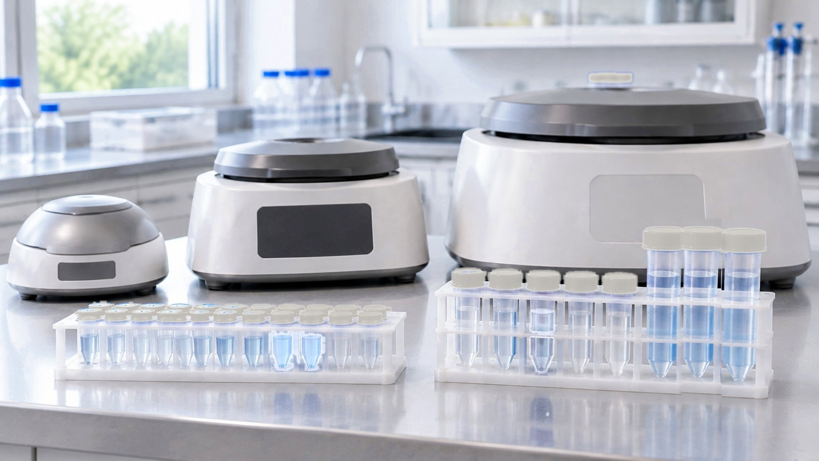
1. How a Laboratory Centrifuge Works
In the rotating frame a sample experiences outward centrifugal acceleration of magnitude ω²r, where ω is angular speed and r is the distance from the rotation axis. A component whose effective density exceeds that of its medium may migrate outward relative to the liquid; the direction and rate of separation depend on buoyancy, drag, shape, concentration and elapsed speed history. Material collected at an end or wall may be called a pellet and the remaining liquid a supernatant, but collection geometry and the appearance of separated phases are method-dependent. The terms are descriptive, not a guarantee of pelleting or layering.
Four things therefore define every run:
- Force: how strong the acceleration is, expressed as RCF in multiples of g.
- Time: how long the sample spends at that force, plus whatever sedimentation happens while the rotor speeds up and slows down.
- Geometry: where in the rotor the tube sits and how far a particle has to travel before it reaches the pellet.
- Conditions: temperature, which changes the liquid's viscosity and can affect the sample itself, and the liquid's density.
Centrifuges can be grouped editorially by specified tube configurations, acceleration ratings and operating controls. The labels below overlap; they are not formal, exclusive classes or performance rankings.
- Palm or mini centrifuges are illustrated in this range by the D1008's specified microtube and PCR formats and single operating point; a general class label does not establish every unit's capacity or controls.
- Low-speed benchtop centrifuges include configurations for several tube formats; the DM0412, DM0506 and Q0408E do not all have specified 50 mL compatibility. Check each rotor and adapter rather than inferring a tube fit from the class name.
- High-speed microcentrifuges in this range list specific microtube, 5 mL and PCR configurations with rotor-dependent ratings; those formats do not by themselves establish suitability for any precipitate or nanoparticle sample.
- High-speed centrifuges with interchangeable rotors cover microtubes, conical tubes, plates and large bottles in one instrument, each rotor with its own rating.
- Hematocrit centrifuges spin sealed capillary tubes in a dedicated capillary rotor.
- Ultracentrifuges reach far higher forces in an evacuated chamber. They are outside the scope of this series.
Any of these may be refrigerated. Refrigeration is a separate decision from speed class, covered in Section 5.
2. RCF: Describe the Force, Not the Speed
Rotational speed in rpm says how often the rotor turns. Relative centrifugal force says how hard the sample is pushed, as a multiple of standard gravity (g = 9.80665 m/s²) [1]. Methods should specify RCF, because the same rpm produces different forces in rotors of different size.
The conversion follows from the centripetal acceleration ω²r with ω = 2πN/60:
RCF = 1.118 × 10⁻⁵ × r × N², with r in centimeters and N in rpm [2][3].
Two consequences matter at the bench:
- Force scales with the square of speed. At a fixed radius, 10 % more speed gives about 21 % more force, and halving the speed quarters it.
- Force scales linearly with radius. At the same speed, a tube seated farther from the axis feels proportionally more force.
ACS Material rotor tables show both effects. The DG1616 / DG1616R has a specified radius for each rotor. Its AS30-2 microtube rotor is listed at 10 cm, 16,000 rpm and 28,620 ×g; its SR4-400 large-bottle rotor at 16.6 cm, 5,000 rpm and 4,639 ×g. If both were run at the same 4,000 rpm, a speed within both ratings, the formula gives about 1,789 ×g at 10 cm and about 2,969 ×g at 16.6 cm. The DM0412 shows the same effect within one rotor: its A12-10P configuration is specified at 11 cm and 2,490 ×g at 4,500 rpm for tubes seated directly, and at 9.8 cm and 2,218 ×g with the A10P15 adapter and plug for shorter tubes, about 11 % less force at the same speed.
An rpm value without a radius or applicable speed–RCF relation does not independently define the force. A specified speed–RCF pair can support conditional scaling only for the same configuration and radius basis; it does not supply the missing tube/adapter geometry. An instrument's ×g setting or display is not independent verification of its radius convention. Confirm the complete configuration and source limits before transferring a method.
For the formula, radius conventions and a static conversion table, see RPM to RCF (×g) Conversion: The Formula, Rotor Radius and a Static Table.
3. Rotors, Radius and Path Length
The rotor decides three things: which tubes fit, the maximum speed and force they may see, and the path a particle takes through the liquid.
Two classic geometries
Textbooks describe fixed-angle and swinging-bucket designs as general principles [2][3]. In a fixed-angle design, a tube remains tilted relative to the rotation axis; radial transport may meet an outer wall before material moves or accumulates further. In a swinging-bucket design, a bucket pivots toward a near-horizontal operating position; the sample's path and the resulting layer or deposit depend on its liquid boundaries and operating geometry. Neither wall contact nor an extended path guarantees a finished pellet, faster clearing or cleaner layers. No ALab rotor is classified as either geometry in this article.
Which geometry a particular rotor has is a fact to read from the manufacturer's documentation, not to infer from a rotor's name, code or photograph. ACS Material does not classify any ALab™ rotor as fixed-angle or swinging-bucket, and this guide does not assign either label. The DG1616 / DG1616R rotor table, for example, lists the SR4-200 and SR4-400 with hanging cups, lids and handles, describes the SE4-100, a standard accessory, as a four-bucket rotor with a separate radius for each bucket set, and lists an S2-MP rotor for microplates. Their geometry is not described further.
The radius is a property of the configuration
The RCF reference point for a specified radius is not specified unless ACS Material defines it; do not assume the specified value is r_max or the center of mass of a loaded tube. Adapters, plugs and bucket configurations can change the applicable radius, but their effects require configuration-specific information. DG1616 / DG1616R lists SE4-100 bucket-set radii of 14–16.5 cm with corresponding 4,000 rpm ratings of 2,500–2,950 ×g. No adapter-specific radius or RCF is specified for the DM0506; its rotor maximum must not be transferred to an adapter without confirmation.
Path length and the k-factor
In an ideal radial-column model the k-factor is k = 2.533 × 10¹¹ × ln(r_max/r_min) / N², with N in rpm and endpoints defined for that model. For an unchanged applicable sedimentation coefficient s expressed numerically in Svedbergs, t (hours) = k/s estimates ideal constant-speed transit [2][4]. A lower k implies a shorter model time under matched assumptions, not necessarily faster observed pelleting. The surface and tube bottom are not universal r_min/r_max endpoints in angled or partly filled tubes. Real k calculations require documented geometry, fill, speed history and conditions; none is derived for an ALab rotor here.
For hypothetical path-length and k-factor examples, see Fixed-Angle vs Swing-Bucket Rotors: Path Length, k-Factor and Pelleting Time.
4. Sedimentation Basics: What Sets How Fast Things Pellet
For an isolated rigid sphere moving at low Reynolds number in a dilute Newtonian liquid, Stokes drag can give a local terminal velocity relative to the medium. With a specified local radial acceleration, a constant particle–medium density difference and negligible Brownian/backflow, the illustrative model is [2]:
v = d² × (ρ_p − ρ_m) × a / (18 η)
where d is the particle diameter, ρ_p and ρ_m the densities of the particle and the medium, a the centrifugal acceleration (RCF × g) and η the viscosity of the medium.
Each term has a practical meaning:
| If you… | Sedimentation velocity | Time to pellet over the same path |
|---|---|---|
| Double the RCF | Doubles | About halves |
| Halve the particle diameter | Falls to one quarter | About four times longer |
| Reduce the density difference toward zero | Falls toward zero | Very long; a particle with zero density difference does not pellet |
| Cool water from 20 °C to 4 °C | Falls by about 36 % (viscosity rises from about 1.00 to 1.57 mPa·s [5]) | About 1.6 times longer |
| Double the path length at the same force | Unchanged | About doubles |
Idealized scaling only: isolated rigid no-slip spheres, creeping flow, fixed medium density and viscosity, constant acceleration at the comparison point, and unchanged path, with no diffusion, wall, aggregation or concentration effects. The temperature row isolates viscosity and holds density contrast and other properties constant; it is not a complete cold-run prediction.
The sedimentation coefficient, s = v/(ω²r), can summarize migration under specified conditions and is expressed in Svedbergs (1 S = 10⁻¹³ seconds) [2][3]. It does not necessarily remain constant as particles aggregate or conditions change. When a corresponding k-factor, endpoint definitions and sample conditions are applicable, t = k/s provides a conditional ideal estimate—not a validated transfer of a separation method.
Three limits apply to every estimate:
- Shape and concentration. Stokes' law assumes isolated spheres. Rods, plates and aggregates sediment differently, and concentrated suspensions hinder each other.
- Brownian motion. For small particles, diffusion competes with directed sedimentation; actual recovery depends on the particle, field, time and geometry, and no universal size cutoff or perpetual suspension follows.
- The sample changes. Particles aggregate, cells deform and pellets compact during the run, so a calculated time is a starting point, not a method.
Differential centrifugation can separate fractions through successive sedimentation/collection steps, but what is retained depends on the sample and the specific procedure. Washing and redispersion are separate operations and may change the recovered material. Rate-zonal and density-gradient methods are distinct topics outside this hub; no universal spin sequence or particle-size cutoff is prescribed.
5. Heat, Refrigeration and Sample Temperature
A rotating rotor transfers mechanical energy to surrounding gas and the system through aerodynamic drag (windage) and other losses. Windage depends on speed, rotor geometry, enclosure and flow regime [3][6]; this guide does not estimate a model-specific heat rate or sample-temperature increase. Neither a brief low-speed run nor a prolonged high-speed run has a guaranteed thermal outcome from its speed class alone.
A refrigerated centrifuge offers a temperature-setting capability, but the setting does not establish the loaded sample's temperature history. A non-refrigerated machine may exchange heat with room air; an initially prechilled sample can temporarily remain below ambient, but controlled cooling of such a sample is not specified. Two ALab™ models have refrigerated temperature settings:
- D1524R: temperature setting −20 °C to 40 °C, with pre-cooling from room temperature to 4 °C in 7 minutes.
- DG1616R (the refrigerated DG1616 model): temperature setting −10 °C to 40 °C, cooling from room temperature to 4 °C in as little as 7 minutes. The DG1616 has no temperature setting.
The D3024 has a double cooling air design that forces air above and below the rotor. That is ventilation, not refrigeration, and no temperature setting is specified. The remaining models have no refrigeration specified.
A displayed setting, precooling figure and sample temperature are different quantities. The seven-minute specifications do not identify the rotor, load, initial conditions or sensing point needed to establish sample readiness. Use the applicable method's temperature requirements and an approved verification plan for representative loads rather than assuming prechilling or a single endpoint measurement is sufficient. Water's viscosity rises at lower temperature; this affects an ideal Stokes estimate when other quantities are held fixed, but does not predict a particular sample's pelleting time.
For heat generation, temperature settings and the sample-temperature evidence a method may need, see Refrigerated vs Non-Refrigerated Centrifuges: Windage Heat, Sample Temperature and When You Need Cooling.
6. Running a Spin: Balance, Acceleration, Braking and Safety
Balance by mass
Balancing is a requirement of the complete loaded configuration, not just equal nominal tube volumes. Correct loading may involve complete tube/adapter/bucket assemblies, mass distribution and approved placement patterns; a visually symmetrical or ideal mathematical ring is not automatically an approved rotor layout. No universal permissible mass mismatch is specified. Obtain the applicable instrument/rotor/tube/adapter instructions and measurement criterion before operation; do not infer an odd-count arrangement, mandatory blank opposite an arbitrary tube, or universal bucket-installation rule from the rotor's place count.
The D1524R has a rotor imbalance detection alarm, while the DG1616 / DG1616R has built-in dynamic balance detection with an automatic rotor imbalance warning. Threshold and response are not specified: neither automatic stopping nor acceptable loading can be inferred from a warning, an alarm, or its absence. See How to Balance a Centrifuge: Tube Placement, Mass Tolerance and Imbalance Detection for general principles and evidence limits; no ALab loading pattern is authorized here.
Acceleration and braking
A speed ramp contributes an integrated RCF history, but its duration alone does not reveal its shape or the instrument timer convention. Rapid deceleration can disturb some separations; the effect is sample- and configuration-specific, not a universal recommendation for one brake setting. DM0412 is specified with A12-10P 20 s up / 13 s down and A6-50P 20 s up / 20 s or 90 s down; these are listed times without a verified profile or gentle/standard mapping. DM0506 lists one acceleration and two deceleration settings, not their durations. Q0408E lists program memories and qualified segmented operation; no independent acceleration/braking settings are established, and segments are not braking profiles. Low-Speed Benchtop Centrifugation: Tube Formats, RCF, Acceleration and Braking examines this evidence without assigning an operating recipe.
Safety
IEC 61010-2-020:2026 is a published safety standard addressing electrically powered laboratory centrifuges [7]. Its publicly available description does not establish compliance, certification, or the full text of individual safety clauses for any ALab model. Listed safety features apply to the models they are listed for and are not a complete review of the operating manual. Confirm all limits of the complete instrument/rotor/tube/adapter assembly, the loading instructions and the permitted access/stop procedures; checking only rotor and tube RCF is insufficient.
7. How to Choose a Centrifuge: Four Questions in Order
Choosing a centrifuge means choosing a documented complete configuration. Headline speed, force and largest capacity may come from different rotors or conditions. The four questions below are a screening order; they do not replace the detailed product, rotor, tube and adapter comparison in How to Choose a Centrifuge: Tube Format, Capacity, RCF and Temperature Control or confirm method suitability:
- Which tubes? List every tube, strip, plate, capillary or bottle you will spin. A rotor either holds a format, directly or with a listed adapter, or it does not.
- How many per run? Record the required number and format, then check the approved loading pattern and any balancing assemblies; do not assume an extra blank is always required or sufficient.
- How much force? Take the RCF your method needs and check it against the rated maximum of the rotor, tube and adapter combination that holds your tubes, not the instrument headline. A high headline is no help if your tubes sit in a lower-rated rotor.
- How cold? If a method requires a particular sample temperature, compare the documented setting range and obtain evidence for the loaded sample's temperature performance under the intended conditions; a refrigerated setting alone does not prove it.
Then compare the remaining options on control features: whether force can be set directly in ×g, the speed step and accuracy, acceleration and braking options, stored programs and imbalance detection, exactly as ACS Material describes them. Where a figure is not specified, ask us before you order.
The overview below is a map of the nine products, not a substitute for the rotor-by-rotor, tube/adapter and feature comparison in the selection guide linked above.
8. Where the ALab™ Centrifuges Fit
The ALab™ centrifuge range covers nine products, including three model pairs. The table provides a concise orientation rather than the selection guide's rotor-by-rotor comparison. Ratings and temperature statements belong only to the model/configuration shown; the last column indicates where a product is cited as context, not proof of application performance.
| Model(s) | Group | Top rating (configuration it applies to) | Temperature control | Also an example in |
|---|---|---|---|---|
| D1008 | Palm spin-down | 7,000 rpm / 2,680 ×g, a single operating point on both rotors | — | Balancing; low-speed (as a contrast) |
| DM0412, in A12-10P or A6-50P configuration (not interchangeable) | Low-speed benchtop | A12-10P: 4,500 rpm / 2,490 ×g at 11 cm; A6-50P: 4,000 rpm / 1,800 ×g | — | Rotors; low-speed |
| DM0506 | Low-speed benchtop | 5,000 rpm / 2,600 ×g on both listed rotors; adapter-specific radius/maximum RCF not specified | — | Low-speed; balancing |
| Q0408E | Low-speed benchtop | 4,000 rpm / 1,860 ×g, single 8 × 15 mL rotor | No control specified | Low-speed |
| D3024 | High-speed micro | 15,000 rpm / 21,380 ×g, each of five listed rotors | No setting; forced-air cooling | Refrigeration; nanoparticles |
| D1524 (high-speed micro); D1524C (hematocrit) | High-speed micro; hematocrit | D1524: 15,000 rpm / 21,380 ×g, each of five listed rotors. D1524C: 12,000 rpm / 13,680 ×g, AC24P capillary rotor | — | D1524: refrigeration; nanoparticles. D1524C: hematocrit |
| D1524R | High-speed micro, refrigerated | 15,000 rpm / 21,380 ×g, each of five listed rotors | −20 °C to 40 °C | Balancing; refrigeration; nanoparticles |
| DG1616; DG1616R (refrigerated) | High-speed, interchangeable rotors | Headline 16,000 rpm / 28,621 ×g, from the AS30-2 (30 × 2 mL, 10 cm; rotor rated to 28,620 ×g); largest load 4 × 400 mL on SR4-400 (5,000 rpm / 4,639 ×g) | DG1616: temperature setting not specified; DG1616R: −10 °C to 40 °C setting | Rotors; balancing; refrigeration; nanoparticles |
| DM1424; DM1224 | Hematocrit | Both 12,000 rpm / 13,680 ×g on the AC24 capillary rotor | — | Hematocrit |
Source: ACS Material product specifications (October 2026). A dash means the specification is not listed. Editorial groups do not rank products or certify applications. Specified radii lack an identified reference-point definition unless noted. The final column lists topics where the products are cited as specification context, not validated uses. The selection guide gives the detailed comparison; the RPM-to-RCF guide discusses radius and conversion evidence.
Palm spin-down. The D1008 has microtube/PCR formats, two rotor options, a single specified 7,000 rpm / 2,680 ×g operating point and lid-activated operation without a specified user-set timer. Those facts make it a spin-down contrast, not evidence that every timed or lower-RCF method is unsuitable or that sample recovery is guaranteed.
Low-speed benchtop. These three models cover different configurations, not a shared 15/50 mL/evacuated-tube range. DM0412 offers non-interchangeable A12-10P and A6-50P configurations selected at quotation, with 50 mL listed only for A6-50P. DM0506 lists A6-15P and A4-50P and gives no separate adapter-specific radius/maximum RCF. Q0408E is specified only with its 8 × 15 mL rotor; no 50 mL rotor is listed. Tube geometry, dimensions and compatibility must be checked for the exact configuration.
High-speed micro. The D3024, D1524 and D1524R have the same five rotors for 0.2–5 mL tubes and PCR strips, each rated 15,000 rpm and 21,380 ×g. Among the three, only the D1524R has refrigeration and an imbalance alarm; the D3024 has forced-air cooling. Shared rotor lists do not mean shared features, so attribute each feature to the model it is listed for.
High-speed, interchangeable rotors. DG1616 and DG1616R share rotors covering microtube/PCR, bottle and microplate configurations. Radii are specified per rotor or bucket set, but their reference-point definitions are not specified. Its headline maximum RCF and largest listed bottle capacity belong to different configurations. DG1616R alone has a specified refrigerated temperature setting; no sample-temperature performance is inferred.
Hematocrit equipment. DM1424 and DM1224 share the listed AC24 capillary rotor and 12,000 rpm / 13,680 ×g maximum pair, but differ in speed range, setting increment, run time and safety wording. The specified speed-accuracy figures are ±20 and ±100 without units; do not silently add rpm. D1524C is separately listed with its AC24P rotor and rating and is not interchangeable with D1524's rotor set merely because they are listed together.
9. Two Specialized Applications
Nanoparticles and graphene oxide
Literature reports several different nanoparticle and graphene oxide sedimentation, washing and fractionation workflows, each dependent on material and experimental conditions; no universal force–time or size-cutoff recipe follows. A specified rpm without a radius or an applicable speed–RCF relation does not determine RCF for another configuration. Centrifuging Nanoparticles and Graphene Oxide: Washing, Size Selection and Redispersion compares published studies. This guide presents no ALab nanoparticle/GO centrifugation measurements, and ACS Material does not claim these applications; citing five high-speed model specifications is not evidence that any model washes, pellets, size-selects or redisperses those materials.
Hematocrit centrifuges and packed cell volume
A hematocrit centrifuge uses a capillary-rotor configuration to produce a packed column whose assigned layer length may be compared with the total sample-column length. For a uniform capillary bore, that ratio represents a geometric packed-layer fraction under the stated boundary convention, not a direct measurement of pure original red-cell volume. Residual fluid, other cells, bore geometry and reading uncertainties affect the interpretation. Hematocrit Centrifuges: Capillary Rotors, Packed Cell Volume and Measurement Limits discusses instrument specifications and measurement limits only; it provides no specimen-processing settings, diagnostic ranges or result interpretation.
10. The Centrifugation Guides in This Series
11. Frequently Asked Questions
What is a laboratory centrifuge used for?
Centrifuges can be used in methods that separate suspended components, clarify liquids, collect drops in tubes or produce capillary packed-layer measurements. The required configuration and endpoint depend on the sample and approved method; these are not verified performance claims for any particular ALab model.
What is the difference between rpm and RCF?
Rpm describes rotational speed; RCF describes radial acceleration at a specified radius in multiples of standard gravity. RCF = 1.118 × 10⁻⁵ × r × N² (r in cm, N in rpm). A stated rpm does not fix RCF without a radius or applicable speed–RCF relationship; record configuration, speed/RCF basis and relevant run conditions.
Does a higher maximum RCF mean a better centrifuge?
No. Headline RCF is tied to a stated configuration, and a different rotor or adapter may have a lower applicable limit. Select by documented tube/adapter compatibility, permitted speed/RCF, load and temperature requirements; a maximum rating by itself is not a method-performance comparison.
Why does my pellet take longer at 4 °C?
For idealized equal-density-contrast spherical particles in water, viscosity near 4 °C is about 1.6 times that at 20 °C; with other parameters held fixed this lowers a Stokes velocity by roughly 36%. It does not predict a particular pellet's run time or authorize higher speed. Confirm the sample's actual temperature requirements and method before changing conditions.
Is a fixed-angle or a swing-bucket rotor better?
Neither geometry is universally preferable. Wall interception in an angled design is not automatically completed pelleting, and a swinging-bucket design does not guarantee a flat interface or a particular recovery. Compare documented geometry and method requirements; no ALab rotor is assigned one of these labels here.
Do I need a refrigerated centrifuge?
A refrigerated setting may be necessary when a method specifies below-ambient conditions, but does not prove that every loaded sample reaches them. A short or low-speed spin is not automatically free of warming. Decide from the sample's temperature requirement and verified performance under the intended conditions, not from speed class alone.
Can I run a centrifuge with an odd number of tubes?
Possibly, but only when the specific rotor's approved loading scheme permits that count and the complete assemblies meet its balancing criteria. An extra blank or an evenly spaced ideal arrangement is not a universal permitted pattern. Use the operating instructions; never infer one from the number of rotor positions alone.
12. Keep Exploring Centrifugation
- RPM to RCF (×g) Conversion: The Formula, Rotor Radius and a Static Table: the conversion formula and a static table from specified rotor data.
- How to Choose a Centrifuge: Tube Format, Capacity, RCF and Temperature Control: the detailed comparison of nine ALab™ centrifuges.
- How to Balance a Centrifuge: Tube Placement, Mass Tolerance and Imbalance Detection: loading by mass and what imbalance warnings do and do not tell you.
All eight detailed centrifugation guides are linked in the question-to-guide map above.
Setting up a lab? See the Lab Equipment List for a New Research Lab. Working with graphene materials? See benchmark graphene oxide characterization and graphene nanoplatelets and dispersions.
Browse all ALab™ centrifuges.