Two plasma systems can sit side by side on a bench, run the same gas at the same power, and still be entirely different machines — because one drives its discharge with microsecond high-voltage pulses and the other with a 13.56 MHz radio-frequency sine. The excitation source is the deepest design choice in a plasma system. But it is set by two things, not one: the drive timescale, which decides which charged species can follow the field, and the coupling architecture, which decides how power actually enters the gas and whether a driven electrode sits in the plasma at all. This guide compares the four families a real selection comes down to — pulsed/kHz sources, RF capacitive (CCP), RF inductive (ICP), and microwave — and shows how to read a process requirement back to the right drive.
In one paragraph: at kHz-AC and microsecond-pulse timescales the field changes slowly enough that ions respond substantially, and each pulse or half-cycle can ignite a discrete transient discharge — the natural territory of atmospheric DBDs and jets, and of the ACS Material CTP-2000K family and parametric pulse supply. At RF (13.56 MHz) ions can no longer follow the oscillation; in a capacitive (CCP) reactor a quasi-steady glow forms behind thin sheaths at the driven electrodes, while an inductive (ICP) source couples power through a coil and a dielectric window — usually with no driven electrode immersed in the plasma — reaching very high densities. At microwave (2.45 GHz) power arrives through a waveguide or resonant cavity, again typically electrodeless. Pulse and kHz-AC excel at cold atmospheric processing; CCP owns ion-energy-controlled etching; ICP owns high-density low-pressure processing; microwave delivers dense, contamination-free plasma for demanding sources.
1. Frequency is only part of the story
The comparison starts with timescale. Electrons are light and respond to a changing field within fractions of a nanosecond; ions are thousands of times heavier and need microseconds to rearrange. So as the drive frequency climbs from kilohertz through megahertz to gigahertz, the plasma crosses a great threshold: the ions progressively stop following the instantaneous field.1,2 At kHz and pulse timescales, ions can respond substantially to the changing field — whether they traverse the full gap within a half-cycle depends on mobility, pressure, field strength, geometry, and pulse duration — and each pulse or half-cycle can ignite a fresh transient discharge. At RF, ions respond mainly to the time-averaged field while electrons oscillate and absorb power, so the discharge becomes quasi-continuous. At microwave frequencies, electrons follow the instantaneous field alone; ions still matter — they carry ambipolar transport, bombard surfaces, and do chemistry — but they answer only to averaged fields.3
Timescale, however, is only half the design. The other half is coupling architecture: whether power enters through driven electrodes across the gas (pulsed/kHz DBDs, RF-CCP), through a coil's induced field across a dielectric window (RF-ICP), or through a waveguide or resonant cavity (microwave). Architecture — not frequency alone — decides whether a driven electrode sits in the plasma, and with it the questions of sputtering, contamination, and ion-energy control.4 The same 13.56 MHz generator can feed a capacitive reactor or an inductive one, and they are different machines. That is why this guide compares four families, not three frequencies.
2. The source explorer
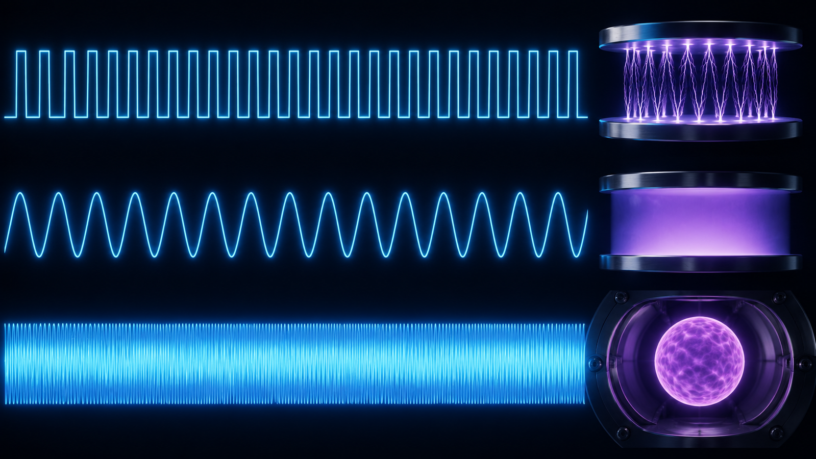
The simulator pairs each drive waveform (top) with the discharge it sustains (bottom): discrete transient filaments under microsecond pulses, a steady RF glow behind dark sheaths — the capacitive (CCP) form; inductive sources couple through a coil instead — and a cavity-coupled microwave discharge. Switch between them: the waveform-to-plasma pairing is the article in one frame.
3. Pulsed & kHz atmospheric sources
Kilohertz AC and microsecond pulsing are two dialects of the same language: deliver energy as discrete breakdown events. This is the native drive of the dielectric barrier discharge, whose self-quenching micro-discharges refresh every half-cycle,5,6 across every barrier arrangement from planar gaps to surface discharges.7 It is the drive behind most atmospheric-pressure non-thermal plasma generally — the regime where staying cold at full pressure is the entire point.8 One honest nuance: the events are discrete but not amnesiac. Surface charge left on the dielectric, metastables, residual electrons, long-lived species, and accumulated gas heating all create memory between events — each pulse ignites into the chemistry and charge state its predecessors left behind, which is precisely why the repetition-rate and duty-cycle controls covered in our frequency & duty-cycle tuning guide are real process variables.
Pulsing sharpens the trick. A fast-rising high-voltage pulse drives breakdown before the gas can heat, channeling energy into energetic electrons; in direct comparisons, pulsed excitation of a cold atmospheric jet produced markedly different discharge characteristics and efficiency than sinusoidal drive of the same device.9 Most atmospheric-pressure plasma jets — from research sources to the medical-grade kINPen — are driven in exactly this kHz-to-pulse territory,10,11,12 and so are the DBD systems behind cold-plasma food processing13 and plasma catalysis.14 This is the territory of the ACS Material line: the CTP-2000K (adjustable medium-frequency carrier), the CTP-2000K/P whose separate low-frequency modulator gates that carrier with an adjustable duty cycle, the microsecond-pulse CTP-2000KM, and the parametric high-voltage pulse supply for full waveform control.
4. RF-CCP: capacitive coupling
Cross into the megahertz range with two driven plates and you have the capacitively coupled plasma. At 13.56 MHz — the ISM-band frequency industry standardized on — ions drift in the time-averaged field while electrons do the fast work, and the discharge settles into a quasi-continuous glow separated from each electrode by a thin, dark sheath. The sheath is the CCP's defining asset: its average voltage drop accelerates ions onto adjacent surfaces with controllable energy, which is what makes capacitive reactors the precision tools of semiconductor etching and deposition.1 The electrodes are genuinely in the circuit — driven, sheath-screened, and subject to sputtering — a defining contrast with the inductive and microwave families below. Which discharge regime a given drive ignites is its own classification question; our companion guide to corona, glow, arc, and DBD discharge types maps that axis.
CCP diagnostics are a mature discipline with real subtleties — the electron energy distributions are non-trivial, and Langmuir probe practice in RF plasmas carries well-documented pitfalls.15 The application home turf is low-pressure surface engineering: etch, deposition, cleaning, and the plasma modification of polymers and biomaterials.16
5. RF-ICP: inductive coupling
Keep the 13.56 MHz generator but replace the plates with a coil wound around, or spiraled above, a dielectric window, and the machine changes character. The RF current in the coil induces an electric field inside the chamber that sustains the plasma — power now enters inductively, and there is usually no driven electrode immersed in the plasma at all. The consequences are large: inductively coupled plasmas reach ion densities beyond 1012 cm−3 even at sub-millitorr pressures — densities that rival or exceed other high-density sources — with far less electrode sputtering and contamination; the review that consolidated ICP physics for plasma processing remains a standard reference.17
ICPs (with their helicon and transformer-coupled relatives) are therefore the workhorse high-density, low-pressure sources of modern processing,3 and RF non-thermal plasma more broadly is a synthesis tool in its own right — nanocrystal growth in RF plasmas being a flagship example.18 Many practical ICP tools add a separately biased substrate electrode to control ion energy at the wafer — a deliberate hybrid, not a contradiction: the plasma generation is electrodeless, the ion-energy control is capacitive.
6. Microwave & surface-wave sources
At 2.45 GHz — the magnetron frequency — the coupling hardware changes again: power travels down a waveguide or builds up in a resonant cavity, and the family broadens into cavity discharges, surfatrons and surface-wave sources, and ECR systems. Like the ICP, microwave sources usually run with no driven electrode immersed in the plasma; electrons absorb the rapidly oscillating field directly, while ions respond to the time-averaged and ambipolar fields, bombarding surfaces and carrying chemistry as in any discharge. The result is a family of dense, low-contamination plasmas — and famously non-uniform ones, since the strongly inhomogeneous microwave fields shape the discharge; both the capability and the peculiarity are treated at length in the microwave-discharge literature.19
The price is coupling engineering: microwave power must be matched into a resonant structure, ignition shifts that resonance, and tuning is a real discipline. Where density plus purity dominate the requirement — diamond-film CVD, high-flux radical sources, demanding materials processing — microwave sources are frequently the answer.19
7. Compared: coupling, density & measurement
| Pulsed / kHz DBD | RF-CCP | RF-ICP | Microwave | |
|---|---|---|---|---|
| Coupling | Field across electrodes + dielectric | Capacitive, driven plates | Inductive, coil + window | Waveguide / cavity / surface wave |
| Driven element in plasma | Electrodes (behind dielectric) | Driven electrodes + sheaths | Usually none immersed | Usually none immersed |
| Field period | ~50 μs (20 kHz); μs pulses | ≈74 ns | ≈74 ns | ≈0.4 ns |
| Ion response | Substantial, waveform-dependent | Time-averaged only | Time-averaged only | Time-averaged only |
| Discharge character | Discrete transient events + memory | Quasi-steady glow + sheaths | Quasi-steady, high density | Continuous, cavity-shaped |
| Common operating range | Atmospheric | mTorr–Torr | Sub-mTorr–Torr | mTorr to atmospheric |
| Relative density | Low–moderate (transient) | Moderate | High (>1012 cm−3 reported) | High |
| System complexity | Lowest | Matching network | Matching + window design | Waveguide / cavity tuning |
| Home territory | Atmospheric DBD, jets, ozone | Etch, deposition, ion-energy control | High-density low-pressure processing | Diamond CVD, dense radical sources |
The pressure row lists common operating ranges, not physical boundaries — source architecture and application can extend well beyond these indicative windows. On density, note that no single family owns the crown: high-density ICPs reach ranges comparable to, or exceeding, microwave sources depending on pressure, power, magnetic configuration, and reactor design.
How each family is powered and measured. The drive dictates the honest power diagnostic. For barrier discharges and DBD-like cells — capacitive loads firing in nanosecond events — the charge–voltage Lissajous figure gives the energy per cycle, a method inherited from Manley's ozonizer analysis and still standard.20,21 Fast pulsed sources call for time-resolved voltage–current integration with careful displacement-current handling. RF systems are measured at the generator and matching network as forward and reflected power, supplemented by VI probes at the electrode. Microwave systems track incident and reflected power in the waveguide. Two caveats cut across all columns: quoted "electron temperatures" summarize distributions that are generally non-Maxwellian and differ between drive families,22 and the gas temperature your sample actually feels must be measured — rotational-line spectroscopy is the standard non-invasive route.23
8. Choosing the drive
Read your process backwards. Heat-sensitive surfaces at atmospheric pressure — polymer activation, biological samples, in-line treatment — point to kHz-AC and pulsed drive, the territory of the reactive-species chemistry behind plasma medicine and its relatives.24,25,26,27 Ion-energy-controlled, uniformity-critical low-pressure work points to RF-CCP; high-density low-pressure processing points to RF-ICP; maximum density with zero immersed electrodes points to microwave. Gas-conversion chemistry — CO2 splitting, plasma catalysis — is pursued across all four families, with the drive choice shaping energy efficiency,28,29 and the community's decadal roadmap is organized around exactly this diversity of sources.30
A transparency note on our own catalog: ACS Material's commercial line lives deliberately in the first column — kHz-AC and microsecond-to-parametric pulse supplies with matched DBD and jet hardware — because that is where atmospheric cold-plasma experimentation happens. We do not sell RF or microwave systems; the CCP, ICP, and microwave sections are here so you can locate our territory on the full map, and recognize when a requirement genuinely calls for a different family. If your process is atmospheric and non-thermal, tell us the sample and target and we will spec the supply, waveform, and cell.
Knowledge hub
- Plasma Processing Guide — the pillar overview of plasma, discharges, applications, and power supplies.
- Frequency & Duty-Cycle Tuning — the practical guide to carrier, burst modulation, and pulse controls.
- Discharge Types: Corona, Glow, Arc & DBD — what the drive ignites: the four common discharge categories.
- Parametric HV Pulse Supply — full waveform control for transient-discharge research.
- CTP-2000K Power Supply — the adjustable medium-frequency carrier at the heart of the line.
- CTP-2000KM Microsecond-Pulse Supply — sharp pulses for efficient, cool, species-rich discharges.
FAQ
Why do RF plasmas run at exactly 13.56 MHz?
It is a regulatory landmark, not a physics optimum: 13.56 MHz is an internationally reserved ISM (industrial, scientific, medical) frequency, so equipment there avoids interfering with communications bands. The physics — ions responding to averaged fields, electrons oscillating — holds across the low-megahertz range; the exact number is a convention the industry standardized its matching hardware around.
What is the difference between CCP and ICP plasma?
The coupling. A CCP drives plates capacitively: the plasma sits between driven electrodes, behind sheaths whose voltage drop gives precise ion-energy control. An ICP drives a coil whose induced field sustains the plasma through a dielectric window — usually no driven electrode immersed — trading direct ion-energy control for much higher density and lower contamination. Same generator frequency, different machines; many tools combine them, generating with a coil and biasing the substrate capacitively.
Do microwave plasmas need electrodes?
Usually no driven electrode sits in the plasma: power couples from a waveguide, cavity, or surface-wave structure directly into the electron gas. That eliminates most electrode sputtering and contamination, at the cost of more demanding coupling and tuning hardware. Antennas, ignition aids, and chamber walls still exist — "electrodeless" describes the drive, not an empty chamber.
What is a pulsed high-voltage supply actually good for?
Delivering energy faster than the gas can heat. A microsecond or sub-microsecond pulse drives breakdown and energizes electrons, then ends before significant gas heating — maximizing reactive chemistry per joule and keeping delicate samples cool. It is the sharpest tool in the atmospheric cold-plasma kit.
Can a kHz supply be turned into an RF or microwave source?
No. The families differ in transformer and switching architecture, in coupling (RF needs a tuned matching network; microwave needs waveguide or cavity coupling), and in the physics regime itself. A kHz/pulse supply like the CTP-2000K is engineered for transient capacitive discharges — a different machine from an RF generator, not a setting away from one.
Which excitation is best for atmospheric-pressure plasma?
Most accessible atmospheric cold-plasma work runs on kHz-AC and pulsed drive: the discrete, self-quenching discharges they ignite are what keeps an atmospheric plasma cold and stable. RF and microwave atmospheric sources exist — torches and some jets — but the sample-friendly atmospheric territory belongs overwhelmingly to the pulse/kHz family.
RF vs microwave — when would I move up?
When immersed electrodes become the problem: microwave sources run dense plasma with nothing driven inside the chamber, which is why diamond CVD and high-purity radical sources favor them. On density alone the case is weaker than folklore suggests — high-density ICPs reach comparable ranges — so the honest trigger is contamination and coupling geometry, not a density crown.