
Every plasma system hides the same uncomfortable arithmetic: the number on the generator's dial and the power actually entering the discharge are not the same number. The difference is reflected power — watts that bounce off an impedance mismatch and go back to heating cables and stressing the generator instead of making chemistry. Impedance matching is the engineering that closes that gap, and it looks completely different at different frequencies: motorized capacitors at 13.56 MHz, a resonant transformer and a frequency dial in the kHz world, tuning stubs at microwave. This guide walks the whole ladder — why a plasma is such an awkward load, where reflected watts physically go, how each frequency band solves the problem, and how to read the symptoms when the match is off.
In one paragraph: a plasma's impedance is nonlinear and drifts with power, pressure, and chemistry, while generators are built for a fixed load — so a tunable network must sit between them. Mismatch reflects power: the reference plane accepts forward × (1 − |Γ|²), the rest returns toward the source as standing waves, extra cable loss, and generator stress — and cable, matchbox, and electrode losses still take their cut before the plasma’s share. RF systems typically match with motorized (or manual) capacitor networks chasing the reflected-power null; kHz DBD supplies match by driving a transformer-plus-cell resonance — the reason specs read 0.5–2 × f₀, and the reason swapping reactors means retuning; microwave systems match with stub tuners and protect the source with circulators. Reflected power is the first meter to read, and delivered dose — not dial setting — is what your process actually feels.
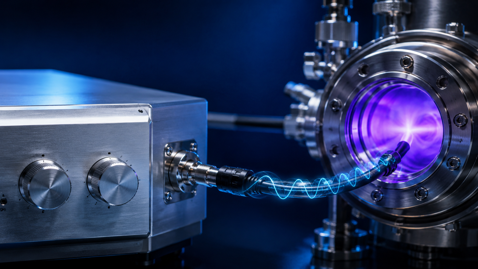
1. Why a plasma is a terrible load
Every power supply is designed around an assumption about what it will drive, and a plasma violates all of them. Before breakdown it is an open circuit; the instant it ignites, its impedance collapses by orders of magnitude; and as power, pressure, or gas composition move, the impedance keeps moving with them — discharge physics even hands parts of the operating curve a falling voltage–current characteristic, the opposite of a resistor's.1,2 A cold-plasma source, in other words, is a nonlinear, time-varying, state-dependent load.3 Meanwhile the generator on the other end of the cable was built to a fixed promise — for RF equipment, almost universally a 50 Ω resistive world of sources, cables, and connectors.4 Impedance matching is the machinery that reconciles the two: a tunable transformation network that makes the plasma, wherever it wanders, look like the load the generator was promised. Get it right and reflected power at the generator’s reference plane goes to zero — though even then, cables, matching components, and electrodes quietly take their cut before the plasma gets the rest. Get it wrong and the watts go somewhere else entirely — and this guide is about where.
2. The match tuner
The simulator below puts both matching worlds side by side. On the RF 13.56 MHz tab, two knobs stand in for a matchbox's tune and load capacitors: detune them and watch reflected power swell, a standing wave grow on the line, and the plasma dim — then hit Auto-tune and watch the servo find the null, exactly as a motorized matching network does. On the kHz AC tab, there are no knobs at all: the slider moves the drive frequency around the resonance of a transformer-coupled circuit, which is how mid-frequency supplies deliver their power — and why their front panels carry a frequency dial where an RF tool carries a matchbox.
3. Forward, reflected, absorbed: where the watts actually go
Connect a source built for 50 Ω to a load that is not, and part of the forward wave bounces at the boundary. The fraction is captured by a single number, the reflection coefficient Γ, and the bookkeeping is unforgiving: the load receives forward power × (1 − |Γ|²), and the rest travels back down the cable.5 The interference of forward and reflected waves prints a standing wave on the line — stationary voltage peaks that stress insulation and heat the cable — while the generator, seeing its own power return, absorbs it in its output stage, folds back, or trips to protect itself — and where a circulator is fitted, the returning wave is steered into a dummy load instead.5 This is why reflected power is the first meter an RF plasma operator learns to read, and why "the setpoint says 300 W" and "the plasma received 300 W" are different statements: the honest accounting of what actually enters the discharge is subtle even with a good match, which is why research practice pairs electrical metering at the matchbox with in-plasma probe diagnostics of what the electrons actually received.5,6,4
It helps to keep three power planes firmly apart. Forward power is what the generator launches. Power accepted by the load is forward minus reflected at the measurement reference plane — the same mismatch RF meters quote as VSWR. Power absorbed by the plasma is what remains after the cable, the matching network’s coils and capacitors, and the electrodes and dielectric have taken their resistive share. A perfect match zeroes the middle term’s deficit; it does not zero the last one — which is why careful studies separate plasma-absorbed power from coupler and matcher loss rather than trusting the front-panel number.5
| Power plane | What it is | Where the losses hide |
|---|---|---|
| Forward | What the generator launches down the line | — |
| Reflected | The mismatched fraction, forward × |Γ|², returning toward the source | Source output stage, circulator dummy load, extra loss in the line, foldback |
| Accepted by load | Forward − reflected at the reference plane (the VSWR meter’s view) | Cable resistance, matchbox coils and capacitors |
| Absorbed by plasma | What actually drives the chemistry | Electrode and dielectric heating take the remainder |
4. The RF matchbox: two capacitors against a moving target
The standard cure at 13.56 MHz is an L-network: one variable capacitor in series, one in shunt, plus an inductor — two degrees of freedom, enough to transform a broad range of plasma impedances to 50 Ω resistive — within the reach of its component ranges, topology, and voltage and current ratings; loads outside that window call for a different network.5,4 The catch is the target moves: strike the plasma and the impedance jumps, raise the power and it slides, change the pressure and it slides again. So many production matchboxes are servo systems — motors chasing the reflected-power null continuously, retuning through ignition transients and process steps — while manual and fixed-element networks remain common where the operating point is stable. The same architecture sits behind both major coupling families: capacitively coupled tools, and inductively coupled sources whose coil is itself part of the matched circuit.7 It is quietly universal infrastructure — the deposition reactors that coat optics, the etchers that pattern chips, and the RF nanoparticle reactors of materials labs all live behind a matchbox, whether or not anyone mentions it.8,9,10
5. The kHz world: resonance instead of knobs
Mid-frequency AC supplies — the tens-of-kHz class that drives dielectric barrier discharges — solve the same problem a different way. In many transformer-coupled DBD supplies — the CTP family included — the step-up transformer’s leakage inductance and the reactor’s capacitance form a resonant power stage, and the supply delivers maximum power when driven near that natural frequency f₀; other pulse and solid-state architectures manage energy transfer differently, and the resonant story told here is the transformer-coupled one.11,12 That is the real meaning of a specification like 0.5–2 × f₀ on a CTP-class supply: the frequency dial is the matching control. And because the DBD cell's capacitance is part of the circuit, swapping reactors moves f₀ itself — a planar cell, a coaxial tube, and a surface-discharge panel each pull the sweet spot somewhere new, so retuning after a reactor change is procedure, not failure.13,14 Verifying what actually arrived is its own discipline here: the charge–voltage Lissajous figure, introduced by Manley for exactly this class of discharge, remains the standard honest power meter, with modern practice refining its use.15,16 Pulse-modulated drive adds one more layer — burst envelopes reshape the delivered dose without touching the carrier's resonance.17
6. Microwave: stubs, circulators, and cavities
At 2.45 GHz the wavelength shrinks to centimeters and matching becomes geometry. Power travels in waveguides; a three-stub tuner or sliding short is adjusted so the wave launched toward the plasma-loaded cavity or surfatron returns as little as possible; and a circulator with a water-cooled dummy load stands guard, dumping whatever does reflect so the magnetron never sees it.18,19 The vocabulary changes — stubs and irises instead of capacitors — but the physics is the same conversation: transform the load until the reflected wave nulls, then track it as the plasma drifts.3
7. Symptoms, diagnosis, and the hardware map
Matching trouble has a recognizable clinic. The plasma will not ignite: pre-strike impedance is far from post-strike, and the network is parked at the wrong one — igniters, brief high-voltage kicks, or auto-match strike modes exist for this. The cable runs hot while the process runs weak: reflected power is real power, dissipating in copper — check the meter before blaming the recipe. Yesterday's match is wrong today: the plasma is part of the circuit, so drift in pressure, gas, or electrode condition retunes the system for you; gas heating even feeds back on the discharge itself.20 Handheld atmospheric jets hide all of this inside the enclosure — integrated supplies are pre-matched to their own nozzle so the user never meets Γ — which is elegant, and also why a jet is not a general-purpose power source.21,22,23 Community roadmaps keep flagging adaptive, plasma-aware power coupling as core infrastructure for the field's next decade.24,25
The hardware map, honestly drawn: industrial RF tools bundle generator + matchbox + chamber as one engineered system. In the laboratory mid-frequency world this guide's sponsor lives in, the CTP-2000K family puts the matching physics on the front panel: the frequency dial spans a band around f₀, and finding your reactor's resonance — brightest discharge, cleanest waveform — is the matching act itself. The CTP-2000K/P adds pulse-train modulation on top of the same resonant coupling, and the full range of drive options lives in the plasma power supply category.
Knowledge hub
- Plasma Processing Guide — the pillar overview of cold plasma, discharges, and power supplies.
- HV Pulse, RF & Microwave Sources — the excitation-family tour this guide plugs into.
- Frequency & Duty-Cycle Tuning — what the drive controls do to the plasma once the power arrives.
- CTP-2000K Power Supply — the base mid-frequency supply whose frequency dial is the matching control.
- CTP-2000K/P Pulse Supply — resonant coupling plus pulse-train dose control.
- Plasma Power Supply Category — the full drive-electronics range at a glance.
FAQ
Why does my generator show reflected power?
Because the load it sees is not the 50 Ω it was designed for. The plasma impedance has moved — ignition, power change, pressure drift, or a different reactor — and the matching network has not caught up. Retune (or let the auto-match servo settle), and the reflected reading should collapse toward zero.
What is a good reflected-power level?
As close to zero as the system allows; a common working expectation is a few percent of forward power or less once matched. Sustained high reflection is never "fine" — it means delivered power is uncertain, the line is stressed, and most generators will eventually fold back or fault.
Does a kHz DBD supply have a matchbox?
Not as a separate box. The step-up transformer and the reactor capacitance form a resonant circuit, and the supply is matched by driving near that resonance — which is why the front panel carries a frequency adjustment spanning a band around f₀ instead of tune and load knobs.
Why did changing my DBD reactor change the best frequency?
Because the reactor is part of the resonant circuit. Its capacitance — set by electrode area, gap, and dielectric — helps define f₀, so a new cell moves the resonance and the old dial position no longer sits on the peak. Re-finding the sweet spot after a reactor swap is normal procedure.
How do I know what power the plasma actually received?
At RF, forward-minus-reflected at the generator is the first estimate, with dedicated probes for serious work. In the kHz DBD world, the charge–voltage Lissajous figure measured at the cell is the standard: its area is the energy per cycle, delivered dose read directly at the discharge rather than trusted from a dial.
Is impedance matching relevant to atmospheric plasma jets?
Yes — it is just pre-solved. Integrated jet systems are factory-matched to their own nozzle and enclosure, so the user never sees a reflected-power meter. The convenience is real; the trade is that the supply and applicator come as a committed pair rather than a general-purpose source.