
Between every die and every cold plate sits a layer thinner than a human hair whose job is to make two rough surfaces pretend they are one. Thermal interface materials are the least glamorous components in an AI server and, kelvin for kelvin, often the most expensive: in a stack where the spreader is diamond-grade and the coolant is liquid, the interfaces can claim the largest single share of the temperature budget1. Worse, the number on the TIM’s datasheet — bulk thermal conductivity — is often insufficient by itself: in thin, contact-dominated joints it can matter less than bond-line thickness and contact resistance. This article explains why, what the standard test actually measures, and how to qualify an interface so the qualification means something. It is, at bottom, a measurement story.
- 1The quiet thief in the junction-to-coolant path
- 2Anatomy of an interface: BLT, bulk k, and two contacts
- 3Watch where the kelvins go
- 4What ASTM D5470 measures - and what it cannot
- 5Thermal impedance vs thermal conductivity
- 6Day two: pump-out, dry-out and the numbers that drift
- 7Effective versus intrinsic: reading TIM data like a metrologist
- 8A qualification protocol that survives contact with reality
- 9Keep exploring the knowledge hub
The quiet thief in the junction-to-coolant path
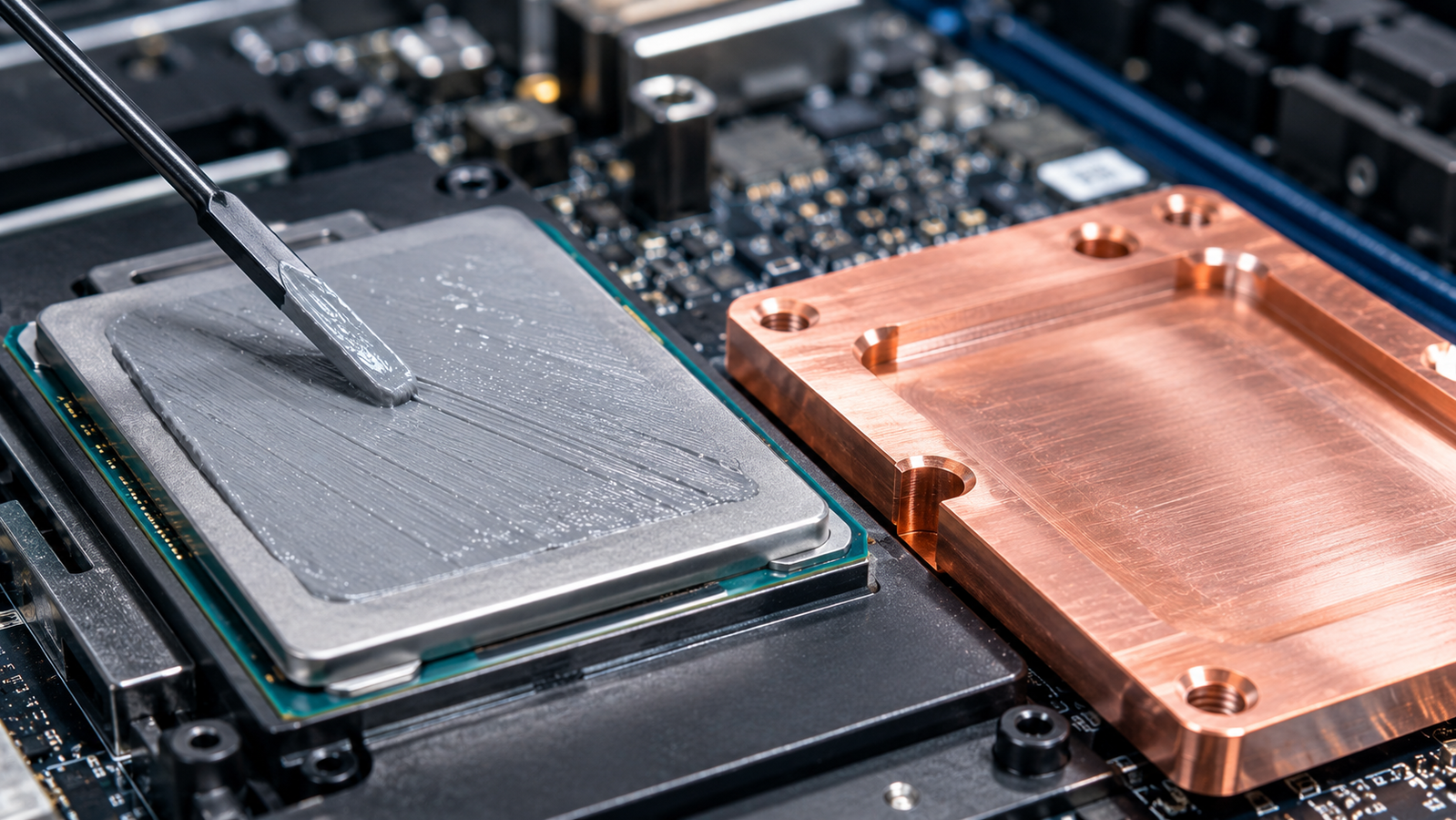
Follow the watts from junction to coolant — die, TIM1, spreader, TIM2, cold plate, convective film — and tally each layer’s resistance. The die is thin and crystalline; the spreader, per the spreader analysis, is high-conductivity metal or better; the convective film, once liquid, is strong. The interfaces are where the arithmetic sags. This is not a manufacturing defect to be tightened away; it is physics. Two engineering surfaces touch only at asperity peaks — the real contact area is a small fraction of the apparent area — and heat crossing the joint must either squeeze through those spots or traverse whatever fills the gaps2. A TIM exists to fill the gaps with something better than air. It never fills them perfectly, and the imperfection has a name.
Anatomy of an interface: BLT, bulk k, and two contacts
The total resistance of a TIM joint decomposes into three terms:
Rjoint = BLT / (kbulk·A) + (R″c1 + R″c2) / A
— the bond-line thickness divided by bulk conductivity and area, plus an area-specific contact resistance R″c (units of m²·K/W) at each face where the TIM meets a solid, divided by the joint area1. The datasheet advertises kbulk. Two distinct physical layers hide inside those contact terms and deserve separate names. Macroscopic thermal contact resistance arises from real contact area, voids, roughness, wetting and pressure — classical constriction physics2. Interfacial thermal boundary resistance arises at the atomic scale from phonon and electron transmission across dissimilar materials, with a research literature of its own3. Both can be present at once; the “contact term” a thickness-series measurement extracts is the effective macroscopic sum for the whole assembled interface, not the atomic-scale Kapitza resistance alone. And in thin, well-filled joints, these contact terms can dominate. The consequence is a design trap with a precise shape: when contacts dominate, improving bulk conductivity attacks the minority term. A tenfold-better filler in the same chemistry can move the joint by a disappointing sliver, while a wetting or pressure change that halves the contacts transforms it.
Watch where the kelvins go
The tool below builds a 1 kW junction-to-coolant stack and lets you attack it from both ends: raise the TIM’s bulk conductivity tenfold, or engineer the contacts instead, and compare what the stack does.
The lesson generalizes: before spending on a better material, find out which term you are fighting. That is a measurement question, and it has a standard — with fine print.
What ASTM D5470 measures — and what it cannot
The workhorse standard for TIM characterization is ASTM D5470: a steady heat flow is driven through the specimen clamped between two instrumented metal bars, temperatures are extrapolated to the two faces, and the joint’s total thermal resistance is computed at a known pressure and thickness4. Run at several bond-line thicknesses — with pressure, surface finish, cure state, temperature and preparation held closely consistent across the series — the data can be fitted to estimate an apparent bulk conductivity from the slope and the combined contact contribution from the intercept. Used this way, D5470 is exactly the instrument the design trap above demands. The fine print is equally important. The measurement is taken at the tester’s surface finish, pressure and temperature — not your lid’s; a standard day-one run does not capture service aging unless preconditioning and post-aging remeasurement are built into the protocol. A single-thickness measurement cannot independently separate bulk from contact contributions; unless another validated model is applied, the defensible output of such a run is the total thermal impedance of the joint at the tested conditions — and it should be reported as exactly that.
Thermal impedance vs thermal conductivity
The two quantities on a TIM datasheet answer different questions, and the industry’s vocabulary keeps them apart for good reason. Area-normalized thermal impedance (m²·K/W) is what a specific joint does: it bundles bond line, both contacts and the tested pressure and temperature into one number — the number your stack experiences, valid at those conditions. Thermal conductivity (W·m−1·K−1) is a material property: it predicts how impedance changes with thickness, but says nothing about the contacts. The practical rules follow directly. Comparing products? Compare impedance at your pressure and a stated thickness. Modeling a stack across thicknesses? You need conductivity and the contact terms, separated by a thickness series. Reading a datasheet that offers one number without saying which? Ask — a conductivity presented where an impedance belongs can make the product appear more favorable by excluding contact contributions.
Day two: pump-out, dry-out and the numbers that drift
Every value discussed so far is a day-one number, and TIMs are not day-one materials. Greases under cyclic clamping pressure migrate out of the joint — pump-out — leaving starved regions whose resistance climbs silently; volatile components evaporate — dry-out — stiffening the film and opening micro-voids; phase-change materials depend on reflow history; gap pads relax; cure chemistries continue curing. The families differ mainly in which aging mechanism they trade for which convenience1. The metrological consequence is that a TIM qualification has a time axis: the honest data set is resistance versus thermal cycles and versus bake time, at representative pressure — not a single pristine measurement. The engineering consequence is gentler than it sounds: a slightly worse day-one joint can outperform a nominally superior one if it remains stable while the other degrades during service. Datasheets rarely volunteer the second curve; qualification protocols should demand it.
The exotic end of the market illustrates the same trade in sharper relief. Liquid-metal interfaces offer bulk conductivities above many filled polymers and can sharply reduce the bond-line term, while introducing new qualification requirements: gallium-based materials can rapidly alloy with and damage aluminum unless an effective barrier is used — documented directly, along with the barrier layers that mitigate it5 — their electrical conductivity creates a short-circuit hazard if material escapes the intended joint, and time-dependent interfacial reactions must be evaluated for the actual material pair and service condition. The stack equation does not care how glamorous the middle term is; it sums all three, over the whole service life.
A related trap is comparing bench numbers with in-system inferences as if they were the same measurement. In a live server, interface resistance is usually back-calculated from junction telemetry, estimated power and an assumed stack model — three quantities each carrying their own error — whereas D5470 measures one joint under instrumented, controlled conditions. When the two disagree, the discrepancy is diagnostic rather than scandalous: it points at contact pressure differing from the bench, at power maps differing from the estimate, or at an aging mechanism the day-one bench test never saw. Treating the bench value as a calibration anchor and the in-system inference as a drift monitor uses each number for what it actually is.
Effective versus intrinsic: reading TIM data like a metrologist
The vocabulary that keeps TIM claims honest is the split between intrinsic properties — what the material is, measured on the material alone — and effective properties — what a joint does, measured with its interfaces included. Both are legitimate; confusing them is how stacks get mis-budgeted. Filler-level intrinsic claims deserve particular care: graphene’s spectacular in-plane conductivity, for example, was established on suspended flakes by opto-thermal Raman6, yet a graphene-filled pad conducts through-thickness, across the filler’s weak direction and across every filler–matrix boundary — the composite inherits the interfaces, not the headline. The same logic runs through this whole cluster: spreaders are limited by their joints, and even the coolant loop’s advantage, quantified in the liquid-cooling companion, is spent partly against interface resistance before the fluid ever sees the heat.
A qualification protocol that survives contact with reality
A TIM qualification worth its file size contains six elements. (1) Total joint resistance at your pressure and temperature, D5470-style, because that is the number your stack experiences. (2) A thickness series so bulk and contact terms are separated by extrapolation rather than assumed. (3) The intrinsic properties of the cured or bulk material where the design model needs them — conductivity, and for transient behavior diffusivity and volumetric heat capacity, measured on the material by the method its geometry permits — the full geometry-to-method selection logic is mapped in the pillar guide. (4) Direction, if the TIM is filled with anything anisotropic — aligned fillers make “the” conductivity a vector. (5) A statement of uncertainty and conditions for every number, without which comparison across vendors is theater. (6) Post-aging remeasurement — the same joint after thermal cycling, power cycling and high-temperature bake (humidity where the application warrants), with inspection for pump-out and phase separation; the post-aging curve, not the pristine day-one point, is what better represents service-life behavior. If a coating or assembled interface is the suspect in your stack, contact our thermal testing team to evaluate whether it is suitable for a geometry-matched thermal resistance measurement; the full method-selection logic — which method answers each measurement need — is mapped in the pillar guide. The interface is where your temperature budget goes to die quietly. Measure it like it matters, because it does.
Keep Exploring the ACS Thermal Metrology Knowledge Hub
This article is one chapter of the ACS thermal metrology knowledge hub. To keep going:
- Thermal conductivity & diffusivity testing: the pillar guide — methods, samples and a buyer’s framework in one place.
- Diamond and diamond–copper spreaders — from lab curiosity to chip-level hardware.
- Liquid vs air cooling in AI data centers — where each wins, and the measurements behind the choice.
- Validating a heat-spreader claim — turning datasheet numbers into buying discipline.
- Thermal testing services — send us the sample; get defensible numbers back.