
The migration of AI data centers from air to liquid is often narrated as an industry trend. It is better understood as a surrender to arithmetic. Every single-phase cooling loop, from a desktop fan to an immersion tank, obeys the same sensible-heat balance — Q = ρ·V̇·cp·ΔT — and the term that decides the contest is volumetric heat capacity, ρcp: roughly 1.2 kJ·m−3·K−1 for air against roughly 4,170 for water, so that at equal heat load and equal coolant temperature rise, water requires a roughly 3,500-fold lower volumetric flow than air — a fluid-property ratio that no fan design, duct layout or airflow engineering can alter, though it speaks to transport capacity alone, not to heat-transfer area, pressure drop or pumping power1. Current guidance describes AI rack densities climbing from roughly 120 kW toward several hundred kilowatts and links loads at and above approximately 100 kW per rack with direct-to-chip liquid or hybrid architectures2. For the highest-density AI and HPC racks, liquid cooling is increasingly core infrastructure rather than an optional enhancement. This article does the arithmetic, compares the three liquid routes — and surfaces the material measurements each route quietly stands on.
- 1The 3,500× volumetric-flow disadvantage
- 2Do the arithmetic yourself
- 3Cold plates, immersion, two-phase: three ways to spend the advantage
- 4What two-phase changes in the arithmetic
- 5Forty-five years from lab demo to mandate
- 6The measurements a liquid loop quietly depends on
- 7Keep exploring the knowledge hub
The 3,500× volumetric-flow disadvantage
Cooling a rack is a transport problem: some mass of fluid must absorb the heat and physically carry it away, warming by no more than the allowed ΔT as it does. Rearranging the heat balance, the required volume flow is V̇ = Q / (ρcp·ΔT). For a 40 kW rack at a 12 °C air rise, that is already several cubic meters of air per second, moving through a cabinet the size of a wardrobe. Triple the load to today’s AI baseline and the airflow becomes an architectural feature; push toward the several-hundred-kilowatt densities now in planning2 and airflow and ducting requirements become impractical for many high-density designs. Water at the same load and the same ΔT asks for a flow thousands of times smaller by volume — on the order of a hundred-plus liters per minute for an AI-class rack, industrial rack-scale piping and manifold flow rather than architecture. The volumetric-flow comparison strongly favors liquids as rack density rises; air merely enjoyed a long era of loads low enough to hide the handicap. And the fluid’s advantage is only half the story: at the package surface the attainable local heat-transfer coefficient can increase by one or more orders of magnitude when moving from forced air to a well-designed liquid interface, which is precisely the band structure quantified in the thermal-wall companion.
Do the arithmetic yourself
The tool below runs the balance live for air, water and a representative single-phase dielectric fluid. Set the load and the temperature rise you can spend; compare what each medium demands.
Note what the dielectric column shows: immersion fluids give up some of water’s ρcp to buy electrical safety — a reminder that coolant selection is a materials-property trade, with numbers that deserve verification rather than faith.
Cold plates, immersion, two-phase: three ways to spend the advantage
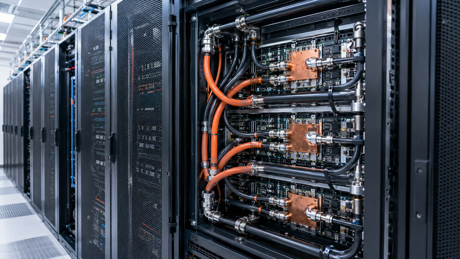
Direct-to-chip cold plates pipe the liquid to a metal plate clamped onto each high-power package, keeping fluid and electronics separated by a wall. They are a major route in the industry’s current liquid transition2, and their performance concentrates in three places: the plate’s internal channel design, the plate material’s conductivity, and — unavoidably — the interface between plate and package, which imports every issue analyzed in the TIM article. Single-phase immersion removes the cold-plate boundary: the electronics live in a dielectric bath and a much larger fraction of the external hardware surface becomes wetted area. It does not, however, eliminate the internal package interfaces — die attach, underfill, lid and molding compound still stand between the junction and the fluid — while fluid chemistry, compatibility and long-term stability become the engineering surface. Two-phase approaches — boiling at the hot surfaces or engineered phase-change loops — add latent heat to the arithmetic, multiplying the heat absorbed per unit of fluid; the deployed diamond/copper hardware discussed in the spreader article runs in exactly such a megawatt-class immersion phase-change cabinet3. The ranking among the three is application-dependent; what is common is that each route relocates, rather than abolishes, the materials problem.
What two-phase changes in the arithmetic
Everything above is sensible heat — fluid warms, fluid leaves. Phase change adds a second account: latent heat. When a fluid boils, each kilogram absorbs its enthalpy of vaporization, which over a modest coolant-temperature rise can substantially exceed the sensible heat the same kilogram could absorb by warming — so required mass flow drops again over a useful operating range. The temperature picture improves too, with a crucial caveat: the boiling wall does not sit at saturation but above it, by a superheat that depends on local heat flux, surface condition, nucleation behavior, pressure, flow regime and vapor quality — and beyond the critical heat flux, or in dryout, the heat-transfer coefficient can collapse and wall temperature can rise sharply. Within a stable envelope, phase change can moderate coolant-temperature rise and system-level gradients when flow distribution and boiling remain well behaved; that is the architecture of the megawatt-class phase-change immersion cabinet in which the deployed diamond/copper hardware runs3. The costs are real: saturation temperature must be engineered via fluid choice and pressure, condensers, vapor management, pressure control and associated balance-of-system equipment add capital complexity and parasitic energy of their own.
There is also a facility-level dividend. Liquid loops can carry large heat loads at much smaller volumetric flow rates and can operate with relatively warm supply and return temperatures, leaving heat in a form that is easier to reject through economizers or to reuse. Guidance frameworks for AI-era facilities treat cooling-energy efficiency and heat-recovery readiness as design criteria alongside raw capacity2; the same ρcp advantage that rescues the rack also can support lower facility cooling energy when paired with warm-water operation, efficient pumping, economization or heat recovery.
Forty-five years from lab demo to mandate
None of this physics is new. In 1981, Tuckerman and Pease demonstrated water-cooled microchannels etched into silicon removing 790 W/cm²4 — a flux comfortably beyond today’s package averages, achieved when the hottest commercial chips dissipated single-digit watts. Modern embedded-cooling research has extended the same lineage by co-fabricating microfluidics with the devices themselves5. What changed in the intervening decades was not the physics but the economics: liquid carries capital cost, leak risk, facility redesign and operational complexity, and for forty years loads were low enough that air’s simplicity won the trade. The AI rack ended the truce. When the arithmetic of the previous sections stops closing, the complexity premium of liquid becomes cheaper than the alternative — which is not cooling the computer.
The measurements a liquid loop quietly depends on
Liquid’s advantage is a property claim, and properties drift. Facility loops commonly use treated water or water–glycol mixtures rather than idealized pure water: glycol fractions shift its density, specific heat and viscosity in ways that directly resize the transport arithmetic above; corrosion inhibitors deplete; particulates and biological growth can foul surfaces, increase flow resistance and alter the effective heat-transfer performance assumed by the design. Dielectric immersion fluids age in their own ways — moisture uptake, dissolved air, gradual chemical change under thermal cycling — and their thermophysical properties on year three are an empirical question, not a datasheet lookup. A loop commissioned against nominal properties and operated against drifted ones runs a silent, growing gap between its design margin and its real one.
A liquid-cooling architecture is, in other words, a stack of material claims, each of them measurable. The coolant itself is specified by density, specific heat, viscosity and thermal conductivity — and for dielectric fluids, blends and aging fluids the datasheet values deserve periodic verification, since the loop’s entire transport capacity scales with ρcp. Standardized methods exist for exactly this: for aqueous and non-aqueous engine coolants and related fluids within its scope, ASTM D7896 provides a transient-hot-wire route to thermal conductivity, diffusivity and volumetric heat capacity — other dielectric immersion liquids require a validated transient-hot-wire or equivalent method demonstrated for that fluid class — and DSC determination of specific heat follows ASTM E12696,7; immersion fluids additionally warrant electrical resistivity, dielectric strength, moisture uptake, material compatibility and oxidation/aging monitoring, since those properties gate the whole architecture. The cold plate and manifold materials carry conductivity claims — copper alloys, brazed joints, and increasingly additively manufactured plates whose conductivity should be verified against the processing route, porosity and post-treatment condition rather than assumed from wrought-copper data, and therefore merits lot-level verification. The interfaces between plate and package remain the budget’s soft spot, with the qualification protocol laid out in the TIM companion. And the high-conductivity spreaders feeding heat to the plates carry the condition-tagged claims ranked in the materials-race article. Each material claim requires an appropriate measurement — some thermophysical, others electrical, chemical or compatibility tests — and each is matched to a specimen geometry (fluid, plate, film or bulk); that matching is the core of our thermal testing services, with the full method map in the pillar guide. At the highest rack densities, the transport arithmetic is pushing the industry toward liquid and hybrid cooling. Whether a particular loop delivers its arithmetic is decided by the properties of its materials — measured, not assumed.
Keep Exploring the ACS Thermal Metrology Knowledge Hub
This article is one chapter of the ACS thermal metrology knowledge hub. To keep going:
- Thermal conductivity & diffusivity testing: the pillar guide — methods, samples and a buyer’s framework in one place.
- Why AI chips hit the thermal wall — the heat-flux problem behind the packaging race.
- Thermal interface material testing — what actually limits the stack.
- Thermal testing services — send us the sample; get defensible numbers back.