
Once you understand how a dielectric barrier discharge works, the practical question becomes an engineering one: which reactor shape should you actually use? The geometry is not a cosmetic choice — it decides where the field concentrates, how gas flows through the discharge, how the cell loads the power supply, and ultimately which samples and processes it suits. This is a selection and design guide: it compares the main DBD reactor geometries — planar, coaxial, surface, and packed-bed — on the variables that drive a real choice, and maps each to the ACS Material reactor built for it. For the underlying discharge physics — microdischarge formation, Lissajous power, and streamer dynamics — see our companion article on DBD reactor physics and power supplies.
How to choose, in one paragraph: pick planar for flat samples, films, and surface activation; coaxial for continuous gas processing such as ozone and gas conversion, where residence time matters; surface discharge for treating exposed surfaces and thin layers; and packed-bed for plasma catalysis, where pellets sit in the discharge. All keep the plasma non-thermal by the same mechanism, so the decision is driven not by "cold versus hot" but by sample form, gas handling, electrical load, cleaning, and scale-up — the variables this guide compares.
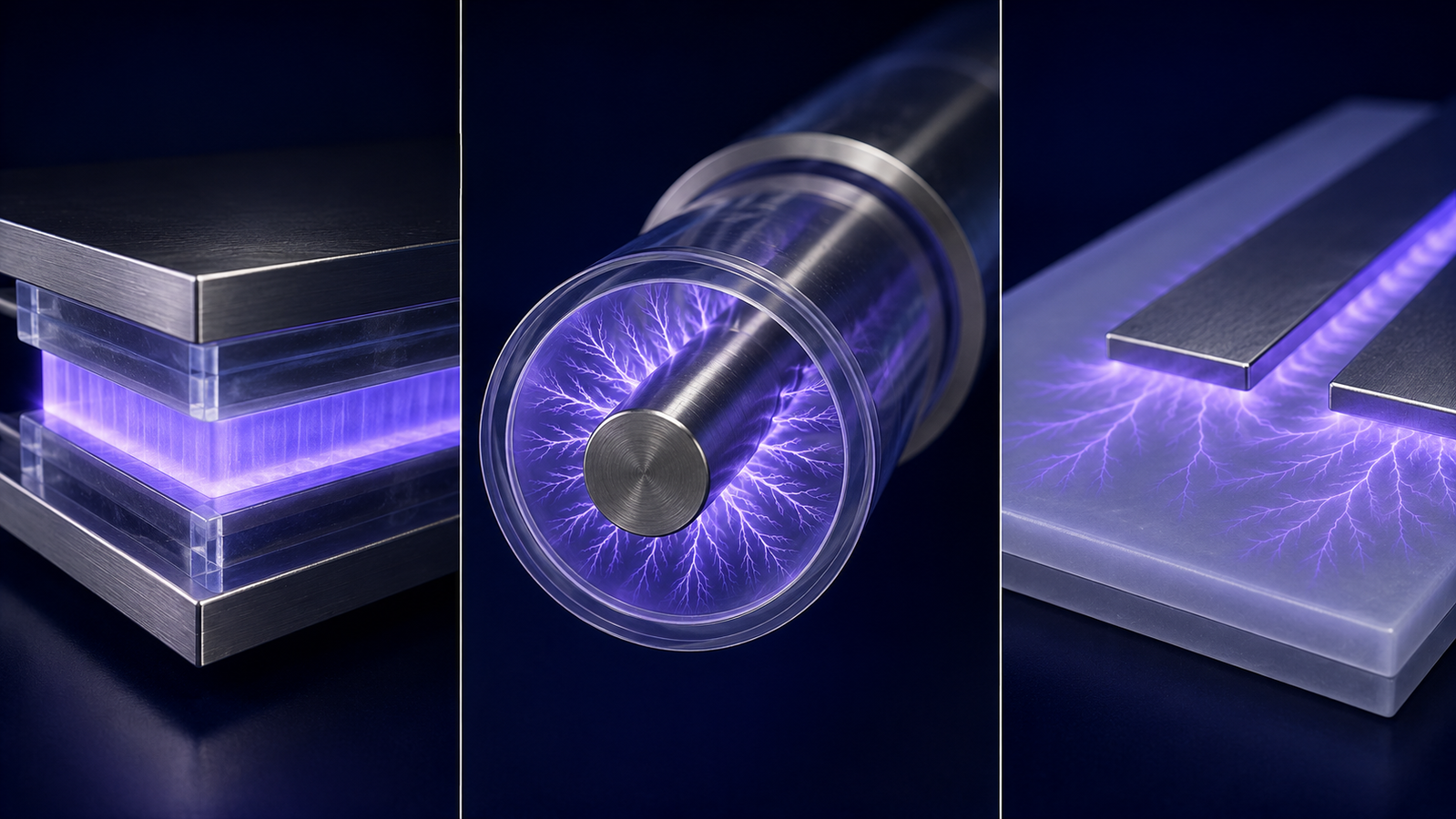
1. Why geometry matters in a DBD
Every dielectric barrier discharge works the same way at heart: an AC or pulsed high voltage breaks the gas down into a swarm of nanosecond micro-discharges, and charge accumulating on the dielectric snuffs each one out before it can heat into an arc, keeping the plasma non-thermal.1,2,3 That mechanism is geometry-independent — but almost everything else about a reactor depends on how the electrodes, dielectric, and gas gap are arranged.
Three things change with geometry. First, the field distribution: a flat gap gives a uniform field, a cylindrical gap concentrates it toward the inner conductor, and a surface arrangement produces intense fields at electrode edges that decay with distance.4 Second, gas handling: some geometries are natural flow-through reactors while others suit static or slow-moving gas. Third, what part of the world the discharge actually touches — a bulk gas volume, a flowing stream, or a solid surface. Numerical studies of the three basic arrangements show that although the underlying discharge dynamics are shared, the field structure and where the plasma forms differ substantially between them.5
One property is shared across every geometry and worth stating early: a DBD is fundamentally a capacitive device. The dielectric in series with the gap means the reactor presents a capacitance to its power supply, and the discharge power actually delivered is classically read from the charge–voltage Lissajous figure — a technique dating to Manley's 1943 analysis of the ozonizer discharge and still the standard today.6,7 This is why geometry and power supply cannot be chosen independently: the cell's capacitance, set by its shape and dielectric, is exactly the load the supply must drive.
2. The three geometries, side by side
The simulator below lets you switch between the planar, coaxial, and surface arrangements. Watch how the electrode layout, the field tendency, and the location of the discharge change with each — the same physics, packaged three different ways.8
3. Planar (parallel-plate)
The planar DBD is the textbook geometry: two flat electrodes face each other across a uniform gas gap, with a dielectric covering one or both. Because the field is approximately uniform away from the electrode edges in an ideal planar cell, micro-discharges tend to distribute across the area, making this the natural choice for treating flat samples, films, textiles, and webs.9,10 It is also the easiest arrangement to model, to instrument, and to scale up in area — add electrode width and you add throughput without changing the essential physics.
Under the right gas, electrode, and drive conditions a planar gap can even be pushed from the usual filamentary mode toward a more spatially uniform, diffuse discharge, which is prized for even surface treatment.8 For laboratory work — surface activation studies, film treatment, plasma-chemistry experiments — the planar cell is where most people start.11 ACS Material's dielectric barrier discharge experiment device is a planar cell of exactly this kind, and its reaction-kettle variant adapts the same principle to a sealed vessel for treating gases and liquids in a controlled volume.
4. Coaxial (cylindrical)
The coaxial DBD wraps the geometry into a tube. A center rod or wire sits inside a dielectric tube, with the outer electrode around the outside; gas flows through the annular gap along the tube axis. This shape has two defining features. First, the field is radial and stronger near the inner conductor — a direct consequence of cylindrical geometry — which shapes where breakdown initiates.4 Second, and more important in practice, gas passes continuously through the discharge, making the coaxial cell a natural flow-through reactor.1
That flow-through character is why coaxial and tubular DBDs are so widely used where gas must be processed in a stream rather than a batch: ozone generation, and plasma-driven gas conversion such as CO2 splitting and methane reforming.12,13 The residence time of gas in the discharge, set by the gap and flow rate, becomes a key process variable. ACS Material's dielectric barrier coaxial reactor is built for exactly this flow-through work, pairing with a CTP-2000K power supply to drive continuous gas processing.
The tubular idea relates to some atmospheric-pressure plasma jets, where a dielectric-tube arrangement lets the discharge blow out of a nozzle as a plume that treats surfaces outside the electrode region.14 Some jet devices, such as research-grade kINPen-style sources, share annular or tube-based electrode features — though atmospheric-pressure plasma jets span many other electrode configurations too.15 Where a coaxial reactor keeps the gas inside the tube, a jet lets it escape — two points on the same cylindrical-geometry family.
5. Surface (coplanar) discharge
The surface DBD breaks the usual picture: rather than crossing a uniform gap to an opposing electrode, the discharge propagates primarily along the dielectric surface. Electrodes sit on one face of a dielectric, with a counter-electrode on the reverse side, so the plasma spreads laterally from each electrode edge, most intense at the edge and decaying with distance.4 The field is highly non-uniform, concentrated where the surface electrode meets the dielectric.
This makes surface discharges ideal wherever the target is a surface or a thin layer just above it rather than a bulk gas volume. Two families of use stand out. In aerodynamics, surface DBD actuators create a wall-hugging plasma and an associated body force that can control airflow over a wing or blade — a well-developed field with its own extensive literature.16 And for surface sterilization and thin-layer treatment, the discharge acts directly on whatever sits on the dielectric, delivering reactive species right at the surface.17,18,19
Surface discharges are also demanding to diagnose precisely because the plasma is thin and clings to the dielectric: the highly collisional, near-surface region complicates almost every measurement, from optical temperature estimates to probe methods.20 When such discharges contact liquids — as in water treatment and biomedical work — a whole additional layer of plasma–liquid chemistry comes into play.21
6. Packed-bed: where geometry meets catalysis
A powerful variation fills the gap of a DBD — usually a coaxial or planar one — with dielectric or catalyst pellets, creating a packed-bed reactor. This is not merely a fourth shape; it is where reactor geometry and chemistry meet. The pellets polarize in the applied field, and the contact points between beads, and between beads and the wall, become sites of intense local field enhancement that concentrate the plasma exactly where a catalyst surface sits.22
The payoff is plasma catalysis: energetic electrons activate stable molecules while the catalyst steers them toward desired products, all at near-ambient bulk temperature.23,24 Packed-bed DBDs are central to plasma-driven CO2 conversion, dry reforming of methane, and nitrogen fixation, and the bead size and dielectric constant become design variables in their own right.25,26 The bead-scale field enhancement they exploit is the same physics that makes contact points matter in any packed DBD.12
The reach of these geometries is broad. Beyond gas conversion, DBD reactors in their various shapes underpin cold-plasma treatment of food and agricultural products, where a low gas temperature protects heat-sensitive material,27 and plasma medicine, where cold surface and jet discharges act on tissue.28,29 In every case the geometry is chosen to put the non-thermal discharge where the process needs it.
7. Choosing a geometry
The choice follows directly from what you are treating and how the gas must move — a mapping that reflects how the low-temperature plasma field has organized these arrangements over decades of development.30 A quick guide:
| Geometry | Field profile | Gas handling | Best for | ACS Material reactor |
|---|---|---|---|---|
| Planar | Approx. uniform (mid-gap) | Batch / static / slow flow | Flat samples, films, textiles, surface activation | DBD experiment device; reaction kettle |
| Coaxial | Radial, stronger near rod | Continuous flow-through | Ozone, CO2/CH4 conversion, gas processing | DBD coaxial reactor |
| Surface | Intense at edges, decays with depth | Open volume above surface | Aerodynamics, surface sterilization, thin layers | (surface-electrode cells) |
| Packed-bed | Enhanced at bead contacts | Flow-through with catalyst | Plasma catalysis, gas conversion | Coaxial or kettle cell with packing |
That maps each geometry to a product. The deeper engineering decision turns on how each shape handles your sample, your gas, and the electrical load — the variables that actually separate a good fit from a poor one:
| Design variable | Planar | Coaxial | Surface DBD | Packed-bed |
|---|---|---|---|---|
| Best sample form | Flat substrate | Flowing gas | Exposed surface | Gas + catalyst |
| Active region | Inter-electrode area | Annular volume | Dielectric surface | Pellet voids |
| Residence-time control | Limited | Strong | Not primary | Strong |
| Load behavior | Capacitive | Capacitive / flow-dependent | Surface-distributed | Strongly nonlinear |
| Cleaning & maintenance | Easy | Moderate | Easy | More difficult |
| Scale-up method | Increase area | Number-up / length | Increase surface | Number-up / bed volume |
Which geometry should I choose? As a quick rule of thumb: flat-material surface treatment → planar; continuous gas conversion or ozone → coaxial; large or open exposed surfaces → surface DBD; plasma catalysis with a packed catalyst → packed-bed. Sample form and gas handling usually decide it; electrical load, cleaning, and scale-up then refine the choice.
Whatever the geometry, the discharge cell is only half the system — it must be driven by a power supply matched to its capacitance, gap, and target power. For how the two work together, and how to choose the supply, see our plasma processing guide and the deeper DBD reactor physics companion. Send us your gas, flow, and process target and we will match the cell and supply.
Knowledge hub
- Plasma Processing Guide — the pillar overview of plasma, discharges, applications, and power supplies.
- DBD Reactors: Physics & Power — the underlying discharge physics behind these geometries.
- Plasma Frequency, Duty Cycle & Waveform — how the supply drives whichever cell you choose, and the load it sees.
- DBD Experiment Device — a planar parallel-plate cell for surface and film work.
- DBD Coaxial Reactor — a tube-in-tube flow-through reactor for ozone and gas conversion.
- DBD Reaction Kettle — a sealed-vessel variant for gas, gas–solid, gas–liquid, and liquid treatment.
FAQ
What is the difference between planar and coaxial DBD reactors?
A planar DBD has flat parallel electrodes and an approximately uniform field (away from the edges), best for treating flat samples in batch. A coaxial DBD is a tube-in-tube design with a radial field and continuous gas flow through the annular gap, best for ozone and gas conversion where throughput matters.
Why are coaxial DBDs so widely used for ozone generation?
Because they are natural flow-through reactors: gas passes continuously through the annular discharge along the tube, so a stream can be processed steadily. Coaxial and tubular configurations are widely used in ozone generation and gas conversion, where continuous throughput matters more than batch treatment.
What is a surface (coplanar) DBD used for?
The discharge spreads across a dielectric surface rather than bridging a gap, so it treats whatever sits on or just above that surface. Common uses are aerodynamic flow control with surface DBD actuators, surface sterilization, and thin-layer processing.
What is a packed-bed DBD reactor?
A DBD whose gap is filled with dielectric or catalyst pellets. The pellets polarize in the field and create intense local field enhancement at their contact points, concentrating the plasma at catalyst surfaces — the basis of plasma catalysis for gas conversion.
Does geometry change whether the plasma is thermal or cold?
Geometry alone does not determine it — a DBD stays non-thermal chiefly because the dielectric self-limits each micro-discharge before it becomes a hot arc. But geometry is not irrelevant: it influences electric-field concentration, current density, power density, heat removal, and arc stability, so it is one of several factors — along with gas, pressure, voltage, waveform, and cooling — that together shape gas heating and the discharge regime.
Can one power supply drive different reactor geometries?
Often yes, within the supply's voltage, frequency, and power window. What matters is the electrical load each cell presents — its capacitance and gap. The CTP-2000K family, for example, pairs with planar, coaxial, and kettle cells; the reactor is chosen for the process, the supply for the load.