Ask what graphene conducts and you will get a spectacular number; ask in which direction and the conversation becomes engineering. Within its atomic planes, graphene is among the best heat conductors ever measured; in stacked graphene, graphite-like films and flake assemblies, transport across the layers is orders of magnitude weaker, throttled by weak interlayer coupling. That single fact organizes everything useful about graphene in thermal management — why films of it spread hotspot heat sideways so effectively, why fibers spun from it can channel heat along a line, why composites built from it can disappoint, and why it is not an automatic thermal-interface material despite the headline conductivity. This article walks the product forms honestly — strengths, limits and the measurements that separate them.
One material, two conductivities
In-plane, graphene’s heat is carried by phonons riding some of the stiffest bonds in nature; landmark measurements on suspended single layers reported values in the vicinity of 4,800–5,300 W·m−1·K−1 at room temperature1 — several times copper, in a sheet one atom thick. Through-plane is another world: between stacked layers only weak van der Waals forces couple the lattices, and transport collapses accordingly. This is not a defect to be processed away; it is the material’s structure speaking. Direct measurements on graphene-based micrometer-thick films — the same physical specimen probed in both directions — resolve the intrinsic anisotropy ratio quantitatively2, and every engineering decision below is downstream of that ratio. Writing one scalar conductivity for graphene into a thermal model risks a material-model error unless isotropy — or a direction-specific effective-property approximation — has been explicitly justified — if that approximation is unjustified, the resulting model error will usually surface in the transport direction most important to the application.
The physics of the split is worth one paragraph, because it predicts how processing moves the numbers. In-plane transport rides long-wavelength acoustic phonons whose mean free paths in clean lattices are extraordinary; anything that scatters them — grain boundaries between flakes, lattice defects, residual functional groups from the oxide route, wrinkles and folds — taxes the in-plane value first, which is why flake size, alignment and graphitization temperature are the levers that separate an ordinary film from an exceptional one. Through-plane transport, by contrast, was never carried by strong bonds at all: phonons must hop across van der Waals gaps, so intrinsic layer-normal transport remains weak — although architecture and vertical alignment can substantially raise the effective through-plane transport of an assembled structure. The asymmetry of the levers is the practical point — production choices move the strong direction across a wide range while the weak direction stays weak, so the anisotropy ratio is a useful processing-sensitive signature, and measuring both directions on the same specimen reads it directly.
Films: lateral heat spreaders
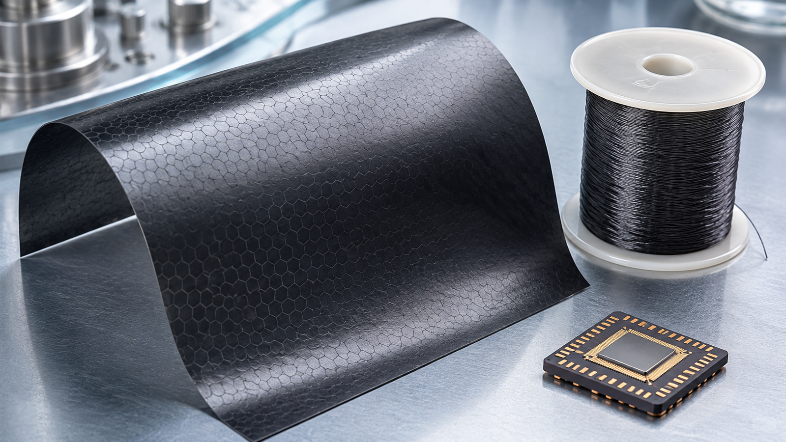
The form that turns anisotropy into a product is the graphene film: micrometers-thick assemblies of aligned flakes, most commonly built from graphene oxide and then thermally or chemically restored, whose in-plane conductivity can be engineered to very high values through flake size, alignment, defect repair and densification — a production-and-property landscape mapped in a dedicated review3. Deployed flat against a hotspot, such a film does exactly what its structure prefers: it moves heat sideways, diluting a concentrated source over a larger footprint before the heat crosses into whatever sits beneath. That lateral-spreading role — in portable electronics and increasingly explored for higher-power contexts — is where reported application results concentrate3. The through-plane limitation is least damaging here, but it never disappears: the heat must still cross the film’s two interfaces and its finite thickness on the way out, so system performance depends on both the lateral conductance and the downstream interface stack. Supported and substrate-integrated graphene tells a subtler story: conductivity measured on large CVD layers depends on layer number and substrate interaction4, a reminder that “graphene’s conductivity” is always a statement about a specific structure in a specific environment. Our Graphene Series supplies the material forms this ecosystem builds on, from graphene oxide to CVD films.
How the in-plane number itself is established deserves a sentence, because the film’s geometry constrains the metrology. Free-standing strips are native territory for suspended transient electro-thermal measurement; films on substrates invite the 3ω route with its fabricated heater line5 or time-domain thermoreflectance, whose sensitivity to thin layers is set by modulation frequency, transducer and the multilayer model6; and the modern record of suspended-sample electro-thermal measurement runs from millimeter fibers down to atomic-thickness two-dimensional films7. Different methods answer subtly different questions about the same film — which is exactly why a quoted value without its method is an incomplete sentence.
Fibers: heat along a line
Spin graphene flakes into a continuous fiber and the anisotropy story goes one-dimensional. Wet-spinning from liquid-crystalline graphene oxide dispersions produces continuous fibers and yarns8, a route demonstrated early alongside other facile fabrication approaches9; with high-temperature treatment and structural ordering, graphene fibers have reached simultaneously high thermal conductivity and mechanical strength10 — heat and load carried along the same aligned axis. The measurement story matters as much as the fabrication story here: a fiber is precisely the free-standing one-dimensional geometry that transient electro-thermal methods were built for, and TET characterization of wet-spun graphene fiber resolves its axial transport directly11 — no substrate, no deposited heater, the fiber itself as sensor. For genuinely one-dimensional thermal roles — routing heat along a flexible path, or exploring thermally active textiles and cables — the fiber is the honest graphene format.
Composites and aerogels: interfaces rule
Blend graphene into a matrix and intuition says the composite inherits the filler’s conductivity. Reality is governed by interfaces: every flake boundary, flake–matrix junction and void adds thermal resistance in series with the spectacular intrinsic transport, and the network’s connectivity — not the filler’s headline value — sets the outcome. The extreme case makes the principle vivid: graphene aerogels exhibit extremely low effective thermal conductivity — their measured behavior reflects the combined effect of tiny solid fraction, extreme porosity, tortuous conduction paths and large sheet-to-sheet contact resistance, with interface thermal resistance identified as the dominant transport bottleneck12 — the same chemistry that tops conductivity charts, architected into an insulator. The lesson generalizes beyond graphene: in aligned carbon-nanotube bundles, engineering the inter-tube contacts produced a nineteen-fold increase in bundle conductivity with the constituent tubes unchanged — the network, not the filler, was the variable that mattered13. And the interface knob turns both ways: laser photoreduction of graphene aerogel microfibers retunes their electrical and thermal behavior dynamically, interfaces being edited in place14. Between the aligned film and the aerogel lies the whole composite design space, and position within it is set by loading, alignment, interfacial engineering and processing. The practical consequence is the one this series keeps returning to: composite conductivity is a measured property of a specific formulation and lot, not a calculated inheritance from the filler datasheet.
Why graphene is not automatically a TIM
The thermal-interface role is where graphene’s reputation and its structure most often collide. A TIM’s job is overwhelmingly through-plane: carry heat across a thin gap between two solid faces, and couple intimately to both. Flake-aligned graphene structures bring their weak direction to exactly that task, and the joint’s performance is then set by through-plane transport plus two contact resistances — the full anatomy we dissect in the TIM testing companion. None of this makes graphene useless at interfaces; it makes orientation the entire game — vertically aligned architectures, through-plane-engineered assemblies and hybrid formulations exist precisely to point the strong axis across the gap, and their worth is decided by measured through-plane resistance under realistic pressure, not by the in-plane number on the headline. The honest summary: flake-aligned graphene films naturally favor lateral spreading over through-plane gap filling; making a gap-filler out of graphene is a deliberate engineering act — one of the architectures above — that must be verified as such.
What does that engineering act look like in practice? Three families recur. Vertically aligned architectures grow or assemble the strong axis across the gap, buying through-plane transport at the price of a harder, less conformable interface that then leans on the contact terms. Hybrid formulations disperse graphene into compliant matrices, where the composite lesson of the previous section governs: percolation and interfacial coupling, not filler purity, decide the outcome. And thermally augmented pads laminate spreading layers with compliant ones, splitting the lateral and through-gap jobs between materials that are each doing what they prefer. Every one of these is legitimate; none of them inherits the in-plane headline for free; and all of them are adjudicated the same way — measured joint resistance, at application pressure, before and after representative aging.
| Form | Strong direction | Best role | Main limitation | Measurement fit |
|---|---|---|---|---|
| Film | In-plane | Lateral heat spreader | Through-plane path and interfaces | TET (free-standing), 3ω/TDTR (supported) |
| Fiber | Axial | Linear heat routing | Junctions, diameter limits | TET |
| Composite | Network-dependent | Shapeable conductive part | Filler–matrix interfaces | Geometry-specific |
| Interface material | Through-plane (engineered) | Gap filling | Orientation, contact terms | Joint resistance (D5470-type) |
Measure the direction you use
Every section above lands on the same closing discipline. Graphene’s value in a thermal design is directional, so its verification must be directional: in-plane diffusivity for a spreader film, axial transport for a fiber, through-plane resistance under pressure for an interface role — each on specimens from the lot in hand, by a method matched to the geometry, with contacts isolated and uncertainty stated. That is the general verification protocol of our claim-validation guide, applied to one of the most anisotropic material families in the catalog. Free-standing films and fibers are native territory for transient electro-thermal measurement — the method behind our TET guide and our thermal testing services — and the broader method-selection logic lives in the pillar guide. Choose the form whose strong direction matches your heat path, then measure that direction: that is the whole art of using graphene well.
Keep Exploring the ACS Thermal Metrology Knowledge Hub
This article is one chapter of the ACS thermal metrology knowledge hub. To keep going:
- Thermal conductivity & diffusivity testing: the pillar guide — methods, samples and a buyer’s framework in one place.
- Validating a heat-spreader claim — turning datasheet numbers into buying discipline.
- The high-conductivity materials race — diamond, TaN and the leaderboard, read like a metrologist.
- Differential TET for 2D materials — supported-sheet transport down to atomic thickness.
- Graphene Series materials — the material family these articles measure.
References
This article discusses graphene films, fibers and composites for thermal management in general terms. Reported conductivity values are specimen-, direction- and condition-specific as cited; product-grade materials require lot-level verification as described. Consult product datasheets and SDS for the specific Graphene Series materials referenced. The interactive simulator is a schematic teaching tool for anisotropic heat spreading, not a substitute for measurement.