
Every in-situ diffraction result begins with a decision made before the beam is ever switched on: which attachment goes on the diffractometer. A heating stage, a cryostat, a vacuum chamber, a flow cell — the piece of hardware that holds the sample is not an accessory to the experiment, it is the experiment. It sets the temperature the sample can reach, the atmosphere it sits in, the angular range the detector can see, and the fraction of the signal that survives the trip through windows and domes. This guide is a practical tour of the non-ambient attachment: the three axes every design trades against, how heating stages differ from cryostats and vacuum chambers, why sample height quietly governs data quality, and how to match an attachment to the diffractometer you actually own.
What the attachment decides: three variables set almost every attachment apart — the temperature range it can impose, the atmosphere it can hold around the sample, and the diffraction geometry it preserves through its windows. A resistive furnace and a liquid-nitrogen cryostat sit at opposite ends of the first axis; an open-air hot stage and a sealed vacuum chamber at opposite ends of the second; a wide-arc Kapton window and a small beryllium dome differ on the third. No single attachment wins all three, so the right choice is the one whose compromises match your material and your instrument — and, running underneath all of it, sample height and thermal drift decide whether the numbers you extract are trustworthy.
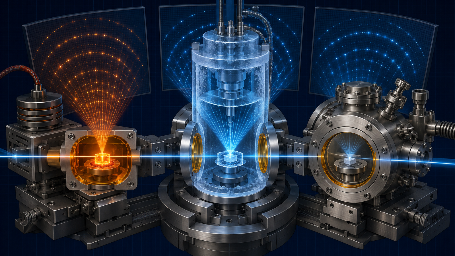
1. The attachment is the experiment
The instinct is to think of the diffractometer as the instrument and the stage as a bolt-on. For non-ambient work the priority is reversed. The diffractometer supplies X-rays and records where they scatter; everything that makes the experiment in-situ — the temperature, the gas, the timed sequence of states — is imposed by the attachment. The history of the field is in large part a history of attachment design: the earliest dynamic diffraction experiments were built around custom heated cells, because commercial holders simply could not do the job.1 Watching a solid crystallise, react, or transform in real time only became routine once the hardware to hold it under non-ambient conditions matured.2 Time-resolved diffraction of solid-state reactions, in particular, depends entirely on a sample environment that can drive the reaction while the beam watches.3
That dependence is worth stating plainly because it reframes the buying decision. When you choose an attachment you are choosing the boundaries of the experiment: the hottest phase transition you can reach, the most reactive gas you can flow, the fastest process you can follow, and — through the window and geometry — the weakest reflection you can still measure. A study of energy-storage electrodes, a catalyst under working gas, a mineral dehydrating on heating: each imposes different demands on the stage, and the review literature on real-time diffraction returns again and again to the sample environment as the thing that enables or limits the science.4
2. Three axes: temperature, atmosphere, geometry
Strip away the model numbers and every non-ambient attachment is a set of choices along three axes. Temperature range is the most obvious: does the sample need to reach 1500°C, or drop to −190°C, and how fast must it move between setpoints? Atmosphere is the second: air, inert gas, a reactive mixture, or vacuum — each demanding different seals, windows, and chamber materials. Geometry is the third and least discussed: whether the attachment works in reflection or transmission, and how much of the diffraction cone its windows let the detector see. The three are not independent — a wide temperature range forces material choices that constrain the atmosphere, and a sealed atmosphere forces a window that limits geometry — which is exactly why no attachment optimizes all three at once.
Underneath these three sits the constant that laboratory diffraction is built on: the focusing geometry. Many conventional laboratory diffractometers use Bragg–Brentano reflection geometry, where a flat sample sits at the center of the goniometer circle and the divergent beam re-focuses at the detector only if the sample surface is exactly on that circle — though parallel-beam, transmission (capillary), grazing-incidence, and area-detector geometries are also common.5 Every attachment has to preserve that condition while heating, cooling, or enclosing the sample — and the degree to which it succeeds is the quiet difference between a stage that gives clean, interpretable data and one that does not. The interactive explorer below maps the first two axes; the third runs through the rest of the guide.
The five families below map onto those axes. The table is a quick orientation, not a spec sheet — the real limits of any attachment depend on its exact model, geometry, atmosphere, sample, and manufacturer.
| Attachment family | Representative range | Environment | Common geometry | Best suited for | Main limitation |
|---|---|---|---|---|---|
| Peltier stage | Mild cooling to moderate heating | Air / vacuum | Reflection | Convenient routine variable-temperature work | Limited high-temperature ceiling |
| LN2 stage | Cryogenic to several hundred °C | Atmosphere / vacuum | Reflection / transmission | Broad heating-and-cooling range | LN2 supply and condensation control |
| Closed-cycle cryostat | Near 10 K to moderate temperatures | Vacuum / He exchange gas | Varies | Deep-cryogenic diffraction | Cost, vibration, cooling time |
| Resistive furnace | RT to about 1000–1200 °C | Air / inert / vacuum | Reflection / transmission | High-temperature phase evolution | Window, gradient, sample-height control |
| Radiant / IR furnace | Very high temperature | Controlled chamber | Beamline-oriented | Melting and solidification | Specialized geometry and calibration |
Representative ranges only; final limits depend on the specific attachment, geometry, atmosphere, sample, and manufacturer.
3. XRD heating stages and furnace attachments
Heating is the workhorse of non-ambient diffraction, and heating attachments divide by how they deliver the heat. The most common laboratory design is the resistive strip or block heater: the sample sits on or in a heated element, and conduction brings it to temperature. In suitable furnace designs these commonly cover several hundred degrees up to roughly 1000–1200 °C with good stability, and their compact construction keeps the sample close to the goniometer center; higher-temperature work generally calls for specialized heater materials or radiant designs.6 A well-built heating stage controls not just peak temperature but the thermal path to the sample, because the number a controller reports and the temperature the diffracting volume actually reaches can differ — a gap that has to be calibrated, not assumed.
For the highest temperatures, radiant designs take over. Focused-lamp and mirror furnaces concentrate infrared radiation onto a small sample, and because radiant power scales as the fourth power of absolute temperature, these reach regimes — well above 1500°C — where resistive elements struggle.7 The trade is a steeper thermal gradient across the sample and a more demanding optical alignment. Between the extremes sit multipurpose stages designed to work across a wide span and, importantly, in more than one diffraction geometry: a single attachment that heats plate-like samples to over 1170 K while allowing measurement across the full orientation space, for instance, has to manage sample displacement from thermal expansion and the effect of its own protective dome on the beam.8 Those two effects — height change and dome scattering — are the recurring costs of heating, and we return to the first of them in section 6.
4. XRD cryostats: LN2 and closed-cycle cooling
Cooling is the mirror image of heating, and it splits into two technologies. Liquid-nitrogen (LN2) cryostats are the everyday choice: a cold stream or a cooled block brings the sample down to roughly −190°C, enough for the great majority of low-temperature phase transitions; cooling also reduces atomic thermal motion and thermal diffuse scattering, which can increase the intensity and visibility of weak Bragg reflections. Cooling is also how the unusual lattice behaviour of certain materials — negative thermal expansion, where the cell contracts on heating — is measured cleanly against a low-temperature baseline.9 Closed-cycle refrigerators reach much lower — a two-stage helium engine can hold a sample below 10 K — and do so without consuming cryogen, at the cost of a bulkier cold head that must be decoupled from the goniometer. A classic closed-cycle design for powder work pairs the cold engine with a spinning sample holder in an open helium-exchange-gas atmosphere for thermal contact, while keeping a wide open interval of diffraction angles — a reminder that cooling attachments face the same geometry constraints as heaters.10
Cooling brings one problem heating does not: condensation and icing. A sample held below the dew point will collect frost from any moisture in the chamber, burying the pattern under ice peaks and a diffuse background. The fix is to purge the sample space with dry gas or evacuate it, which is why cooling attachments are almost always also atmosphere-controlled — the cryostat and the vacuum or inert-gas system are two functions of one enclosure. This coupling is the practical reason low-temperature diffraction and controlled-atmosphere diffraction are rarely separate purchases. Cooling rate itself can matter to the result: in materials such as potassium nitrate, the phase reached on cooling depends on how fast the sample is taken down, which only a stage with controlled, reproducible cooling can capture faithfully.11
5. Vacuum XRD chambers and controlled-atmosphere cells
The third family controls what surrounds the sample. The motivations are distinct. Vacuum protects an oxidation-sensitive sample at high temperature and removes air scatter that would otherwise add background; it also removes convective heat transfer, though its net effect on temperature uniformity depends on the heater design, sample mounting, and conductive and radiative heat paths, so sample temperature should be validated under the actual configuration. Inert gas — nitrogen or argon — can protect many oxidation-sensitive samples while generally posing less volatilization risk than vacuum, though gas flow rate, sample vapor pressure, and exhaust conditions still matter. Reactive atmosphere is the most demanding: flowing a real working gas over the sample while diffracting is what turns a heating experiment into a study of chemistry, and it is central to catalysis and oxidation work, where the active phase exists only under the reaction conditions.12
Delivering these atmospheres well is a hardware discipline of its own. A large-volume, atmosphere-controlled diffraction furnace was purpose-built to give a defined gas environment across a wide temperature range for exactly this kind of study,13 and compact reaction cells that mount directly on a standard goniometer head brought portable temperature-plus-atmosphere control to a wide range of instruments.14 At the demanding end, in-situ studies of catalyst oxidation and reduction rely on flowing controlled gas mixtures through the cell while the diffraction runs, so the phase evolution is followed under genuinely working conditions rather than reconstructed afterward.15 Even solid-state device chemistry — the formation and degradation of thin-film materials — is now followed by diffraction under controlled atmosphere and temperature together.16 A special case worth naming is humidity control: for hydrates, clays, and pharmaceutical solids, an environmental chamber that regulates relative humidity and temperature simultaneously lets diffraction track how the structure responds to water uptake and loss.17 Across all of these, the same rule holds — the atmosphere the sample experiences is the one the cell can actually seal and deliver, not the one nominally set, so validation matters.18
6. Sample height & defocus: the quiet error
Here is the failure mode that catches everyone. In Bragg–Brentano geometry the flat sample must sit exactly on the focusing circle; if its surface is displaced even slightly — toward or away from the beam — every peak shifts in angle and the pattern defocuses. This sample-displacement error is one of the largest systematic errors in laboratory powder diffraction, and it is easy to mistake for real structural change.19 In a non-ambient attachment the danger is acute, because heating expands the stage and the sample, physically moving the surface during the run: a peak that drifts as the temperature climbs may be reporting thermal expansion of the lattice, thermal expansion of the holder, or both, and separating them takes care. The multipurpose heating-stage literature treats sample displacement from thermal expansion as a first-order design concern for precisely this reason.8
The defense is calibration against a standard. A certified reference material such as NIST SRM 660c lanthanum hexaboride provides well-characterized line positions and line shapes for modelling the instrument profile; measurements taken in the actual sample-holder geometry can then be used to evaluate zero-shift and sample-displacement effects, so that genuine sample behaviour is separated from geometric artifacts.20 Two further points complete the picture. First, an observed peak width is never purely the sample’s: it is the sample’s broadening convolved with the instrument’s own profile, which must be measured on a strain-free, large-crystallite standard and removed before size or strain is extracted.19 Second, quantitative work — whether the phase fractions in a mixture are right, whether the numbers from a heated run mean anything — ultimately rests on whole-pattern Rietveld refinement of a properly aligned, properly calibrated pattern, not on reading raw peak heights.21 A well-designed attachment earns its keep by holding the sample where the geometry needs it, run after run, so these corrections stay small and stable; parametric refinement across a whole temperature series then extracts the trend directly.22 A concrete illustration: in-situ high-temperature diffraction of glass-ceramic crystallization can follow the number density, size, and lattice parameters of a growing phase quantitatively through a heating run — but only when displacement and profile are under control.23
7. Windows, in one paragraph
Something has to contain the hot zone, the cold zone, or the vacuum while staying nearly invisible to X-rays, and that job falls to the window. The materials are low in atomic number so they transmit hard X-rays with little absorption and add little scattering of their own — polymer films such as polyimide (Kapton) for moderate conditions, beryllium or graphite domes for higher temperatures and better structural integrity, and thin single-crystal or amorphous materials where a clean background matters. Window fabrication is a real constraint: achieving high X-ray transmission over a usefully wide angular aperture drove the development of polyimide windows in the first place, and the choice of window ultimately bounds the angular range and the weakest reflection a given attachment can measure.24 The geometry consequences of windows and 2θ coverage are a study in their own right and are treated in our dedicated guide on windows and diffraction geometry.
8. Matching the attachment to your diffractometer
Five questions before choosing a non-ambient XRD attachment
Those five questions map directly onto the three axes, worked in a fixed order.
Choosing well comes down to matching the three axes to your instrument and your science, in a fixed order. First, temperature range. A phase transition at 300°C, a decomposition at 1400°C, and a cryogenic ordering transition each point to a different family — a moderate resistive heater, a high-temperature furnace, or a cryostat — and nothing else matters until this is settled. Second, atmosphere. Air is fine for a stable oxide; an air-sensitive or oxidation-prone sample needs inert gas or vacuum; a catalyst needs a real reactive-gas flow cell. Third, geometry and detector. Your diffractometer’s configuration — reflection or transmission, point or area detector — determines which attachments physically fit and how fast you can collect. A position-sensitive or area detector captures a broad angular range in parallel and can greatly shorten acquisition; whether a single exposure covers the full diffraction pattern depends on detector size, detector distance, X-ray energy, geometry, and the required angular range.25 The photon-counting detectors that make this possible — recording a wide swath of the pattern at once with low noise — are what turned many laboratory in-situ runs from slow scans into practical experiments.26
For X-ray diffraction specifically, ACS Material’s InSitu Pro™ line provides attachments across all three axes. The anchor for diffraction is the dedicated AXCH600 / AXCH400V XRD heating-and-cooling stages, a family of two heating-and-cooling variants that pair a resistive heater with liquid-nitrogen cooling behind a shared Kapton arc window (2θ 0°–164°): the AXCH600 operates from −190°C to 600°C in atmosphere, while the AXCH400V operates from −190°C to 400°C in vacuum — between them spanning two of the three axes. For the hottest work, the AXH1200 ultra-high-temperature XRD stage pushes the temperature axis higher, and for beamline experiments the AIH1600-SR synchrotron IR furnace brings radiant heating to the highest regimes. To narrow the choice against a specific temperature program and diffractometer, the stage selection guide walks the decision step by step, and the interactive stage selector filters the whole range by temperature, atmosphere, and geometry.
Knowledge hub
- In-Situ XRD: Watching Crystal Structure Evolve — the companion guide on what the diffraction pattern actually tells you as structure changes.
- In-Situ Heating, Cooling & Electrical Stages: A Theory Guide — the pillar overview of the whole in-situ stage family and the physics behind it.
- XRD Stage AXCH600 / AXCH400V — the dedicated heating-and-cooling XRD stage for laboratory diffractometers.
- InSitu Pro™ Stage Selection Guide — the five-step framework for matching a stage to your instrument, temperature range, and atmosphere.
- InSitu Pro™ Stage Selector — interactively filter the whole range by application, temperature, cooling method, chamber, and probes.
FAQ
What is a non-ambient XRD attachment?
It is a sample stage that replaces the standard holder on a diffractometer and imposes a controlled condition — a defined temperature, gas atmosphere, or vacuum — on the sample while keeping the X-ray beam free to reach it and return to the detector. Heating stages, cryostats, and controlled-atmosphere or vacuum chambers are the three main families, and many real attachments combine two of these functions in one enclosure.
What is the difference between a heating stage and a furnace attachment?
The distinction is how the heat is delivered. A resistive heating stage brings the sample to temperature by conduction from a heated strip or block and is compact and stable into the low-thousands of degrees Celsius. A radiant furnace — focused lamps or mirrors — delivers heat by infrared radiation and reaches much higher temperatures, at the cost of steeper thermal gradients and more demanding alignment. Which you need is set by the peak temperature and the uniformity your sample requires.
Do I need vacuum, or is inert gas enough?
It depends on why you are controlling the atmosphere. Inert gas (nitrogen or argon) is enough to protect most air- or oxidation-sensitive samples and is simpler to run. Vacuum goes further: it also removes air scatter from the background and removes convective heat transfer, though its effect on temperature uniformity depends on the heater, sample mounting, and heat paths, and it can pull volatile components out of some samples. If you need to flow a specific reactive gas — for catalysis or oxidation studies — neither vacuum nor static inert gas will do; you need a flow cell.
Why do my peaks shift when I heat the sample, even without a phase change?
Two effects overlap. The lattice itself expands on heating, which genuinely shifts peaks — that is real thermal expansion. But heating also expands the stage and moves the sample surface off the focusing circle, which shifts peaks through a purely geometric sample-displacement error. Separating the two requires calibrating the displacement against a certified standard and, ideally, refining the whole pattern rather than tracking a single peak position. A well-designed attachment minimizes the geometric part through stable mounting, controlled sample positioning, height adjustment, or calibration-and-correction workflows — whether by active compensation or a validated setup routine depends on the model.
Can one attachment do both heating and cooling?
Yes — combined heating-and-cooling stages are common, and they are efficient when your work spans both sides of room temperature. Combined stages are available, though their upper-temperature and atmosphere limits can differ by model: in the InSitu Pro™ line the AXCH600 covers −190°C to 600°C in atmosphere, while the companion AXCH400V covers −190°C to 400°C in vacuum. For temperatures far above that, or far below −190°C, you move to a dedicated high-temperature furnace or a closed-cycle cryostat respectively, because no single technology spans the entire range.
How do I know which attachment fits my diffractometer?
Work the three axes in order — temperature range first, then atmosphere, then geometry and detector — and then check physical and electronic compatibility with your specific instrument (reflection or transmission, point or area detector, mounting and control interface). The InSitu Pro™ stage selection guide and interactive selector are built to do exactly this narrowing; for an unusual configuration, the ACS Material team can confirm fit against your instrument and temperature program.
References
This article is provided by ACS Material LLC for educational purposes and describes non-ambient X-ray diffraction attachments — heating stages, cryostats, and controlled-atmosphere or vacuum chambers. Temperature ranges, atmospheres, and geometric specifications cited refer to representative designs and the specific studies referenced; the actual range, uniformity, window aperture, and compatibility of a given attachment depend on the model, options, sample mounting, and diffractometer. The temperature a sample reaches can differ from the controller setpoint, and sample temperature and displacement should be validated with a certified standard under the actual experimental conditions. The interactive simulator is a schematic teaching tool — the category coverage bands are illustrative of the temperature and atmosphere regimes each attachment family typically serves, not specifications of any particular product, and not predictive software. Consult product datasheets and specifications for the exact capabilities of each stage.