
A rotor stator homogenizer mixes by spinning a rotor at high speed inside a close-fitting stationary stator, so that the liquid is forced through a narrow gap and out through openings in the stator. Rotor–stator mixers are used for emulsification and for dispersing solid particles into liquids [1][2]. This guide explains the spec-sheet terms tip speed and shear rate, where those numbers stop being useful, and how to choose a dispersing tool by volume, vessel and job. It ends with the three ALab™ homogenizers, described only in ACS Material's own words and values. For how homogenizing compares with stirring, vortexing and shaking, see our guide to laboratory mixing methods.
Quick answer: Tip speed is the speed of the rotor's outer edge, v = πDN, where D is the rotor diameter and N the rotational speed in revolutions per second. Dividing tip speed by the rotor–stator gap gives a nominal shear rate. The literature quotes typical tip speeds of 10–50 m/s, gaps of 100–3000 µm and nominal gap shear rates of 20,000–100,000 s⁻¹ [1][4]. Those figures describe the head, not the result. Much of the literature attributes breakup mainly to turbulence, jets and impact near the stator openings rather than to simple gap shear, and the result also depends on how often the liquid passes through the head [1][2]. Choose the dispersing tool first by working volume and job, and plan to monitor and control sample temperature while you run it.
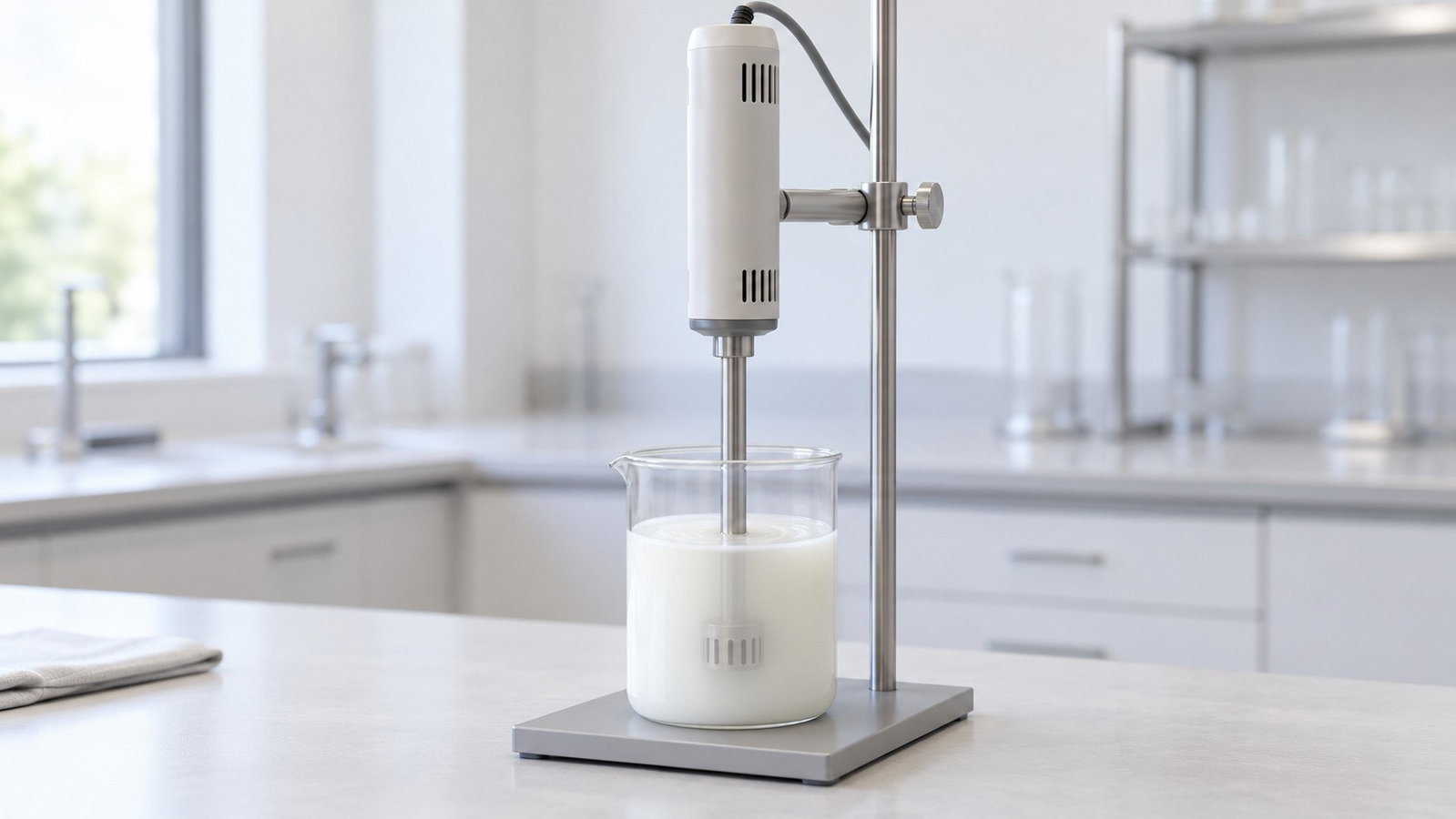
1. How a Rotor Stator Homogenizer Works
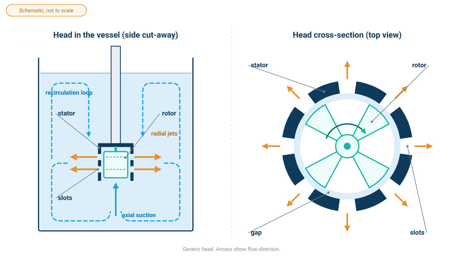
A rotor–stator head has two parts: a rotor that turns at high speed and a stator that stays still around it. Their typical feature, as one study of a laboratory mixer puts it, is "a narrow gap between the rotor and the stator" [1]. A practical guide to sample disruption describes the classic laboratory version as an outer stationary tube with slots and an inner turning shaft with slots, and adds: "This design is essentially the same as an electric razor" [5].
When the rotor turns, it draws liquid into the head and throws it outward against the stator. In the laboratory mixer studied by Pacek, Baker and Utomo, each jet forms when liquid hits the leading edge of a stator hole, which "converts tangential velocity into radial velocity" [1]. The jets travel out into the vessel, the liquid circulates, and it is drawn back into the head. A batch rotor–stator therefore works in two places at once: an intense zone in and around the head, and a gentler circulation that brings the rest of the batch back to that zone [1][2].
Colloid mills, toothed devices and axial- and radial-discharge rotor–stator mixers are all grouped as high-shear mixers [1]. Laboratory testing is almost always done in batch mode, with the head dipped into a vessel, while inline versions pump the liquid through the head [2]. Typical uses are "to blend miscible liquids of different viscosities, to disperse fine solid particles in viscous liquids and to form stable emulsions of immiscible liquids" [1].
The ALab™ homogenizers. Of the three ALab™ homogenizers, only the D-500 is described with a rotor and stator: "The motor drives the rotor at high speed, and the sample is homogenized or dispersed in the gap between the rotor and the stator, usually in a short period of time." The D-160 is described with interchangeable dispersing shafts, and the D-200 with blade sets; for the D-200, ACS Material says: "Its internal suction structure homogenizes and emulsifies immiscible liquids at high speed." This article does not assign a head geometry to the D-160 or the D-200.
2. Homogenizer Tip Speed: What It Is and How to Read It
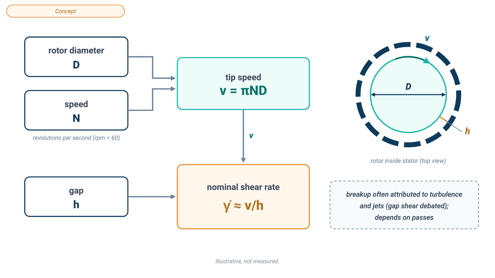
Tip speed is the speed at which the outer edge of the rotor moves. For a rotor of diameter D turning at N revolutions per second:
v = π × D × N
Rotor speed in rpm is divided by 60 to give N. Håkansson's review, for example, defines the Reynolds number of a batch rotor–stator "based on the rotor tip-speed" [2].
A literature example (not an ALab™ specification). Padron's dissertation used a batch laboratory rotor–stator mixer whose rotor had "a diameter of 28 mm", with a gap of 0.2 mm between the rotor blade tips and the stator [3]. He ran it at "low rotor speeds (2000 – 3000 rpm)" and at "higher speeds (4000 – 7000 rpm)" [3]. Taking 5000 rpm from that range, N = 83.3 rev/s, so v = π × 0.028 m × 83.3 s⁻¹ ≈ 7.3 m/s. This is an illustration of the formula with literature geometry only.
Two practical points follow from the formula:
- The same rpm gives different tip speeds on different heads. Tip speed scales with rotor diameter, so a larger rotor at the same rpm moves faster at its edge. A higher maximum rpm on a spec sheet does not, on its own, mean a higher tip speed.
- Tip speed is not the whole story. Turbulent power draw scales as N³D⁵ (Section 4), so heads with equal tip speed can put in very different energy [1][2].
What ACS Material lists. None of the three specifications uses the term "tip speed". The D-500 gives its speed as "Max. linear velocity" and the D-160 as "max. circumferential speed". The D-500 has one range for the instrument, "Max. linear velocity 22.7–36 m/s". It does not assign any part of that range to a particular dispersing head or speed level, so read it only as the full range specified for the instrument. The D-160 has a value for each dispersing shaft (Table 1). No linear velocity or tip speed is specified for the D-200, and none is calculated here.
Table 1. Speed, volume and viscosity of the ALab™ homogenizers
| Model (product type) | Speed range | Speed figure (as specified) | Volume | Max. viscosity (separate rating) |
|---|---|---|---|---|
| D-500 (High-shear homogenizer) | 10000–30000 rpm | Max. linear velocity: 22.7–36 m/s (one range specified for the instrument) | Listed heads: 1–50 mL (DS-500/5); 10–5000 mL (DS-500/1, DS-500/2) | 10000 mPa·s |
| D-160 (Handheld homogenizer) | 8000–32000 rpm | Per shaft — DS-160/5: "max. circumferential speed 6.3 m/s"; DS-160/7: "max. circumferential speed 10 m/s"; DS-160/10: "max. circumferential speed 14 m/s" | 0.1–50 mL (DS-160/5); 1–150 mL (DS-160/7); 1–250 mL (DS-160/10) | 5000 mPa·s |
| D-200 (Benchtop digital display homogenizing emulsifier) | 2000–20000 rpm | — | 20–1200 mL | 5000 mPa·s |
Source: ACS Material product specifications (October 2026). A dash means the specification is not listed. The D-500 range is specified for the instrument and is not assigned to a head or speed level. D-500 volumes are the listed dispersing heads only. Volume and maximum viscosity are separate ratings, not a combination reached at the same time. No rotor diameter, gap width or shear rate is specified.
3. Shear Rate: The Nominal Number and Its Limits
The shear rate most often quoted for a rotor–stator is a nominal value for the gap: tip speed divided by gap width,
γ̇ (nominal) ≈ v ÷ h
where h is the rotor–stator gap. It assumes simple shear between a moving and a fixed wall. Table 2 gives the published working window.
Table 2. Literature ranges for rotor–stator mixers (not ALab™ specifications)
| Quantity | Literature value | Source |
|---|---|---|
| Rotor–stator gap width | 100–3000 µm | [1], citing Karbstein & Schubert 1995; also [4] |
| Typical rotor tip speed | 10–50 m/s | [1], citing Atiemo-Obeng & Calabrese 2004; also [4] |
| Nominal gap shear rate | 20,000–100,000 s⁻¹ | [1], citing Atiemo-Obeng & Calabrese 2004; also [4] |
| Example: batch laboratory head | rotor 28 mm, gap 0.2 mm | [3] |
| Example: batch laboratory head | stator 28.2 mm, gap 0.175 mm | [1] |
| Example: inline head | gap 0.24 mm; 3000–12000 rpm | [4] |
Literature values for laboratory and industrial rotor–stator mixers, quoted from the cited papers. They are not specifications of any ACS Material product; no ALab™ gap width or shear rate is specified.
Continuing the literature example from Section 2 (28 mm rotor, 0.2 mm gap, 5000 rpm), the nominal gap shear rate is 7.3 m/s ÷ 0.0002 m ≈ 37,000 s⁻¹ [3], inside the literature window but still only nominal.
Why "nominal" matters. Several findings show that gap shear is a poor predictor of what happens to a sample:
- A simulation of an inline mixer showed that "the shear in the gap was not a simple shear, but turbulent shear flow" (Calabrese et al. 2002, as summarised in [1]).
- In a slotted-head mixer, narrowing the gap, which raises the nominal shear rate, led to larger average drops (Calabrese et al. 2000, as summarised in [1]).
- Calabrese et al. (2002) still concluded that a narrow gap is needed for efficient dispersion, "even if the shear in the gap is not a major contributor to the dispersion process" (as summarised in [1]).
- Not every study agrees on the mechanism: Myers et al. (1999) reported that drops and agglomerates are mainly broken by planar shear in the gap, while others attribute breakup to turbulent pressure fluctuations (both as summarised in [1]).
No ALab™ shear rate. For none of the three ALab™ homogenizers is a rotor–stator gap width or a shear rate specified. This article therefore gives no shear rate for any ALab™ model, and a specified speed figure should never be divided by a gap taken from the literature.
4. What Breaks Drops and Agglomerates: Energy, Jets and Passes
If gap shear is not the main mechanism, what is? Much of the literature points to the intense turbulence near the head, and to the jets leaving the stator openings and the liquid hitting the stator surfaces [1].
Energy is concentrated at the head. In a batch rotor–stator run in turbulent flow, the power drawn by the shaft follows P = NP ρ N³ D⁵, where NP is the power number and ρ the liquid density [2]. Håkansson reports batch rotor–stator power numbers often in the range 1–3, depending on the head and the tank [2]. That energy is concentrated: measurements in one laboratory mixer indicated that "70% of the energy is dissipated in close proximity to the mixer head" [1], and estimates for another design put about 80% of the total dissipation in the high-intensity region [2]. Because the energy dissipated there rises with the cube of rotor speed [1], a modest increase in rpm raises the energy input near the head sharply.
Passes through the head. In a batch vessel each parcel of liquid passes through the head many times. One model summarised by Håkansson relates the mode drop diameter to rotor speed with an exponent of −6/5, which matches turbulent breakup theory, and to the number of passes with an exponent of −1/5 [2]. In plain terms, drop size falls steeply with rotor speed and only slowly with extra processing time, and the time needed depends on how fast the vessel circulates through the head [2].
Same tip speed, different result. Taken together, these findings mean that equal tip speed does not give equal drop or agglomerate size across head sizes, stator designs or batch volumes. A larger batch circulates through the head less often, a different stator changes the power number, and viscosity and surfactants change how drops break [2][3]. Treat tip speed as a way to describe a head, not as a recipe for a result. No particle or drop size is specified for any ALab™ instrument.
5. Heat: Why Samples Warm Up and What to Do
In a batch rotor–stator, the shaft energy does not disappear. Håkansson states that under turbulent conditions "all of the shaft energy (except the losses …) must ultimately be dissipated as heat" [2]. Without sufficient heat removal, a sample can warm during a run. Padron found that at low speeds his mixer did not heat the tank, but at higher speeds "the heat generated was significant", and crushed ice was added to the surrounding bath to hold the temperature [3]. The sample-disruption guide notes that rotor-stators "can generate heat", and advises that if active proteins are needed, especially heat-labile ones, "processes which generate heat or cause foaming should be avoided" [5].
Practical steps (general laboratory practice, not instrument claims):
- Cool the vessel. Stand it in an ice or water bath for long runs or heat-sensitive samples [3].
- Run in bursts. Short runs with pauses let the bath remove heat between bursts.
- Measure. Check the sample temperature rather than assuming it.
- Keep the head immersed. A head near the surface draws in air and can make the sample foam, which the guide also advises avoiding for heat-labile proteins [5].
The ALab™ specifications. None of the three lists a sample temperature rise or a cooling accessory. The D-200 operating mode is specified as "Continuous operation for approx. 15 min"; how warm a sample becomes in that time is not specified. The D-500's automatic overload protection "protects the motor"; it does not control the sample temperature. Whichever instrument you use, plan for cooling.
6. Choosing a Dispersing Tool
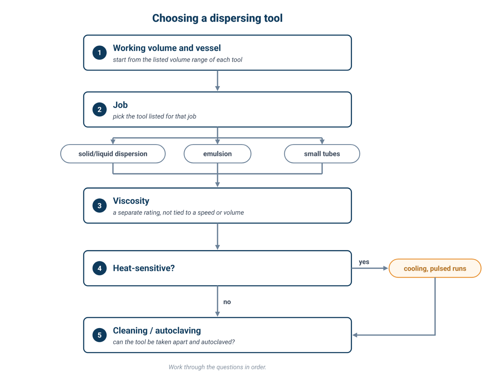
The dispersing tool (head, shaft or element, depending on the maker) matters as much as the motor. Work through these questions in order.
- Working volume and vessel. Use each listed volume range or processing capacity as the starting constraint, then check actual vessel geometry and tool immersion for your setup.
- The job. Dispersing a powder into a liquid, making an emulsion and homogenizing a soft solid sample are different jobs, and makers often list different heads for each.
- Viscosity. Instruments list a maximum viscosity. It is a separate rating; the speed, head or volume at which it applies is not specified.
- Heat sensitivity. Plan cooling and run time (Section 5).
- Cleaning. Shafts can be "difficult to clean", and fibrous material can catch inside the shaft assembly [5]. Check whether the tool can be taken apart and autoclaved.
How ACS Material organises the ALab™ tools. The choice is made by volume and by job, not by tip speed. For the D-160, ACS Material says: "Select the dispersing shaft for your working volume from the Dispersing shafts table." For the D-500: "Select the dispersing head from the Dispersing heads table," and lists each head by application. The D-200 has two blade sets listed by capacity. Table 3 lists the tools as ACS Material names them.
Table 3. ALab™ dispersing tools
| Dispersing tool | Instrument | Description |
|---|---|---|
| DS-160/5 dispersing shaft | D-160 | Volume 0.1–50 mL; max. circumferential speed 6.3 m/s. Dispersing tool for solid/liquid media; small amounts of solid/liquid mixtures. |
| DS-160/7 dispersing shaft | D-160 | Volume 1–150 mL; max. circumferential speed 10 m/s. Dispersing tool for solid/liquid media; small amounts of solid/liquid mixtures. |
| DS-160/10 dispersing shaft | D-160 | Volume 1–250 mL; max. circumferential speed 14 m/s. Dispersing tool for solid/liquid media; small amounts of solid/liquid mixtures. |
| DS-500/1 dispersing head | D-500 | Solid and liquid dispersion, general purpose. Volume 10–5000 mL. |
| DS-500/2 dispersing head | D-500 | Emulsion, general emulsion purpose. Volume 10–5000 mL. |
| DS-500/5 dispersing head | D-500 | Small amounts of solid and liquid dispersion. Volume 1–50 mL; for tissue homogenization, mixing and suspension in microcentrifuge tubes, tube strips and centrifuge tubes. |
| Blade set 1 (small capacity) | D-200 | Ø12 mm, length 15 cm; processing capacity 20–1000 mL |
| Blade set 2 (large capacity) | D-200 | Ø18 mm, length 16 cm; processing capacity 20–1200 mL |
Source: ACS Material product specifications (October 2026); D-500 head descriptions shortened to job and volume; ordering numbers omitted. Rotor diameters, gaps and shear rates are not specified for these tools. The D-200 blade-set diameter is the specified size for the blade set; no speed figure is derived from it.
For the D-500, ACS Material notes that other rotor/stator combinations are available on request. This article covers only the listed heads, so the D-500 volumes here stop at 5000 mL.
7. Three ALab™ Homogenizers, in ACS Material's Words
D-500 — high-shear homogenizer. The D-500 high-shear homogenizer is the only one of the three described as a rotor–stator. It lists a speed range of 10000–30000 rpm in 6 speed levels, 500 W power, and one instrument-level value, "Max. linear velocity 22.7–36 m/s"; no part of that range is assigned to a particular dispersing head. Its three listed dispersing heads cover 1–50 mL (DS-500/5) and 10–5000 mL (DS-500/1 and DS-500/2). "Replaceable rotors and stators share the same shaft, and the rotor can be dismounted, cleaned and sterilized." Rotor–stator processing can generate heat, so monitor sample temperature and cool as needed [2][3][5].
D-160 — handheld homogenizer. The D-160 handheld homogenizer is described as a "portable, lightweight homogenizer" with a speed range of 8000–32000 rpm in 10 levels and 160 W power. Its three dispersing shafts cover 0.1–50 mL, 1–150 mL and 1–250 mL, and each carries its own specified speed figure (Table 3). "The dispersing shafts are fully autoclavable and interchangeable for easy dismantling and cleaning." High-speed homogenizing can generate heat, so monitor heat-sensitive samples and cool as needed [3][5].
D-200 — benchtop homogenizing emulsifier. The D-200 benchtop homogenizing emulsifier has a speed range of 2000–20000 rpm, a 200 W motor and a processing volume of 20–1200 mL with two blade sets. "The speed is set with a knob (stepless) and shown on the digital display." Its operating mode is specified as "Continuous operation for approx. 15 min", and no tip speed is specified. High-speed homogenizing can generate heat, so monitor sample temperature and cool as needed [3][5].
8. Spec-Sheet Checklist
When comparing rotor–stator homogenizers, ask for:
- Rotor diameter and gap for each head. Rotor diameter is needed to calculate tip speed from rpm; gap width is needed to calculate nominal gap shear rate.
- Tip speed — is it specified, and for which head and speed? A single range for an instrument is not a per-head figure.
- Volume range per head, not only for the instrument.
- Maximum viscosity and the conditions it refers to.
- Operating time and any specified limit on continuous running.
- Cooling options and how the sample temperature will be monitored.
- Materials, dismantling and autoclaving of the wetted parts.
9. Frequently Asked Questions
What tip speed does a rotor stator homogenizer need?
There is no single figure. The literature describes typical rotor tip speeds of 10–50 m/s [1][4], but the result depends on head, batch volume, viscosity, formulation and run time [2]. Test on your own sample.
Is a higher rpm always better?
No. Higher speed raises energy input sharply, and with it heat and the risk of foaming [1][3][5]. Tip speed depends on rotor diameter as well as rpm, so rpm alone does not compare two tools.
How do I calculate the shear rate of my homogenizer?
The nominal gap shear rate is tip speed divided by the rotor–stator gap. You need the tip speed and gap width for your head; if tip speed is not specified, calculating it from rpm also requires rotor diameter. Treat the result as nominal; much of the literature attributes breakup to turbulence, pressure fluctuations and jets near the stator openings, while other studies emphasize gap shear [1][2].
Why does my sample get hot?
Nearly all the energy put in by the shaft ends up as heat in the batch [2]. Use a cooling bath, run in bursts and check the temperature [3][5].
Rotor–stator or ultrasonic probe?
They break up material in different ways and have different side effects. We compare them in our homogenizer vs sonicator guide.
Can one head cover everything from 1 mL to 5000 mL?
Not on the ALab™ D-500: ACS Material lists DS-500/5 for 1–50 mL and DS-500/1 and DS-500/2 for 10–5000 mL. Choose the head for your volume.
Choosing a rotor–stator for emulsions and dispersions? See the D-500 high-shear homogenizer and its listed dispersing heads.
10. Keep Exploring the Mixing Hub
- Laboratory mixing methods guide: every mixing method compared.
- Homogenizer vs sonication for dispersions: shear or ultrasound?
- Overhead stirrer vs magnetic stirrer: stirring viscous samples.