
Homogenizer vs sonicator is a common comparison when graphene nanoplatelets, carbon nanotubes (CNTs) or metal-oxide nanoparticles need to be dispersed in a liquid. A rotor–stator homogenizer works by intense mechanical shear and turbulence at a spinning head. Sonication works by cavitation, the growth and violent collapse of small bubbles driven by ultrasound. A stirrer keeps the whole liquid moving. This guide compares the three at device level first (mechanism, working volume, heat, noise and contamination) and then summarises what the published literature reports for graphene, CNTs and nanoparticles. There is no single winner: the right method depends on the material, the job and the batch. For the wider picture, see our guide to laboratory mixing methods.
Quick answer: Sonication puts very high local energy into a small volume; a probe delivers more of it than a bath [1]. A rotor–stator homogenizer concentrates energy at its head and circulates the batch through it, which suits larger or more viscous batches [2][3][4]. A stirrer wets, premixes and keeps a dispersion suspended; for low-viscosity CNT systems, the Couette-type stirring analysis in Huang and Terentjev found "very little hope of achieving dispersion" [5]. Both high-energy methods have side effects: sonication can shorten nanotubes and fragment flakes [6][7]; rotor–stator processing can generate heat [3], while turbulent high-shear processing with surfactants can entrain air and foam [8]. Test on your own material and measure the result.
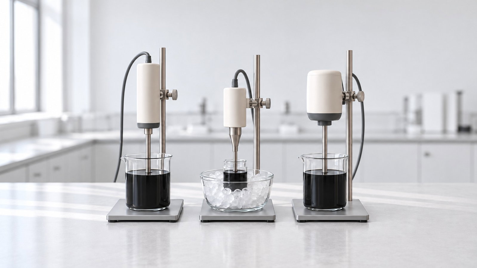
1. Homogenizer vs Sonicator vs Stirrer at a Glance
Rotor–stator homogenizing. A rotor turns at high speed inside a stationary stator, and the typical feature of the head is "a narrow gap between the rotor and the stator" [2]. Liquid is drawn into the head and thrown out through the stator openings as jets; at each opening the flow "converts tangential velocity into radial velocity" [2]. Most of the work is done in the intense zone at the head, and circulation brings the rest of the batch back to it [2][3]. Our rotor stator homogenizer guide explains tip speed, nominal shear rate and dispersing-tool choice; those definitions are not repeated here.
Sonication. Ultrasound in a liquid creates cavitation bubbles, and their collapse causes "an extremely high strain rate in the fluid in the proximate regions of bubble implosion", reported at up to 10⁹ s⁻¹ [5]. The energy reaches the sample either from a probe (horn) immersed in it, called direct sonication, or through the liquid of a bath and the wall of the sample container, called indirect sonication [1]. The cavities are not spread evenly; their distribution is "inhomogeneous throughout the solution" [5].
Stirring. A magnetic or overhead stirrer moves the whole batch at comparatively low shear. Huang and Terentjev estimated that stirring-type (Couette) shear mixing reaches strain rates of about 500–4,000 s⁻¹, and that in a low-viscosity solvent the stress reaching nanotube clusters is so small that it offers "very little hope of achieving dispersion" [5]. That estimate is for stirring geometries, not for rotor–stator heads. Stirring has a different job in a dispersion workflow (Section 7).
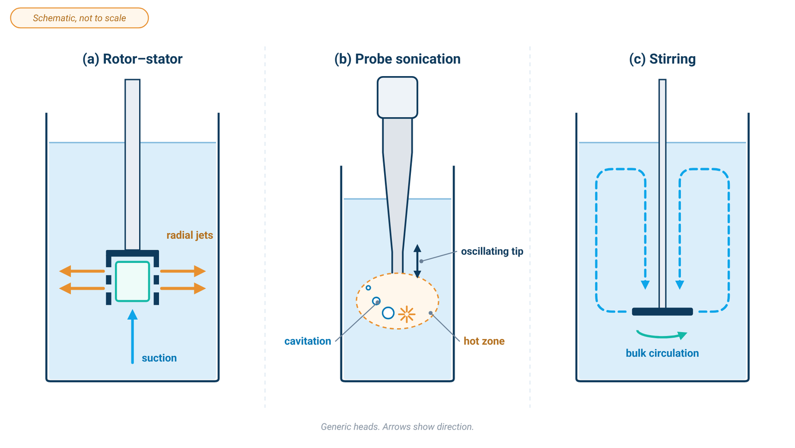
Table 1. Rotor–stator, probe, bath and stirring compared (literature and principle; no product values)
| Rotor–stator homogenizer | Probe sonication (direct) | Bath sonication (indirect) | Stirring | |
|---|---|---|---|---|
| Mechanism | Shear and turbulence at the head; jets through the stator openings [2] | Cavitation at the tip; local strain rates reported up to 10⁹ s⁻¹ [5] | Cavitation in the bath liquid; energy crosses the bath and the vial wall [1] | Bulk flow at low shear [5] |
| Energy delivery | Concentrated at the head; the batch circulates through it [2][3] | Higher effective energy into the sample than a bath [1]; thousands of W/L typical when exfoliating graphite [4] | Lower energy input; result depends on the bath, its fill level and the vial position [9] | Spread through the whole batch |
| Volume and scale | Head and batch size affect scale; Paton et al.'s laboratory shear-mixing setup operated at about 100 W/L [4] | Suits small volumes; scale-up is limited [4][9] | Several closed vials at once; less reproducible than a probe [9] | Large batches; suspends and premixes |
| Heat | Under turbulent conditions, shaft energy ultimately dissipates as heat [3]; cooling baths were used in laboratory studies [10] | Bulk heating from cavitation; ice bath and pulsed mode recommended [1] | Bath warms; cool it or exchange the water [9] | Not a focus of the sources used here |
| Noise | Not covered in the sources used here | Acoustic enclosure and hearing protection recommended [1] | Not covered in the sources used here | Not covered in the sources used here |
| Contamination | Wetted-part materials matter; wear particles are a general caveat | Tip erosion releases titanium particles into the sample [1] | No probe in the sample [1] | Stirring element touches the sample |
| Typical side effects | Heating [3]; foaming and air entrainment are reported in turbulent shear exfoliation with surfactants [8] | Nanotube shortening, flake fragmentation, local heating, foaming [1][6][7] | Slower; defects still build up with time [11] | Little breakup of CNT clusters in low-viscosity liquids in the cited stirring analysis [5] |
Literature and principle only, from the cited sources; none of them tested an ACS Material product. The numbers describe the cited studies, not any instrument sold by ACS Material.
Read Table 1 as a map of mechanisms, not a ranking. Each mechanism has a drawback on each side, and Section 6 lists the damage modes in full.
What ACS Material lists. Table 2 gives the specifications of the three ALab™ homogenizers. It is kept separate from Table 1 on purpose: no gap width, shear rate, energy density or temperature rise is specified, so the specified values cannot be set against the literature numbers above.
Table 2. ALab™ homogenizer specifications (not comparable with Table 1)
| Specification | D-500 | D-200 | D-160 |
|---|---|---|---|
| Product type | High-shear homogenizer | Benchtop digital display homogenizing emulsifier | Handheld homogenizer |
| Principle | "The motor drives the rotor at high speed, and the sample is homogenized or dispersed in the gap between the rotor and the stator, usually in a short period of time." | "Its internal suction structure homogenizes and emulsifies immiscible liquids at high speed." | "Dispersing tool for solid/liquid media; small amounts of solid/liquid mixtures." |
| Speed range | 10000–30000 rpm | 2000–20000 rpm | 8000–32000 rpm |
| Max. linear velocity | 22.7–36 m/s (one range specified for the instrument) | — | 6.3, 10 or 14 m/s (DS-160/5, DS-160/7, DS-160/10) |
| Volume | Listed heads: 10–5000 mL (DS-500/1, DS-500/2); 1–50 mL (DS-500/5) | 20–1200 mL (two blade sets) | 0.1–50 mL (DS-160/5); 1–150 mL (DS-160/7); 1–250 mL (DS-160/10) |
| Max. viscosity (separate rating) | 10000 mPa·s | 5000 mPa·s | 5000 mPa·s |
| Power | 500 W | 200 W | 160 W |
| Noise level | 79 dB(A) | — | 72 dB(A) |
| Contact materials | SS 316L stainless steel, PTFE | Stainless steel and PTFE | SS 316L stainless steel, PTFE |
| Operating mode | — | Continuous operation for approx. 15 min | — |
Source: ACS Material product specifications (October 2026); ordering numbers omitted. A dash means the specification is not listed. The D-500 linear-velocity range is specified for the instrument and is not assigned to a head or speed level. D-500 volumes are the listed dispersing heads only. Volume and maximum viscosity are separate ratings, not a combination reached at the same time. No gap width, shear rate, energy density, temperature rise, or particle, flake or tube size is specified.
2. Dispersing a Powder Is Not the Same as Exfoliating Graphite
Two very different jobs hide behind the word "dispersion".
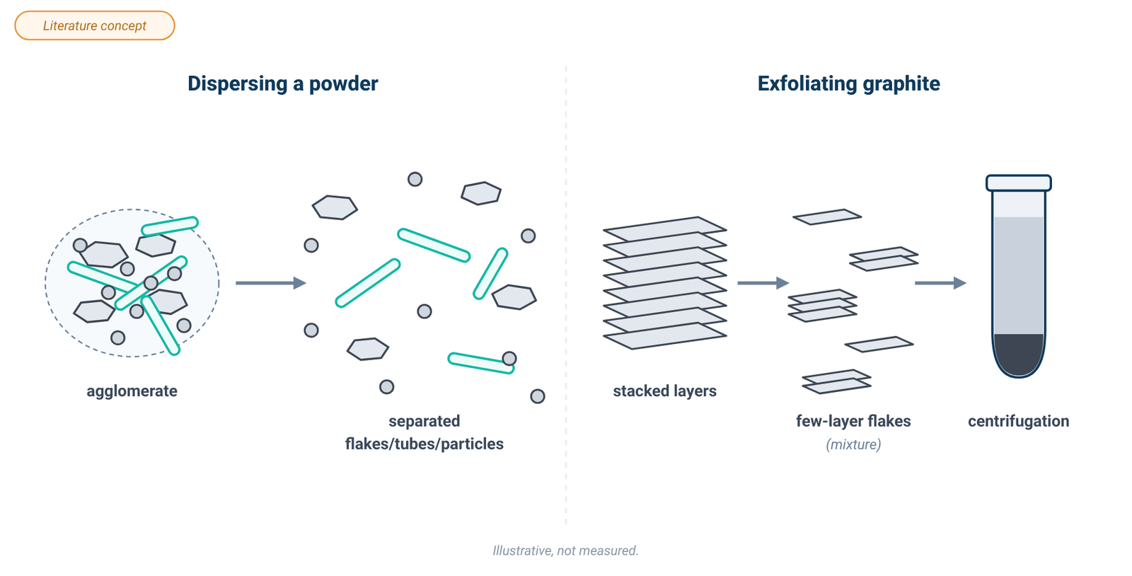
Job 1: dispersing an existing powder. Graphene nanoplatelets, graphene oxide, CNTs and nanoparticles arrive as powders whose particles have clumped into agglomerates. The task is to wet the powder, break the agglomerates apart and keep them apart. Paton and co-workers note that shear mixing "is already widely used to disperse nanoparticles in liquids", and that this generally involves breaking up "nanoparticle agglomerates which are very weakly bound compared to the inter-sheet binding strength in graphite" [4].
Job 2: exfoliating graphite into graphene. Here the layers of a crystal have to be peeled apart, which needs far more energy per particle. A widely used laboratory route is liquid-phase exfoliation by sonication: Hernandez et al. reported graphene dispersions of up to about 0.01 mg/mL in N-methylpyrrolidone with a monolayer yield of about 1% [7], and Lotya et al. extended the method to surfactant/water solutions [12].
Shear exfoliation in the literature. Paton et al. showed that graphite can also be exfoliated by high-shear mixing in a laboratory rotor–stator mixer with a "closely spaced (~120 µm) rotor/stator combination", in N-methylpyrrolidone or aqueous sodium cholate [4]. Their model and data showed exfoliation once the local shear rate exceeded about 10⁴ s⁻¹, with the shear rate estimated from rotor speed, rotor diameter and the rotor/stator gap. Exfoliation also occurred in laminar flow, so they found "turbulent energy dissipation to be unnecessary" [4]. The usable few-layer product was obtained only after centrifugation, and yields were "relatively low at <0.1%", rising to at least 3% when the sediment was recycled [4].
These results describe specific laboratory setups. No ALab™ gap width or shear rate is specified, so the literature threshold, yields and flake data cannot be mapped to any model. ACS Material does not mention graphene, nanotubes or exfoliation for these instruments, and this article makes no such claim for any instrument.
Whichever route you take, the dispersion straight out of the vessel is a mixture. Size selection by centrifugation is covered in our guide to centrifuging nanoparticles and graphene oxide, and measuring how much graphene is in suspension in our guide to graphene concentration by UV-vis. For an overview of production routes, see methods to produce graphene flake and film.
3. Graphene, Graphene Oxide and Nanoplatelet Dispersions
Sonication fragments flakes. In the original liquid-phase exfoliation work, the authors found that "sonication results in fragmentation of the initial flakes" [7]. Defects also change with time: in a bath-sonication study, "defects are located mainly at the layer edges but they turn out to build up in the bulk for ultrasonic times above 2 h" [11]. Turner et al. linked graphene exfoliation to inertial cavitation and reported that "temperature increase during sonication can result in inconsistent exfoliation", recommending temperature control and noting that shorter or pulsed runs help [13].
Probe or bath. A review of graphene and related materials reports that probe (tip) sonication gives higher production rates, while a bath puts in less energy and so is expected to fragment less, but needs longer times [9]. It also notes that bath results vary with the specific bath, its fill level and where the vial sits, and that heating must be prevented in tip sonication, bath sonication and shear exfoliation alike [9].
Shear. Paton et al. found their shear-exfoliated flakes "virtually indistinguishable from those produced by sonication both in terms of size and quality" [4]. Their laboratory runs stood in a water bath with a chiller set at 15 °C, while large-scale runs without cooling reached about 38 °C after 4 h [4]. The same review notes that, for some other layered materials, tip sonication gave better exfoliation than shear mixing [9], so the graphite result does not carry over to every material. With surfactants, turbulent shear exfoliation can foam: in a blender-type batch study, vortexing pulled air into the impeller and produced large quantities of small bubbles [8].
Graphene oxide and commercial nanoplatelets are usually Job 1 (Section 2). For a worked example of nanoplatelet dispersions at scale, see industrial-scale graphene nanoplatelets dispersions. ACS Material has no in-house test data comparing these methods; the points above come from the cited studies.
4. Carbon Nanotubes: Debundling vs Cutting
CNTs make the trade-off especially visible because sonication can improve apparent dispersion while also shortening tubes [5][6].
Sonication disperses and cuts. Huang and Terentjev describe how sonication can give "apparently enhanced dispersion through 'sonication cutting'": shorter tubes are less likely to re-aggregate and settle [5]. They add that the process can reduce SWNT bundle sizes but "it is unlikely to produce individually separated SWNTs" [5]. A scission model predicts a limiting length below which tubes stop breaking; in one test, multi-walled tubes were cut to about 2–6 µm after 3 h of sonication [6]. In composite work, long sonication shortened MWNTs to "approximately 1/3 of the original length" and caused "detrimental amorphization of the graphene walls", with a large loss in conductivity [5].
Bath for fragile tubes. The NIST protocol recommends direct (probe) sonication for dispersing dry powders but suggests indirect (bath) sonication for materials that may be damaged by a probe, giving "cleavage of single wall carbon nanotubes" as the example [1].
Shear. Huang and Terentjev's estimate that low-viscosity shear mixing offers "very little hope" was made for stirring-type Couette and melt mixing; they concluded that such mixing "is only suitable for dispersion of MWNT clusters in high-viscosity polymer melts" [5]. That conclusion is about stirring, not rotor–stator heads. The CNT review instead emphasizes that dispersion depends on mechanical processing together with surfactant or polymer stabilisation and often sonication [5]; it does not establish rotor–stator homogenizing alone as a route to CNT individualisation.
5. Metal-Oxide and Other Nanoparticles
For nanoparticle powders the NIST protocol for ultrasonic dispersion is the most practical guide, and its logic applies to any high-energy method [1]:
- Energy is power × time. "Two suspensions treated at the same power for different times can show significantly different dispersion states" [1]. Record both.
- Volume matters. Energy per unit volume sets the effect: at equal power, smaller volumes see a greater disruptive effect and also heat faster [1].
- Concentration cuts both ways. More particles mean more collisions, which can help breakage or cause particles to re-agglomerate [1].
- Measure the delivered power. NIST describes a calorimetric method for the power a probe actually delivers to the liquid [1].
- Expect it to be specific. "Sonication is a highly system-specific dispersion procedure" [1], and optimal conditions have to be found for each material and medium.
Rotor–stator mixers are used "to disperse fine solid particles in viscous liquids" [2]. For nanoparticle powders, distinguish de-agglomeration from primary-particle size reduction: the sources used here do not justify assuming that processing sets a new primary-particle size. Measure the dispersion state after processing rather than infer it from the device.
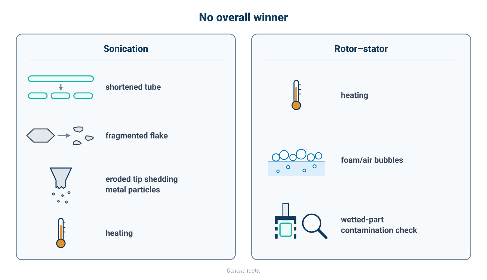
6. Damage Modes on Both Sides: No Overall Winner
Table 3. Damage modes and side effects (literature; general equipment caveats are labelled)
| Sonication (probe or bath) | Rotor–stator homogenizing |
|---|---|
| CNT shortening (scission) to a limiting length [5][6] | Heating: under turbulent conditions, shaft energy ultimately dissipates as heat [3]; cooling baths were used in laboratory studies [10] |
| Flake fragmentation, and defects that build up with time [7][11] | Air entrainment and foaming reported in turbulent shear exfoliation with surfactants [8]; setup-dependent |
| Probe-tip erosion releasing titanium particles [1] | Potential contamination from wetted parts or wear (general equipment caveat; check materials and equipment condition) |
| Strong local heating at collapsing bubbles, bulk heating of the sample, and foam with surfactants that interferes with energy delivery [1] | The CNT source used here does not establish rotor–stator mixing alone as a route to CNT individualisation [5] |
There is no overall winner. The outcome depends on the material, its concentration, the solvent or surfactant, the energy put in, the processing time and the temperature. A sensible plan is to choose the gentlest method that reaches the dispersion state you need, and to check that state rather than assume it.
7. Where Stirring Fits
In this article, stirring is not treated as a de-agglomeration step; it is used for supporting tasks such as wetting, premixing and keeping a dispersion suspended:
- Wetting and premixing. Stir the powder into the liquid before the high-energy step, so that the homogenizer or probe works on a wetted slurry rather than dry clumps.
- Moving viscous matrices. Polymer solutions and resins are easier to keep moving with an overhead stirrer than with a magnetic bar; our overhead stirrer vs magnetic stirrer guide covers torque and viscosity.
- Keeping a dispersion suspended. After dispersion, gentle stirring slows settling while a sample is used.
The OS-Pro LCD digital overhead stirrer offers "Constant speed when the viscosity of the sample changes." Its stirring-tool table lists an anchor stirrer for "medium and high viscosity materials", a spiral stirrer with the Recommended use "homogenization or suspension", and a grand anchor stirrer for "samples that precipitate easily". These are stirring tasks; this article does not present the OS-Pro as a de-agglomeration tool.
Table 4. OS-Pro overhead stirrers: separate maxima (stirring arm)
Separate maximum ratings from ACS Material specifications — not a combination one stirrer reaches at the same time.
| Separate maximum | OS20-Pro | OS40-Pro | OS70-Pro |
|---|---|---|---|
| Speed range | 50–2200 rpm | 50–2200 rpm | 50–1100 rpm |
| Max. torque | 40 N·cm | 60 N·cm | 300 N·cm |
| Max. viscosity | 10000 mPa·s | 50000 mPa·s | 100000 mPa·s |
| Power | 70 W | 130 W | 200 W |
The speed at which maximum torque applies is not specified; do not assume full rated torque at top speed. The LCD torque display is an indicator of load, not a viscosity measurement. Stirring quantities per model are listed in ACS Material's OS-Pro specifications.
8. Safe Handling
High-energy processing of nanomaterial suspensions can create aerosol exposure; for ultrasonic processing, NIST recommends a closed or covered vessel or fume hood and sufficient probe immersion [1], and equivalent exposure controls should be selected for other high-speed methods by laboratory risk assessment. Wear hearing protection near a probe sonicator (Table 1) and follow your laboratory's safety procedures for the material.
9. ALab™ Options, in ACS Material's Words
ACS Material does not sell an ultrasonic processor, so the options below are homogenizers and a stirrer. No particle size, flake size or tube length achieved is specified, and none is implied here.
D-500 — high-shear homogenizer. The D-500 high-shear homogenizer is the only one of the three described with a rotor and stator: "The motor drives the rotor at high speed, and the sample is homogenized or dispersed in the gap between the rotor and the stator, usually in a short period of time." ACS Material lists "Max. linear velocity 22.7–36 m/s" as one range for the instrument, and its listed dispersing heads cover 10–5000 mL (DS-500/1, DS-500/2) and 1–50 mL (DS-500/5). Its maximum viscosity, as a separate rating, is 10000 mPa·s. Among its typical tasks ACS Material lists "pigment and resin dispersion", "suspensions and emulsions" and "dissolving solids". Rotor–stator processing can generate heat; monitor sample temperature and cool as needed [3][10].
D-200 — benchtop homogenizing emulsifier. The D-200 benchtop homogenizing emulsifier is described this way: "Its internal suction structure homogenizes and emulsifies immiscible liquids at high speed." It lists 2000–20000 rpm, a processing volume of 20–1200 mL with two blade sets, and an operating mode of "Continuous operation for approx. 15 min". No tip speed or noise level is specified. No sample temperature-rise value is specified, so monitor sample temperature and cool as needed.
D-160 — handheld homogenizer. The D-160 handheld homogenizer is a "portable, lightweight homogenizer" with three dispersing shafts for 0.1–50 mL, 1–150 mL and 1–250 mL; each shaft is described as a "Dispersing tool for solid/liquid media; small amounts of solid/liquid mixtures." No sample temperature-rise value is specified, so monitor sample temperature and cool as needed.
OS-Pro — overhead stirrer. For premixing and keeping batches suspended (Section 7).
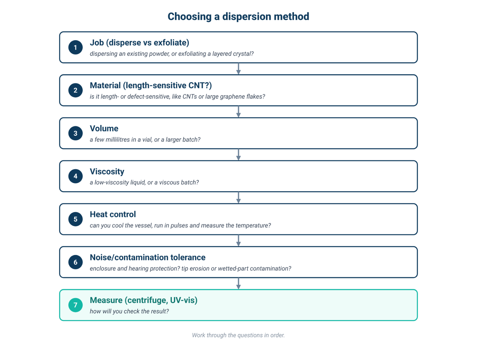
10. Method-Choice Checklist
- Job: dispersing an existing powder, or exfoliating a layered crystal (Section 2)?
- Material: is it length- or defect-sensitive, like CNTs or large graphene flakes (Sections 3–4)?
- Volume and viscosity: a few millilitres in a vial, or a larger or viscous batch?
- Heat: can you cool the vessel, run in pulses and measure the temperature?
- Noise and contamination: can you use an enclosure and hearing protection, and tolerate tip erosion or possible contamination from wetted parts?
- Surfactant: will it foam under turbulence or cavitation?
- Measurement: how will you check the result, for example by centrifugation and UV-vis?
11. Frequently Asked Questions
Is a homogenizer better than a sonicator?
Neither is better in general. They break material up in different ways and damage it in different ways (Section 6). The right choice depends on the material, volume, viscosity and how much heat and contamination you can accept.
Can a homogenizer make graphene from graphite?
In the literature, yes, under specific conditions: Paton et al. exfoliated graphite with a laboratory rotor–stator mixer in suitable liquids, with low yields and centrifugation afterwards [4]. That is a literature result, not a property of any particular instrument.
Why do my nanotubes get shorter?
Sonication can shorten CNTs toward a limiting length [5][6]. If probe damage is a concern, NIST suggests indirect bath sonication for materials such as SWCNTs that may be cleaved by direct sonication [1].
Probe or bath sonication?
A probe delivers more energy and is more reproducible; a bath puts in less energy, treats the sample in its own container and needs longer times [1][9].
Why does my sample heat up?
Both methods can heat the sample: under turbulent rotor–stator operation, shaft energy is ultimately dissipated as heat [3], while ultrasonic processing can heat the liquid [1]. Use cooling, pulse operation where appropriate and temperature monitoring.
Do I need hearing protection?
For probe sonication, NIST recommends an acoustic enclosure and ear plugs (NRR 30/SNR 34) and/or ear muffs near the source [1].
Choosing equipment for dispersion or emulsification tasks? See the D-500 high-shear homogenizer for its listed dispersion and emulsion tasks, and the D-200 benchtop homogenizing emulsifier for its listed homogenization and emulsification use.
12. Keep Exploring the Mixing Hub
- Laboratory mixing methods guide: every mixing method compared.
- Rotor–stator homogenizers and tip speed: tip speed, shear rate and dispersing tools.
- Centrifugation for nanoparticles and graphene oxide: size selection after dispersion.
- Graphene concentration by UV-Vis: measure what you dispersed.
- Graphene nanoplatelets for plasmonic Pickering emulsions: nanoplatelets at a liquid interface.