
Heat sealing and vacuum-assisted joining are used in thin-film labs to close pouches, bond cover sheets and press stacks together. The joint depends on the temperature reached at the interface, a modest contact pressure, enough dwell time and a clean, compatible interface. This guide explains those variables, what vacuum can and cannot do, how sealing differs from laminating, and how to qualify a joint.
In one paragraph: For polyethylene films, seal properties were set mainly by the maximum interface temperature; dwell only had to be long enough to reach it, and slight pressure for contact was enough [2]. Seal initiation tracks the melting behaviour of the polymer [1]. Vacuum reduces trapped gas but does not guarantee a void-free joint [4]. Seal strength (ASTM F88) is not barrier performance [3][5].
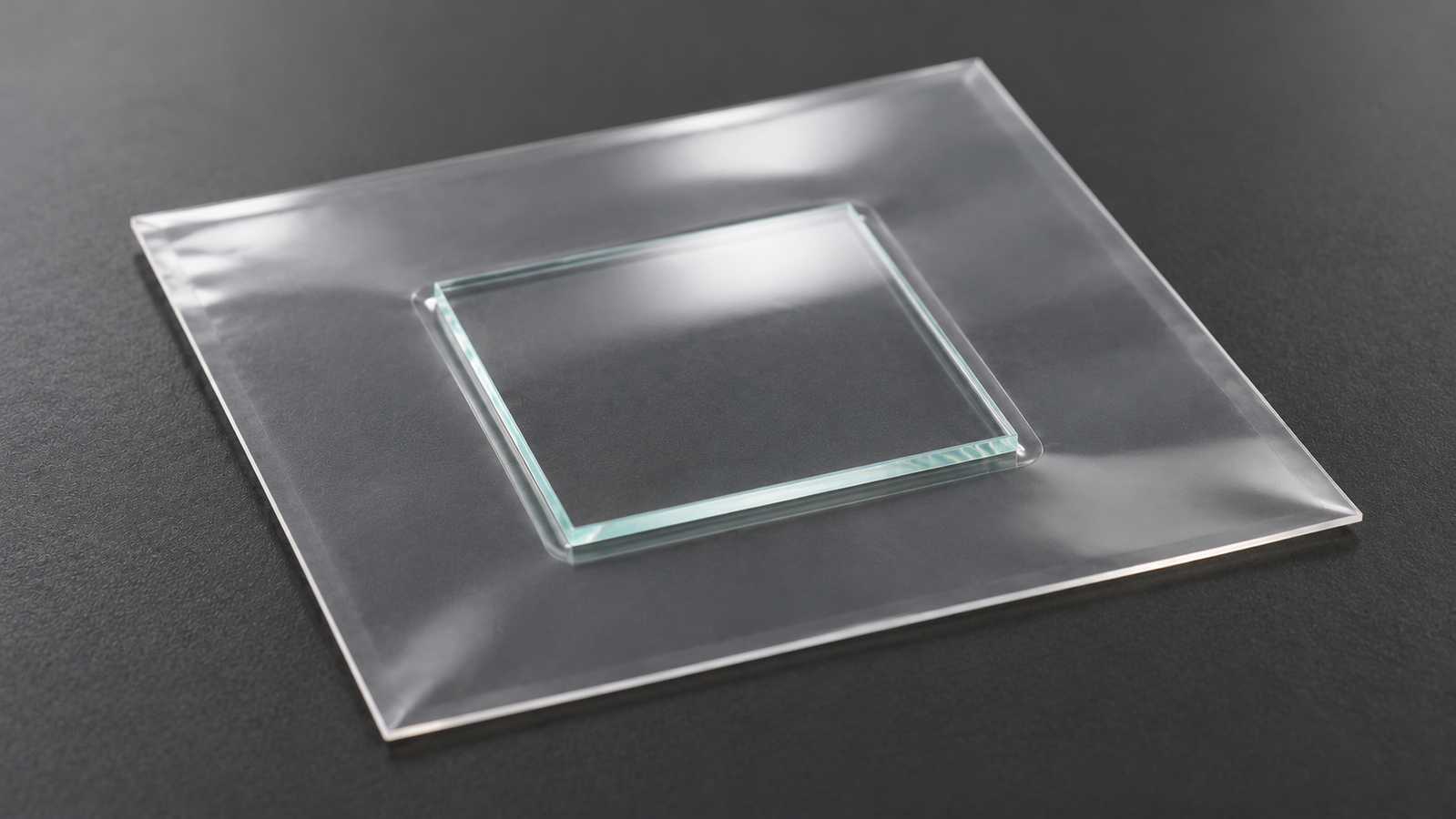
1. What Heat Sealing and Vacuum-Assisted Joining Are
Heat sealing joins two layers by bringing them into contact under heat and pressure for a set time, so that a thermoplastic layer at the interface softens or melts, wets the opposite surface and solidifies into a joint. Stehling and Meka describe it, for polymer films, as the formation of a joint between two films by placing them briefly between heated platens [1]. Vacuum-assisted joining adds one more element: the air between the layers is pumped out before or during pressing.
In a thin-film laboratory the same physics appears in several jobs: closing a pouch or bag around a sample, bonding a cover film or sheet to a coated substrate, or pressing a stack of layers together. This guide covers the process variables that control the joint, what vacuum does and does not do, how sealing differs from laminating, and how to check that a joint is reproducible. It is not a validated recipe for any particular material stack.
2. Temperature, Pressure, Dwell Time and the Interface
Four variables control a heat-sealed joint: temperature, pressure, dwell time and the interface itself. Meka and Stehling measured the interfacial temperature during sealing of polyethylene films with micro-thermocouples, compared it with finite element calculations, and quantified how seal bar temperature, dwell time and pressure affected seal strength, elongation and seal energy [2]. Their findings for those films are a useful frame:
| Variable | What the study found for polyethylene films [2] | Practical reading |
|---|---|---|
| Temperature | Seal properties are determined primarily by the maximum temperature reached at the interface | Platen set-point is not interface temperature; heat must pass through the outer layers first |
| Dwell time | Must be long enough to bring the interface to the desired temperature; longer times at a given interfacial temperature did not improve seal properties | Thicker or less conductive stacks need longer dwell to reach the same interface temperature |
| Pressure | A slight pressure helped bring the surfaces into contact; higher pressure did not improve seal properties in the study | For these polyethylene films, higher pressure did not improve seal properties; qualify pressure for other materials |
| Excess heat | Increased pressure and dwell at temperatures above the final melting point were detrimental to seal appearance due to deformation | Excess heat, pressure and dwell can deform the joint; qualify the process for the material |
Summary of Meka and Stehling [2]; results apply to the polyethylene films and conditions studied.
The second paper in the same series linked sealing temperature to the melting behaviour of the polymer. For polyethylene films, the seal initiation temperature corresponded to the temperature at which the amorphous fraction reached 77±3%; seal strength then rose with the amorphous fraction and reached a plateau at the final melting point, with the plateau strength set by the yield stress of the film [1]. The practical message is that a sealing window should be found from the material’s melting behaviour and a temperature series, not assumed from another material.
The interface
Contamination, moisture, surface texture and the compatibility of the two surfaces all affect whether molten polymer wets and bonds. A sealant that bonds well to one film may bond poorly to glass, metal or a coated surface. Surface preparation is covered in Substrate Cleaning Protocol for Thin-Film Devices: Solvents, UV-Ozone, Plasma and Queue Time and wetting in Why Your Ink Dewets: Surface Energy, Contact Angle and Wetting Before You Coat.
3. What Vacuum Does, and What It Does Not
Air trapped between two layers can form voids or bubbles in the joint and can hold the layers apart. Pumping the stack down before pressing reduces the amount of gas available to be trapped. It does not guarantee a void-free joint: gas or vapor can also come from the materials themselves, from moisture or from reactions during heating, and the polymer must still flow and wet the surfaces.
A published example from photovoltaic module lamination illustrates this. Wu and co-workers studied how lamination conditions affect EVA encapsulant stability, using curing level, void generation, chemical and optical stability and adhesion as indicators. They found that laminate stability increased with curing level up to an upper limit, beyond which voids formed, transmittance stability fell, discolouration appeared and interfaces became unstable; for the materials they tested, the best gel content range was 84–90% [4]. That result is specific to the EVA materials in the study, but it shows that more heat is not always better and that voids can form even in a vacuum laminator.
Vacuum level, pump-down time before pressing, and the order in which vacuum and pressure are applied are therefore process variables to record and test, alongside temperature, pressure and dwell.
4. Sealing vs Laminating
| Sealing | Laminating | |
|---|---|---|
| Typical goal | A joint along an edge or perimeter (for example, closing a pouch) | Bonding over a whole area (for example, a cover sheet over a sample) |
| Heat path | Through a narrow seal area | Through the full stack area |
| Main risks | Weak or channelled seal, edge deformation | Trapped gas, voids, uneven thickness, thermal stress across the sample |
| Role of vacuum | Removes air from inside a pouch before closing | Removes air between layers before pressing |
General comparison; actual practice depends on materials and geometry.
Both use the same variables. Laminating usually heats the whole sample, so the thermal limits of every layer in the stack matter, not only those of the adhesive or sealant.
5. A Strong Joint Is Not a Barrier
A strong joint is not the same as a barrier. Mechanical seal strength says nothing directly about how fast moisture or oxygen pass through the materials or along the interface.
- Kempe and co-workers explain that thin-film photovoltaic technologies can be sensitive to corrosion from water vapor, and that modules typically use impermeable front and back sheets with an edge seal, often a desiccant-filled polyisobutylene, to slow ingress. They note that even the lowest-diffusivity transparent encapsulant materials are insufficient for the lifetime of a module on their own, and they used a calcium-film optical method to measure ingress [5].
- Lewis and Weaver note that polymer substrates do not offer the same barrier performance as glass, so OLEDs on polymer substrates need thin-film barriers on both sides of the device layers for sufficient lifetimes [6].
Barrier performance therefore depends on the materials and the design of the whole package, and must be measured with methods intended for permeation or ingress, not inferred from a successful seal.
6. Qualifying a Joint: Seal Strength, Damage and Repeatability
ASTM F88/F88M covers the measurement of seal strength in flexible barrier materials. It measures the force required to separate a test strip containing a seal and identifies the failure mode; its scope includes seals between flexible materials and between flexible and rigid or semi-rigid materials [3]. Use it only where the specimen and seal fall within the standard’s scope. For other thin-film joints or full-area laminates, select a test method appropriate to the geometry and intended failure mode. ASTM F88/F88M describes seal strength as a quantitative measure for process validation, capability and control, and recommends consistent use of one test technique because unsupported, supported 90° and supported 180° configurations can give different results [3].
For thin-film samples, qualification of a sealing or laminating step usually needs more than one check:
| Check | What it shows |
|---|---|
| Seal strength and failure mode (for example, ASTM F88) | Mechanical integrity of the joint; whether it fails in the seal or the material [3] |
| Visual and optical inspection of the joint | Voids, channels, wrinkles, deformation |
| Device or film measurement before and after | Whether heat or pressure changed the sample |
| Interface temperature, if it can be measured | Actual thermal exposure rather than set-point [2] |
| Repeat runs with recorded settings | Repeatability of the process |
| Permeation or ingress tests where needed | Barrier performance, which seal strength does not show [5] |
General qualification checklist.
Thin-film sample considerations
- Thermal budget. Organic, perovskite and polymer layers can change at temperatures that a sealant needs. Know the limit of the most sensitive layer before choosing a sealing temperature; annealing behaviour is discussed in Soft Bake, Post-Bake and Annealing on a Hot Plate: What Each Step Does.
- Pressure on fragile layers. In the polyethylene study, slight pressure was enough for contact [2]; for other stacks, start low and raise pressure only as far as needed for a consistent joint.
- Atmosphere. Air-sensitive samples may need to be handled under an inert atmosphere before closing; see Annealing Under Nitrogen: Inert Hot Plates for Air-Sensitive Films.
- Thickness. Measuring layer thickness before and after can reveal flow or compression; methods are compared in How to Measure Thin Film Thickness: Profilometry, Ellipsometry and Interference.
Application areas where these steps appear in the literature include photovoltaic modules [4][5] and flexible OLEDs [6]. These are general examples of the technique, not qualified uses of any particular instrument.
7. Levon™ HS150 and HS320-CTM-ZK: Published Specifications
The Levon™ HS150 is a benchtop heat sealer with a 150 × 150 mm panel and a published temperature range of RT to 250°C. The Levon™ HS320-CTM-ZK is a vacuum heat sealer/laminator capable of sealing 300 × 300 mm samples, with a published temperature range of RT to 180°C, vacuum below 100 Pa, and adjustable vacuum and jacking pressure. These specifications describe the equipment, not a validated sealing recipe for every thin-film stack. Confirm material compatibility, seal geometry, operating conditions and the intended application with the supplier.
| Specification | HS150 | HS320-CTM-ZK |
|---|---|---|
| Type (page title) | Benchtop heat sealer / laminator | Vacuum heat sealer / laminator |
| Sample / panel size | Panel size 150 × 150 mm | Capable of sealing 300 × 300 mm samples |
| Temperature range | RT to 250 °C | RT to 180 °C |
| Resolution | 0.1 °C (after the temperature is stabilized) | 0.1 °C |
| Accuracy / precision | Accuracy ≤±0.2 °C | Precision ±1 °C |
| Published temperature-uniformity notation | ≤±2% (calculation basis not stated) | ≤±2% (calculation basis not stated) |
| Temperature control | PID, dual-zone | Not stated |
| Published vacuum level (test conditions not stated) | Not stated | Below 100 Pa |
| Adjustable parameters | Not stated | Jacking pressure; vacuum level |
| Compressed air / gas supply | 0.4–0.8 MPa; air inlet 6 mm OD | 0.4–0.8 MPa; gas interface 6 mm OD |
| Other published features | Emergency power cutoff; compact form factor for glove box integration | Automatic heat sealing |
| Power | AC 200–240 V, single-phase, 50 Hz, 2.0 kW | AC 200–240 V, single-phase, 50 Hz, 2.0 kW |
| Dimensions (W × D × H) | 200 × 200 × 340 mm; 10 kg | 560 × 650 × 400 mm; 70 kg |
Specifications as published on the Levon™ product pages on 24 October 2026. The supplied configuration is confirmed in the quotation. “Not stated” means the page does not give the value. The published ≤±2% uniformity notation is reproduced as stated; its reference basis and calculation method are not provided, so it should not be treated as a fully defined temperature tolerance.
How this connects to the guide: the two models are not interchangeable. The HS320-CTM-ZK page publishes a vacuum level below 100 Pa and adjustable vacuum and jacking pressure, but does not state the validated operating pressure during sealing or the jacking-pressure range. The published temperature ranges and sample sizes also differ. As Section 2 explains, the interface temperature, dwell and pressure must be qualified for the intended process. The Levon™ HS150 Benchtop Heat Sealer and the Levon™ HS320-CTM-ZK Vacuum Heat Sealer can be discussed through the contact form.
8. Keep Exploring the Thin-Film Processing Knowledge Hub
Related guides
- Substrate Cleaning Protocol for Thin-Film Devices: Solvents, UV-Ozone, Plasma and Queue Time — surface preparation before joining
- Reading Hot Plate Specs: Temperature Uniformity, Accuracy and What ±1% Means — what temperature uniformity figures mean
- Annealing Under Nitrogen: Inert Hot Plates for Air-Sensitive Films — handling air-sensitive films under nitrogen
- Solution-Processed OLED and OPV Layers: Thickness Targets and a Lab Process Flow — solution-processed OLED and OPV layers
- How to Measure Thin Film Thickness: Profilometry, Ellipsometry and Interference — measuring film thickness before and after a process
Links will be added as each article is published.
Equipment
- Levon™ HS150 Benchtop Heat Sealer — 150 × 150 mm panel; RT to 250 °C
- Levon™ HS320-CTM-ZK Vacuum Heat Sealer — seals 300 × 300 mm samples; RT to 180 °C; vacuum below 100 Pa
Questions about a specific instrument can be sent through the contact form.
9. FAQ
What controls the strength of a heat seal?
For polyethylene films, mainly the maximum temperature reached at the interface [2].
Does more pressure make a stronger seal?
In the polyethylene study, slight pressure helped contact but higher pressure gave no benefit [2].
Does a longer dwell time help?
Only until the interface reaches the target temperature; beyond that it did not improve seal properties in that study [2].
What does vacuum do in a vacuum heat sealer?
It removes air before pressing, reducing trapped gas, but voids can still form from the materials or the process [4].
How is seal strength measured?
ASTM F88/F88M measures the force to separate a strip containing the seal and records the failure mode [3].
Is a strong seal also a moisture barrier?
No. Barrier performance depends on the materials and package design and must be measured separately [5][6].