
Substrate contamination can cause coating defects that resemble ink or recipe problems. This guide builds a substrate cleaning protocol from published practice: solvents, a dry oxidising clean, a dehydration bake where needed, and a defined queue time before coating.
In one paragraph: Choose a substrate-compatible solvent clean, then a qualified UV-ozone or oxygen-plasma treatment where needed [3][6]. Dehydration and adhesion promotion are process-specific preparation steps, not requirements for every coating [1]. Coat at the specified substrate temperature within a queue time qualified for the final prepared surface.
1. Why Cleaning Is a Protocol, Not a Step
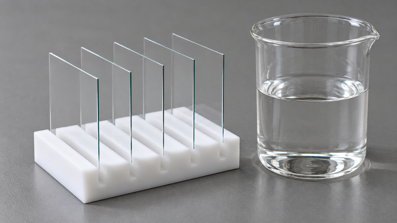
A thin film is only as good as the surface under it. Particles cause pinholes and comets, organic films cause dewetting and poor adhesion, and adsorbed water changes how a resist or ink wets. No single cleaning step removes all of these, which is why reliable labs write the clean down as a protocol: an ordered sequence of steps, each removing one kind of contamination, ending with a defined wait before coating.
This guide builds that sequence from published practice. It covers what each step removes, the order that keeps one step from undoing another, and the time between the last clean and the coating, which is easy to overlook. Exact recipes depend on your substrate and film, so treat the sequence as a framework to qualify, not a recipe to copy.
| Contamination | Typical effect on the film | Step that addresses it |
|---|---|---|
| Particles | Comets, pinholes, local thickness defects | Solvent rinse; clean handling and storage [1] |
| Organic films (oils, residues, airborne hydrocarbons) | Dewetting, poor adhesion, high water contact angle | Solvent clean, then UV-ozone or plasma [1][2][3] |
| Heavy organic or metallic contamination on silicon | Device-level defects before high-temperature steps | Wet chemical cleans such as piranha and RCA [1][4] |
| Adsorbed water | Changes resist wetting and adhesion | Dehydration bake where the process requires it [1] |
Summary of the cited sources. The steps you need depend on substrate, film and contamination level.
2. Step One: Solvents and Wet Chemistry
Solvents first. For compatible substrates in its photoresist-preparation context, the cited application note recommends a two-stage clean in acetone followed by isopropanol (IPA), which removes the contaminated acetone before it can dry into streaks [1]. For heavier contamination or larger batches, it describes a cascade: acetone I, acetone II, IPA I, IPA II, with the dirtier bath replaced by the cleaner one at intervals to save solvent. For that solvent sequence, a subsequent deionised (DI) water rinse is not recommended, because insufficiently clean water can undo the IPA clean [1]. For particles alone, an IPA rinse is the suggested step.
Wet chemistry for silicon. For certain contaminated silicon wafers, the cited application note describes piranha followed by RCA cleaning [1]. Kern’s review traces how the RCA sequence developed and why it became the reference wet clean for silicon [4]. These solutions are strongly oxidising, corrosive or both, and are run only under the chemical safety rules of your institution.
ITO and other coated glass. The preparation and characterisation of indium tin oxide (ITO) substrates for organic light-emitting devices has been studied in its own right [5], and the ITO work function depends on how the surface was cleaned [2]. Whatever wet sequence you choose, keep it identical from batch to batch.
3. Step Two: The Dry Oxidising Clean
Solvent cleaning reduces organic contamination but cannot be relied on to remove the last thin organic film. A qualified UV-ozone or oxygen-plasma treatment can reduce residual organic contamination and improve wetting on compatible surfaces [3][6]. UV-ozone cleaning works best on surfaces that have been pre-cleaned to remove gross contamination [3]. Place the dry oxidising clean after wet cleaning and drying, but before any intentional adhesion-promoter treatment required by the qualified coating process.
- UV-ozone works at atmospheric pressure. Short-wavelength UV forms ozone and atomic oxygen that oxidise organic films into volatile products [3][7]. Air-based operation avoids a vacuum process chamber; confirm installation utilities and the required ozone containment and exhaust [8]. See UV-Ozone Cleaning Explained: 185 nm, 254 nm and What Reaches the Surface.
- Oxygen plasma works at low pressure in a vacuum chamber, with ions, radicals and UV acting together. See Plasma Cleaning Explained: How Plasma Removes Nanoscale Contamination and Benchtop Plasma Cleaners Compared: 25 kHz, 40 kHz and 13.56 MHz.
On ITO, the work function depends on the cleaning method used [2], and oxidising treatments that activate the surface have been studied in detail [9]. How the two compare on glass and ITO is covered in UV-Ozone vs Oxygen Plasma for ITO and Glass: Which Clean Before Coating?.
4. Dehydration Bake and Adhesion Promoters
Surfaces exposed to room air carry adsorbed water. For clean substrates in its photoresist-preparation context, the cited note recommends a bake at about 120 °C for a few minutes to desorb it, and notes that the step can be skipped if the substrate was cleaned immediately before with IPA or was heated above 100 °C in a previous process step [1]. For oxidised surfaces, the same note discusses baking above 140 °C to improve resist adhesion [1]; this is source-specific guidance, not a universal threshold for every oxide or coating.
Water can re-adsorb within a short time, depending on humidity and substrate, so coating should follow the bake as soon as possible, after cooling to the temperature specified by the coating recipe [1]. Coating a warm substrate changes evaporation during spinning; see Heated Spin Coating: How Substrate Temperature Changes Evaporation and Thickness.
Adhesion promoters for photoresists. For some photoresists on oxide surfaces, hexamethyldisilazane (HMDS) can improve adhesion by modifying the surface chemistry and making it more hydrophobic. Applied as a vapour onto a substrate at 75–120 °C, HMDS binds chemically as a monolayer; spun on as a liquid, much of it is only physically bound and can release ammonia that affects the resist near the interface [1]. On noble metals without a native oxide, such as gold or platinum, organic adhesion promoters help little [1]. The appropriate surface preparation depends on the actual resist or ink, not simply whether it is water-based. For ink wetting, see Why Your Ink Dewets: Surface Energy, Contact Angle and Wetting Before You Coat.
5. Queue Time: The Step Most Protocols Leave Out
A freshly cleaned surface starts to change as soon as it leaves the cleaner. Li and co-workers observed airborne hydrocarbon adsorption and increasing water contact angle on supported graphene and graphite [10]. Plasma-treated polymers lose part of their wettability as the surface reorganises, a process called hydrophobic recovery [11]. On ITO, the work function after UV-ozone treatment has been measured to change with time [12].
So the protocol should state a queue time: the qualified interval from the specified final preparation step to coating, including cooling and storage. Choose it by test, not by habit. Prepare matched substrates, hold them for different times under the intended handling and storage conditions, and evaluate suitable surface and coating or device tests. ASTM C813 gives a contact-angle method for detecting hydrophobic contamination on glass that suits this kind of check [13]. If the queue time is exceeded, follow the qualified rework procedure; do not automatically repeat an oxidising clean on a primed or otherwise modified surface.
6. An Example Protocol to Adapt
The table assembles the steps above into one example sequence for glass or ITO-coated glass before a solution-processed layer. Every value comes from the cited sources or is marked as yours to set.
| Step | Purpose | Example from the cited sources | Set and record |
|---|---|---|---|
| 1. Solvent clean | Remove organics and particles | Acetone, then IPA; cascade for heavy loads; no final DI rinse in that cited solvent sequence [1] | Baths, times, solvent change interval |
| 2. Dry | Remove solvent without residue | Not specified in the cited sources; use a method that leaves no residue | Method (gas blow-off or spin dry) |
| 3. Dry oxidising clean | Reduce residual organics; prepare the required surface | UV-ozone or oxygen plasma [3][6] | Instrument, time, power or lamp distance, gas |
| 4. Dehydration bake (resists) | Desorb water where required by the resist process | About 120 °C for a few minutes; above 140 °C for oxidised surfaces [1] | Temperature, time, hot plate |
| 5. Adhesion promoter (resists) | Improve resist adhesion where the process requires it | HMDS vapour onto a 75–120 °C substrate [1] | Method and temperature |
| 6. Cool and coat | Coat at the specified substrate temperature | Coat after cooling; within the queue time [1][10] | Coating temperature; qualified queue time |
An example framework, not a qualified recipe. Steps 4 and 5 apply to photoresists; do not apply HMDS by default before water-based inks. Wet chemical cleans for silicon (piranha, RCA) are covered in the cited sources [1][4].
Record the answers in the right-hand column in your process sheet. When a coating fails, a written protocol lets you change one variable at a time instead of guessing.
7. Levon™ UV-Ozone and Plasma Cleaners
The tables quote the Levon™ product pages; “Not stated” means the page does not give the value.
| Specification | UC100-SE | UC200-SE |
|---|---|---|
| Lamp | 300 W U-shaped lamp; 185 nm + 254 nm | 300 W lamp; 185 nm + 254 nm |
| Cleaning area | ≤8 in | ≤8 in |
| Published illumination / irradiation height | 35 mm illumination height | 31–44 mm irradiation height (substrate thickness excluded), set by jacking |
| Heating | Not stated | 500 W hot plate; RT to 200 °C |
| Continuous cleaning time (published) | 99.99 h | 99.99 h |
| Ozone concentration at the sample | Not stated | Not stated |
Specifications as published on the Levon™ UV-ozone cleaner product pages on 22 October 2026. The supplied configuration is confirmed in the quotation.
| Specification | PT500 | PT13M | PT40K |
|---|---|---|---|
| Frequency | 25 kHz | 13.56 MHz, automatic matching | 40 kHz, automatic matching |
| Power | 0–500 W, adjustable | GE, SE: 0–300 W; BE: 0–200 W (maximum 300 W) | BE: 0–500 W (maximum 1,000 W); SE: 0–1,000 W |
| Chamber | Ø150 × 152 mm, aluminum alloy (larger sizes can be customized) | 226 × 126 × 224 mm, 6.4 L, aluminum alloy | 226 × 126 × 224 mm, 6.4 L, aluminum alloy |
| Vacuum level | ≤100 Pa | <10 Pa | <10 Pa |
| Gas control | Single gas path, 0.1–1 L/min | GE: dual MFC; BE: single float flowmeter; SE: dual float flowmeters | BE: single float flowmeter; SE: dual float flowmeters |
| Time setting | 1–200 s, continuously adjustable | GE, SE: 6,000 s; BE: 999 s | 300 s |
| Substrates | Not stated (chamber size above) | Under 8 inches; complex shapes | Up to 8 inches (200 mm) |
| Vacuum pump pumping speed | Not stated | GE, SE: 8 m3/h; BE: 4 m3/h | 4 m3/h |
| Gas stabilization time | Not stated | GE, SE: 30 s; BE: 40 s | 30 s |
| Process gases named | Not stated | Not stated | Not stated |
| Dimensions (W × D × H) | 452 × 386 × 225 mm; approx. 18 kg | 620 × 550 × 410 mm | 500 × 480 × 290 mm |
Specifications as published on the Levon™ UV-ozone and plasma cleaner product pages on 22 October 2026. All five pages state that external utilities, where required, are supplied by the user. The supplied configuration is confirmed in the quotation.
How this connects to the guide: UV-ozone is an option for step 3; use a plasma cleaner for that oxidising step only after confirming the required gas and process compatibility. The UC100-SE and UC200-SE are UV-ozone options whose installation utilities and exhaust requirements should be confirmed; the UC200-SE adds a hot plate to 200 °C under the lamp. The PT500, PT40K and PT13M run at low pressure; ask which process gases each supports, since the pages do not name them. For step 4, the dehydration bake, see the Levon™ hot plates.
8. Keep Exploring the Surface Preparation Knowledge Hub
Start here
- Solution-Processed Thin Films: Choosing Spin, Dip, Slot-Die or Blade Coating — the coating methods this protocol prepares for
- UV-Ozone Cleaning Explained: 185 nm, 254 nm and What Reaches the Surface — how UV-ozone cleaning works
- UV-Ozone vs Oxygen Plasma for ITO and Glass: Which Clean Before Coating? — the two dry cleans compared for ITO and glass
Process guides
- Benchtop Plasma Cleaners Compared: 25 kHz, 40 kHz and 13.56 MHz — choosing a benchtop plasma cleaner
- Why Your Ink Dewets: Surface Energy, Contact Angle and Wetting Before You Coat — surface energy, contact angle and dewetting
- Plasma Cleaning Explained: How Plasma Removes Nanoscale Contamination — what plasma removes from a surface
- Spin Coating Defects: Comets, Striations, Pinholes and Edge Beads Diagnosed — defects that point back to the substrate
- Heated Spin Coating: How Substrate Temperature Changes Evaporation and Thickness — why substrate temperature matters at coating
Links will be added as each article is published.
Equipment
- UC100-SE UV-Ozone Cleaner — 300 W lamp, 185 + 254 nm, up to 8 in
- UC200-SE Heated UV-Ozone Cleaner — adds a hot plate to 200 °C
- PT13M RF Plasma Cleaner — 13.56 MHz, automatic matching
- Levon™ UV-Ozone Cleaners — all UV-ozone cleaners
- Levon™ Plasma Cleaners — all plasma cleaners
- Levon™ Hot Plates — for the dehydration bake
Questions about a specific cleaner can be sent through the contact form.
9. FAQ
Should I rinse in DI water after IPA?
The cited photoresist note does not recommend a final DI rinse after its acetone/IPA sequence [1]. This is not a no-water rule for other cleaning chemistries; follow the qualified rinse and drying requirements of the chosen process.
Where does UV-ozone or plasma go in the sequence?
After wet cleaning and drying, and before any intentional adhesion-promoter treatment required by the qualified process [3][6].
Do I always need a dehydration bake?
It is recommended for resists on clean substrates exposed to humid air, and can be skipped right after an IPA clean or a step above 100 °C [1]. Coat at the temperature specified by the qualified recipe.
Should I use HMDS before every coating?
No. On oxide surfaces, HMDS can improve adhesion for some photoresists by making the surface more hydrophobic [1]. Do not apply it by default before an aqueous ink; qualify the resulting wetting and film performance.
How long can a cleaned substrate wait?
There is no universal value. Prepared surfaces change with time, as reported for graphene and graphite [10] and UV-ozone-treated ITO [12], and treated polymers recover [11], so qualify a queue time by testing wetting or film quality after different waits [13].