
An ink that pulls back may reflect the surface, formulation or coating conditions; the symptom alone does not identify the cause. This guide explains dewetting with Young’s equation and surface energy, lists why clean surfaces stop wetting, and gives a diagnostic table to use before you change the ink.
In one paragraph: Wetting depends on the liquid, solid and their interface [2][3]. Check surface preparation, ink condition and process history together. Contact-angle measurements can support diagnosis, but do not alone predict drying stability or adhesion. Qualify any cleaning, priming or formulation change with the actual coating and its intended use.
1. What Dewetting Is, and Two Kinds to Separate
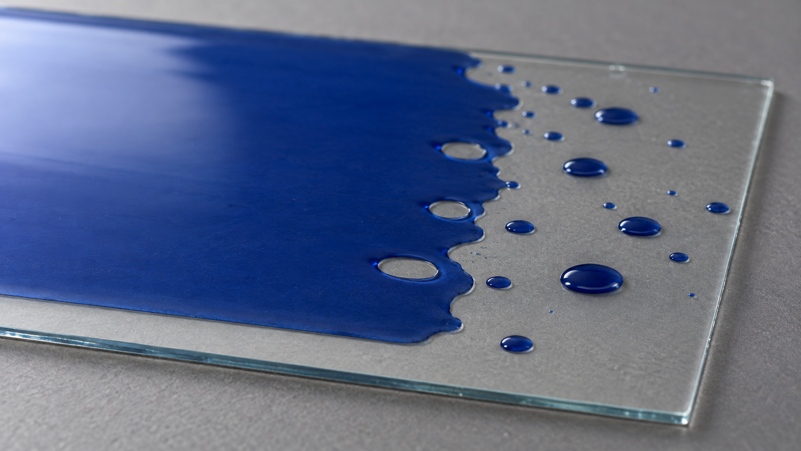
Dewetting is a coating pulling back from the surface it was meant to cover. It shows up as an ink that retracts from the edges of a substrate, holes that open and grow in a wet or freshly dried film, or a layer that breaks into droplets and islands. It wastes substrates and ink, so compare surface preparation, formulation and process conditions before assigning a cause.
Two situations are worth separating, because they have different remedies:
- The liquid does not wet the surface. The wet film retracts during dispensing, spinning, blading or drying, because the balance of surface energies favours a bare substrate over a covered one. Investigate the liquid-surface combination and the coating conditions rather than assuming a cleaning fault.
- A thin solid film dewets later. A very thin film on a substrate it does not wet can be stable while glassy but rupture and form growing holes when it is heated and becomes mobile; Reiter showed this for thin polymer films [1]. Here the anneal triggers what the surface energies allow.
Both trace back to the same quantities: the surface energy of the substrate, the surface tension of the liquid and the energy of the interface between them.
2. Contact Angle, Young’s Equation and the Spreading Coefficient
For an ideal smooth, chemically uniform solid in partial-wetting equilibrium, the contact angle θ is related to three interfacial tensions: solid–vapour (γSV), solid–liquid (γSL) and liquid–vapour (γ). Young’s relation links them [2][3]:
γSV = γSL + γ cos θ
A smaller contact angle means better wetting; a large one means the liquid beads. De Gennes framed the same balance as a spreading coefficient, S = γSV − (γSL + γ) [3]. When S is positive, a liquid wets the solid completely and a film is favoured; when S is negative, the liquid settles at a finite contact angle, and a thin film of it can be unstable and dewet [3].
For coating, compare the actual liquid-solid pair: the solid-liquid interfacial energy matters as well as the solid surface energy and liquid surface tension. Cleaning, activation or a formulation change may improve wetting, but each must be checked for material compatibility and final-film performance.
Real surfaces are rough and chemically uneven, so the contact angle observed while a drop advances differs from the angle while it recedes. That difference is contact angle hysteresis. It affects contact-line pinning, but does not by itself explain later film rupture or retraction [3].
3. Surface Energy Has Components: Matching Ink to Surface
Surface energy is not one number in practice. Fowkes proposed splitting it into a dispersion component, from forces present between all molecules, and contributions from more specific interactions [4]. Owens and Wendt extended this into a widely used method: measure contact angles of two liquids, water and methylene iodide, and estimate a dispersion component and a polar plus hydrogen-bonding component for the solid [5].
Why this helps diagnosis: two surfaces with the same water contact angle can have different components, and a liquid’s wetting depends on how its own components match the solid’s. For some photoresists on oxide surfaces, the cited preparation note recommends an adhesion promoter such as HMDS [6]. This is process-specific adhesion guidance, not a universal rule that resists require low-energy surfaces. Qualify wetting and dried-film adhesion separately for the actual formulation.
| Ink or liquid | Surface condition to qualify | Typical preparation |
|---|---|---|
| Water-based or strongly polar ink | High surface energy, large polar component | Solvent clean, then UV-ozone or plasma [7][8] |
| Photoresist on an oxide | As specified for the resist and process | Dehydration and HMDS where required by the qualified process [6] |
| Low-surface-tension organic solution | Clean surface; a low-tension liquid usually wets a wider range of surfaces | Solvent clean; dry clean if wetting is marginal |
General tendencies from the cited sources; confirm with your own ink and substrate.
4. Why a “Clean” Surface Stops Wetting
When a previously successful coating starts to dewet, check changes in the ink, substrate and process. Surface-related possibilities include:
- Airborne contamination. Li and co-workers linked increasing water contact angle on supported graphene and graphite to airborne hydrocarbon adsorption [9]. Qualify the storage conditions and queue time for your own substrate.
- Hydrophobic recovery. Plasma-treated polymers lose part of their wettability over time as the surface reorganises [10]. PDMS treated with UV or UV-ozone also changes with treatment and time [11].
- Residues from the clean itself. Streaks from contaminated solvent, or water spots from a rinse, leave chemically uneven patches [6].
- The wrong surface chemistry for the ink. Residual HMDS can reduce wetting by some aqueous inks; confirm the effect with the actual formulation [6].
- Thin-film instability during annealing. Reiter showed that a very thin polymer film on a substrate it does not wet can rupture once heated [1]; review the anneal and film thickness alongside the ink.
Use the diagnosis to decide whether to change surface preparation, formulation or processing. The full cleaning sequence, including the queue time between cleaning and coating, is set out in Substrate Cleaning Protocol for Thin-Film Devices: Solvents, UV-Ozone, Plasma and Queue Time.
5. Diagnose Before You Change the Ink
Work through the symptom before changing the ink.
| What you see | Likely cause | Quick test | Usual fix |
|---|---|---|---|
| Ink retracts from the whole substrate | Possible ink-surface or process mismatch | Compare actual ink wetting on prepared and reference substrates | Qualify a compatible treatment or formulation change; do not automatically extend oxidation |
| Retraction gets worse the longer substrates wait | Airborne recontamination or hydrophobic recovery | Compare wetting at several waits [9][10] | Shorten and standardise the queue time |
| Random holes or islands from points | Particles or local residues | Inspect under oblique light; repeat with fresh solvent | Solvent clean, cleaner baths, filter the ink |
| Film is fine wet but dewets during the anneal | Thin-film instability on a non-wetting substrate | Compare a thicker film or a lower anneal temperature [1] | Change surface chemistry or film thickness |
| Water-based ink fails on a resist-processed substrate | Possible residual adhesion promoter, such as HMDS | Water contact angle | Compare an unprimed reference; use a qualified rework procedure if needed [6] |
A diagnostic aid built from the cited mechanisms, not a guarantee of cause.
Contact angle is supporting evidence. ASTM C813 addresses hydrophobic contamination on glass [12]; it does not establish compatibility with every ink. Suitable probe liquids allow model-based estimates of surface-energy components using Owens–Wendt [5]. Compare measurements under consistent conditions and verify the actual coating result.
Spin-coating defects that look like dewetting, such as comets and pinholes from particles, are covered in Spin Coating Defects: Comets, Striations, Pinholes and Edge Beads Diagnosed.
6. Raising Surface Energy Before Coating
To raise surface energy before coating, two dry oxidising cleans are standard. UV-ozone removes organic films at atmospheric pressure using ozone and atomic oxygen formed by short-wavelength UV [7][13]. Oxygen plasma does the same at low pressure, with ions and radicals also acting on the surface. Both can improve wetting on compatible surfaces [8]. Treatment stability is material-dependent; hydrophobic recovery has been measured for plasma-treated polymers [10]. See UV-Ozone vs Oxygen Plasma for ITO and Glass: Which Clean Before Coating? for how they compare on ITO and glass, Plasma Surface Activation: How It Improves Wettability & Adhesion for the activation mechanism, and Benchtop Plasma Cleaners Compared: 25 kHz, 40 kHz and 13.56 MHz for choosing a plasma cleaner.
7. Levon™ UV-Ozone and Plasma Cleaners
The tables quote the Levon™ product pages; “Not stated” means the page does not give the value.
| Specification | UC100-SE | UC200-SE |
|---|---|---|
| Lamp | 300 W U-shaped lamp; 185 nm + 254 nm | 300 W lamp; 185 nm + 254 nm |
| Cleaning area | ≤8 in | ≤8 in |
| Published illumination / irradiation height | 35 mm illumination height | 31–44 mm irradiation height (substrate thickness excluded), set by jacking |
| Heating | Not stated | 500 W hot plate; RT to 200 °C |
| Continuous cleaning time (published) | 99.99 h | 99.99 h |
| Ozone concentration at the sample | Not stated | Not stated |
Specifications as published on the Levon™ UV-ozone cleaner product pages on 22 October 2026. The supplied configuration is confirmed in the quotation.
| Specification | PT500 | PT13M | PT40K |
|---|---|---|---|
| Frequency | 25 kHz | 13.56 MHz, automatic matching | 40 kHz, automatic matching |
| Power | 0–500 W, adjustable | GE, SE: 0–300 W; BE: 0–200 W (maximum 300 W) | BE: 0–500 W (maximum 1,000 W); SE: 0–1,000 W |
| Chamber | Ø150 × 152 mm, aluminum alloy (larger sizes can be customized) | 226 × 126 × 224 mm, 6.4 L, aluminum alloy | 226 × 126 × 224 mm, 6.4 L, aluminum alloy |
| Vacuum level | ≤100 Pa | <10 Pa | <10 Pa |
| Gas control | Single gas path, 0.1–1 L/min | GE: dual MFC; BE: single float flowmeter; SE: dual float flowmeters | BE: single float flowmeter; SE: dual float flowmeters |
| Time setting | 1–200 s, continuously adjustable | GE, SE: 6,000 s; BE: 999 s | 300 s |
| Substrates | Not stated (chamber size above) | Under 8 inches; complex shapes | Up to 8 inches (200 mm) |
| Vacuum pump pumping speed | Not stated | GE, SE: 8 m3/h; BE: 4 m3/h | 4 m3/h |
| Gas stabilization time | Not stated | GE, SE: 30 s; BE: 40 s | 30 s |
| Process gases named | Not stated | Not stated | Not stated |
| Dimensions (W × D × H) | 452 × 386 × 225 mm; approx. 18 kg | 620 × 550 × 410 mm | 500 × 480 × 290 mm |
Specifications as published on the Levon™ UV-ozone and plasma cleaner product pages on 22 October 2026. All five pages state that external utilities, where required, are supplied by the user. The supplied configuration is confirmed in the quotation.
How this connects to the guide: UV-ozone is one option for Section 6; an oxidising plasma process requires confirmation of the required gas and material compatibility. These pages do not give a contact angle or surface energy result, so qualify the treatment with your own wetting test and queue time. The UC100-SE and UC200-SE are UV-ozone options whose installation utilities and exhaust requirements should be confirmed; the PT500, PT40K and PT13M run at low pressure, and the gases each supports should be confirmed with the supplier.
8. Keep Exploring the Surface Preparation Knowledge Hub
Start here
- Solution-Processed Thin Films: Choosing Spin, Dip, Slot-Die or Blade Coating — the coating methods that need a wettable surface
- Plasma Surface Activation: How It Improves Wettability & Adhesion — how activation changes wetting
- UV-Ozone Cleaning Explained: 185 nm, 254 nm and What Reaches the Surface — how UV-ozone cleaning works
Process guides
- Benchtop Plasma Cleaners Compared: 25 kHz, 40 kHz and 13.56 MHz — choosing a benchtop plasma cleaner
- Substrate Cleaning Protocol for Thin-Film Devices: Solvents, UV-Ozone, Plasma and Queue Time — the full pre-coating cleaning sequence
- UV-Ozone vs Oxygen Plasma for ITO and Glass: Which Clean Before Coating? — the two dry cleans compared
- Spin Coating Defects: Comets, Striations, Pinholes and Edge Beads Diagnosed — defects that look like dewetting
- From Spin Coating to Slot-Die and Blade: Scaling a Thin-Film Ink — wetting when you move to larger coaters
Links will be added as each article is published.
Equipment
- UC100-SE UV-Ozone Cleaner — 300 W lamp, 185 + 254 nm, up to 8 in
- UC200-SE Heated UV-Ozone Cleaner — adds a hot plate to 200 °C
- PT13M RF Plasma Cleaner — 13.56 MHz, automatic matching
- Levon™ UV-Ozone Cleaners — all UV-ozone cleaners
- Levon™ Plasma Cleaners — all plasma cleaners
Questions about a specific cleaner can be sent through the contact form.
9. FAQ
Why does my ink dewet on a substrate that looks clean?
Appearance does not identify surface chemistry. Airborne contamination was demonstrated on graphene and graphite [9], and plasma-treated polymers can lose wettability over time through hydrophobic recovery [10]. Compare surface history, ink condition and coating results before selecting a remedy.
What contact angle do I need?
There is no universal value. Establish a process-specific acceptance range using a defined measurement method, repeated measurements and substrates that give acceptable coatings. Verify the coating result rather than treating one contact-angle value as sufficient.
Will plasma or UV-ozone fix every dewetting problem?
No. Compatible treatments can improve wetting [7][8], but the appropriate surface preparation depends on the formulation and required adhesion [6]. A mobile thin polymer film may also dewet during annealing [1].
Why does the film dewet only after annealing?
In Reiter’s thin-polymer-film study, heating made the film mobile enough to rupture and form growing holes [1]. Change the surface chemistry, the thickness or the anneal.
Should I add a surfactant to the ink?
Lowering surface tension improves wetting [3], but additives can stay in the dried film. Identify the cause first, and test any additive for coating and device performance.