
A substrate can look spotless and still carry a few nanometres of adsorbed hydrocarbons or skin oil, and that invisible layer is often why an ink beads up, a film peels or a device underperforms. UV-ozone cleaning removes this kind of organic film without liquids or vacuum. This guide explains what the lamp emits at 185 nm and 254 nm, what each wavelength does to oxygen, ozone and the contaminant, what actually arrives at the surface, and how distance, time and temperature set the cleaning rate. It also covers what the method cannot remove, how to check it and how to handle ozone.
In one paragraph: the 185 nm line splits O2 and so makes ozone; the 254 nm line is absorbed by ozone, splitting it into O2 and highly reactive atomic oxygen, and by many organic molecules, which it excites or breaks. Ultraviolet light and ozone together clean much faster than either does alone [2]. Very little 254 nm light is lost in a few centimetres of air at moderate ozone levels, but atomic oxygen made near the lamp does not survive the trip, so the useful atomic oxygen is made close to the surface. Cleaning rate rises as the sample moves closer to the lamp and as it is heated [1]. UV-ozone removes thin organic films from precleaned surfaces. It does not remove particles, salts or thick residues, and it can change the surface it cleans, for example raising the work function of ITO [4].
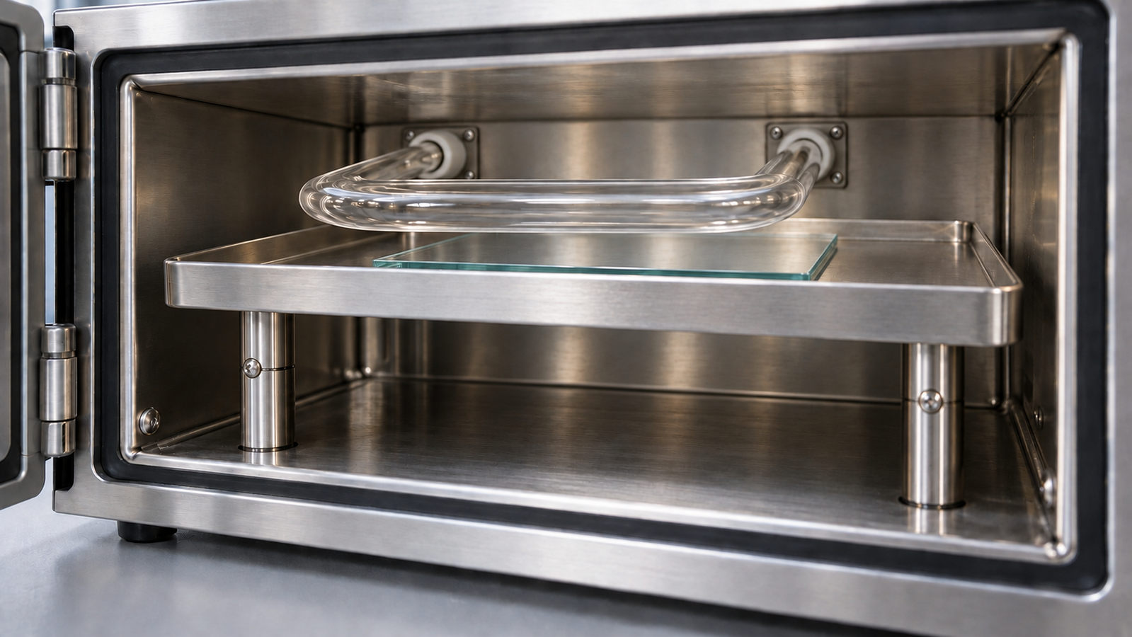
1. The short answer
UV ozone cleaning works because four agents act at once in the gap between lamp and sample. The table lists them, with where each comes from, what it does and where it acts:
| Agent | Where it comes from | What it does | Where it acts |
|---|---|---|---|
| 185 nm photons | Weaker mercury line, passed by the lamp envelope in ozone-producing lamps | Split O2 into oxygen atoms, which form ozone | In illuminated oxygen-containing gas; some light may also reach the sample |
| 254 nm photons | Main mercury line | Break ozone into O2 and atomic oxygen; excite or break many organic molecules | All the way to the sample surface |
| Ozone (O3) | Made by the 185 nm reaction; carried by diffusion and air movement | Oxidises contaminants directly; acts as the source of atomic oxygen at the surface | Throughout the chamber |
| Atomic oxygen (O) | Ozone photolysis at 254 nm; O2 photolysis at 185 nm | Attacks excited contaminant fragments, ending as CO2 and H2O | Only within a short distance of where it is made |
Mechanism as summarised in the UV/ozone cleaning reviews [1][2]. The relative importance of each path depends on lamp, gap, gas and contaminant.
The practical rules follow: preclean first, because UV-ozone only finishes thin organic films; put the sample close to the lamp; heat if the substrate allows; and measure the result with a water contact angle rather than trusting a fixed time. For where surface cleaning sits among the other steps before coating, see the pillar guide, Solution-Processed Thin Films: Choosing Spin, Dip, Slot-Die or Blade Coating.
2. What the lamp emits
UV-ozone cleaners use low-pressure mercury discharge lamps. At low pressure, mercury vapour emits most of its ultraviolet output in two lines: a strong line at 253.7 nm, usually rounded to 254 nm, and a weaker line at 184.9 nm, rounded to 185 nm. Whether the 185 nm line leaves the lamp depends on the envelope. Transmission depends on the quartz grade: ozone-producing envelopes pass 185 nm, while ozone-free envelopes suppress it, often by doping the quartz. The reviews stress that the wavelengths emitted are one of the main variables in UV/ozone cleaning [1][2]. A lamp without the 185 nm line still cleans, but more slowly, because it makes no ozone itself.
Photon energy explains why the two lines behave differently. The energy of a photon in electronvolts is about 1239.8 divided by the wavelength in nanometres:
| Line | Photon energy | Per mole of photons | Compared with the O=O bond (about 5.1 eV) |
|---|---|---|---|
| 184.9 nm | 6.71 eV | about 647 kJ/mol | Enough to split O2 |
| 253.7 nm | 4.89 eV | about 472 kJ/mol | Not enough to split O2; enough to split O3 |
Photon energies calculated from E = hc/λ. The O=O bond dissociation energy of about 5.1 eV (about 494 kJ/mol) is a textbook value; it corresponds to a threshold wavelength near 242 nm.
The 254 nm photon is below the threshold for O2, so it passes through clean air almost untouched. It is well above the energy needed to break the weak bond that holds the third oxygen atom in ozone, and many organic molecules absorb near 254 nm. Typical C–C and C–H bonds lie in the 3.5 to 4.5 eV range, so absorbed light can break them. Ultraviolet light alone can clean more slowly than combined UV/ozone treatment [2]. The large gain comes from combining it with the oxygen chemistry of the next section.
3. From oxygen to ozone to atomic oxygen
Three reactions do most of the work. Written in words, with the wavelength that drives each:
- Ozone production (185 nm). O2 + hν → O + O. Each oxygen atom then joins an O2 molecule in a collision with a third molecule M that carries away the excess energy: O + O2 + M → O3 + M.
- Ozone photolysis (254 nm). O3 + hν → O2 + O. At 254 nm most of the oxygen atoms are formed in an excited state, which is even more reactive than the ground-state atom.
- Oxidation of the contaminant. Contaminant molecules excited or broken by the ultraviolet light react with atomic oxygen and ozone. Step by step they become smaller, more oxidised fragments and finally CO2, H2O and other volatile products that desorb [1].
The cycle is self-sustaining: 185 nm light makes ozone, 254 nm light destroys it and in doing so releases atomic oxygen. The ozone level settles at a balance of production, photolysis, thermal decomposition, surface reaction and removal by the fan or exhaust; heat speeds the decomposition. The ACS Material guide Plasma Ozone Generation: Inside the DBD Ozonizer describes the same thermal fragility from the ozone-generator side.
How strongly each gas absorbs each line is set by its absorption cross section. Measured values show the contrast clearly:
| Absorber and wavelength | Cross section | What it means in practice |
|---|---|---|
| O2 at about 235 nm (continuum) | 3.8 × 10⁻²⁴ cm2 [5] | Air is practically transparent near 254 nm |
| O2 at about 198 nm | 1.07 × 10⁻²³ cm2 [5] | Absorption begins to rise |
| O2 at about 181 nm | 7.1 × 10⁻²² cm2 [5] | Continuum value only; not the effective absorption at 184.9 nm |
| O3 at 254 nm | about 1.1 × 10⁻¹⁷ cm2 [6] | Ozone absorbs 254 nm light millions of times more strongly than O2 absorbs near 235 nm |
O2 values from Ogawa’s continuum measurements; the O2 absorption at 184.9 nm itself lies in a banded region and depends on temperature and lamp line shape, so no single value is quoted. The ozone value is rounded from the recommended cross section at the 253.65 nm mercury line.
O2 absorbs the 185 nm line and initiates ozone formation along the illuminated gas path. How far it gets depends on the lamp spectrum and the length of the gas path, so some 185 nm light may still reach a sample a few centimetres away. Ozone is the main gas-phase absorber at 254 nm.
4. What actually reaches the surface
For a sample a few centimetres below the lamp, three things could arrive: photons, ozone and atomic oxygen.
254 nm photons
The loss of 254 nm light on the way down is governed by ozone absorption. By the Beer–Lambert law the transmitted fraction is T = exp(−σ·n·L), where σ is the ozone cross section, n the ozone number density and L the path length. Air at room temperature and atmospheric pressure contains about 2.46 × 10¹⁹ molecules per cm3, so 1 ppm of ozone is about 2.46 × 1013 cm−3. With σ taken as 1.1 × 10⁻¹⁷ cm2:
| Assumed ozone level in the gap | Transmission over 3.1 cm | Over 3.5 cm | Over 4.4 cm |
|---|---|---|---|
| 10 ppm | 99% | 99% | 99% |
| 100 ppm | 92% | 91% | 89% |
| 300 ppm | 78% | 75% | 70% |
| 1000 ppm | 43% | 39% | 30% |
Illustrative arithmetic. The ozone levels are assumptions chosen to show the trend, not measured concentrations in any instrument; real chambers have uneven ozone distributions and the lamp is not a point source. The path lengths are the illumination heights discussed in section 11.
At moderate ozone levels most of the 254 nm light reaches the sample, and light absorbed on the way still releases oxygen atoms. Higher ozone levels reduce transmission, so the fan setting is a process variable: record it and keep it fixed while developing a process.
Ozone
Ozone is stable enough to fill the chamber. By kinetic theory, at an assumed 100 ppm ozone molecules strike each cm2 of surface about 2 × 10¹⁹ times per second, but only a small fraction of these collisions react, so the collision rate does not tell you the cleaning rate. Ozone on its own oxidises many organics slowly; with ultraviolet light the combination is much faster than either alone [2].
Atomic oxygen
Atomic oxygen is short-lived in room-temperature air at atmospheric pressure. Excited atoms rapidly quench or react, and ground-state atoms rapidly form ozone. Atomic oxygen made near the lamp therefore does not travel intact across a centimetre-scale gap. Atomic oxygen involved in cleaning is generated near the surface, including by ozone photolysis at 254 nm and by O2 photolysis wherever 185 nm light remains.
5. Distance, time and temperature
Vig reports that, with the sample within a few millimetres of an ozone-producing lamp, properly precleaned surfaces can be made clean in less than one minute [1]. Cleaning in seconds to a minute is the short-gap, high-intensity limit. Benchtop cleaners hold the sample a few centimetres below the lamp for even illumination and easy loading, so cleaning takes minutes.
| Variable | Effect on cleaning rate | Why |
|---|---|---|
| Shorter lamp-to-sample gap | Faster | Higher irradiance; more ozone near the surface; less 254 nm absorption on the way |
| Ozone-producing lamp (185 nm passed) | Faster | Ozone generated from molecular oxygen in the chamber |
| Heated sample | Faster | Reaction and desorption speed up; volatile products leave sooner [1] |
| Thicker or inorganic-rich contamination | Slower or incomplete | More material to oxidise; non-volatile oxides stay behind |
| Poor precleaning | Slower or incomplete | Gross contamination must go first [2] |
| Strong air flow across the sample | Can be slower | Ozone is swept away before it is photolysed at the surface |
Qualitative trends from the cited reviews and from the photochemistry above; the magnitude of each effect depends on the instrument and the contaminant.
Time should be established, not copied. A simple way is a time series: clean identical precleaned samples for, say, 0, 2, 5, 10 and 20 minutes, measure the water contact angle on each immediately afterwards, and plot angle against time. The angle falls and then levels off. The first point on the plateau is a candidate endpoint, not proof that contamination has gone. Confirm it with the actual coating and, where needed, surface analysis. Longer exposure can still change the substrate surface (section 7).
Heating speeds up oxidation and desorption, but it also speeds up ozone decomposition, so the benefit levels off. Use moderate heating, set by the most fragile layer on the substrate rather than by the cleaning rate.
6. What it removes and what it does not
Vig and LeBus list the contaminants UV/ozone removed in their work: oils, greases, fluxes, skin oils and contamination adsorbed from the air. Their list includes silicone oils and greases, but with silicones the organic groups are oxidised and a silica-like layer can stay behind (table below). They list the variables as the types of contaminant, the precleaning, the wavelengths, the atmosphere, the distance from the lamp and the time [2]. The common thread is that the contamination must be organic, thin and oxidisable to volatile products.
| Contamination | Removed by UV-ozone? | Comment |
|---|---|---|
| Adsorbed airborne hydrocarbons | Yes | The classic target; returns slowly in air after cleaning |
| Skin oils, light oils, greases | Yes, if thin | Thick films need a solvent or detergent first |
| Silicones | Not reliably removed | Organic groups can oxidise while a non-volatile silica-like residue remains [7] |
| Photoresist and polymer residues | Slowly | Thin residues can be ashed; thick layers are better stripped first |
| Particles and dust | No | Not oxidisable to gas; remove by rinsing, ultrasonics or blowing with filtered gas |
| Salts, metals, ionic residues | No | Water removes soluble salts; metals and insoluble residues need a substrate-compatible cleaning method |
| Water marks | Organic part only | Dissolved minerals remain as a residue |
Summary of general behaviour; the first entries follow Vig and LeBus [2]. Results for a specific residue should be checked, not assumed.
That is why UV-ozone is placed at the end of a cleaning sequence. Detergent or solvent cleaning, often ultrasonic, removes particles and gross residues; UV-ozone then removes the last organic film, including solvent traces. Skipping the precleaning is a common reason UV-ozone seems not to work. The full sequence, and how long a clean surface stays clean, is the subject of Substrate Cleaning Protocol for Thin-Film Devices: Solvents, UV-Ozone, Plasma and Queue Time.
7. Effects on common substrates
UV-ozone is gentle compared with ion bombardment, but it is still an oxidising treatment. On some substrates the change in surface chemistry is the point; on others it is a side effect to control.
| Substrate | Main effect beyond cleaning | What to watch |
|---|---|---|
| Glass, fused silica, quartz | Very hydrophilic, high-energy surface | Recontamination from air; coat soon after cleaning |
| Silicon with native oxide | Organic-free oxide surface; oxide can thicken slightly | Matters only where interface oxide thickness is critical |
| ITO | Carbon removed; work function rises | Change in energy alignment with the next layer [4] |
| PDMS | Surface chemistry modified, not just cleaned [7] | Surface and subsurface chemistry change; validate dose and storage conditions |
| Other polymers (PET, PI, PEN) | Surface oxidation raises wettability | Prolonged exposure can degrade or roughen the surface |
| Metals such as Ag or Cu | Surface oxidation | Oxide can change contact resistance or optical behaviour |
General behaviour; the ITO entry follows Sugiyama et al. and the PDMS entry Efimenko et al. Effects depend on dose, temperature and the exact material.
The ITO case is the one most coating users meet. Sugiyama and co-workers measured ITO by photoemission after different cleaning methods. The work function was 4.5 eV after solvent cleaning and 4.75 eV after UV-ozone treatment, and fell to 4.3 eV after argon-ion sputtering. They concluded that removing surface carbon is the main reason for the rise after both UV-ozone and oxygen-plasma treatment [4]. For an organic or perovskite device built on ITO, the clean is therefore also an interface treatment. A related study tied the physical, chemical and morphological properties of treated ITO anodes to the performance of polymer light-emitting diodes [8]. How UV-ozone compares with oxygen plasma on ITO and glass is the subject of UV-Ozone vs Oxygen Plasma for ITO and Glass: Which Clean Before Coating?.
8. Checking that the clean worked
Clean oxide surfaces such as glass have a high surface energy, and water spreads on them. Even a thin layer of hydrocarbon lowers the surface energy and makes water bead up. That makes the water contact angle a sensitive, quick check of organic contamination on glass, and it is the basis of the standard test method ASTM C813 [9].
| Check | What it shows | Practical notes |
|---|---|---|
| Water contact angle (sessile drop) | Hydrophobic contamination on hydrophilic surfaces | Measure immediately after cleaning; use the same drop volume and the same water every time |
| Water-break test | Whether a water film stays continuous or breaks into patches | Quick and needs no instrument; qualitative |
| Test coating | Whether the actual ink wets and stays wetted | The most relevant check; slower |
| Surface analysis (for example XPS) | Carbon on the surface and its chemistry | Used to set up a process, not for routine checks |
The water-break and test-coating methods are general workshop practice; XPS was the method used by Sugiyama et al. [4].
Two cautions apply. First, a low water contact angle is not the same as good wetting by an ink, because inks have lower surface tensions than water. The wider story is in Why Your Ink Dewets: Surface Energy, Contact Angle and Wetting Before You Coat. Second, a clean surface readsorbs organics from the air, and the angle rises again over minutes to hours. Keep the queue time to coating short and consistent.
9. Ozone and UV safety
The two hazards are the ozone and the light. Ozone is a respiratory and eye irritant and a powerful oxidiser. In the NIOSH Pocket Guide, the NIOSH recommended exposure limit is a ceiling of 0.1 ppm (0.2 mg/m3), the OSHA permissible exposure limit is 0.1 ppm as a time-weighted average, and the IDLH value is 5 ppm [10]. Limits differ between countries and institutions, so follow your local rules. Smell adapts, so it is not a reliable monitor. Vig’s review also covers safety [1].
| Hazard | Control |
|---|---|
| Ozone escaping when the chamber is opened | After the lamp switches off, keep the chamber closed until the ozone has cleared, as the instrument manual and your local safety rules require |
| Ozone in the room during operation | Vent the exhaust to a fume hood or extraction line, or through an ozone destruction unit; check with an ozone monitor where exposure is possible |
| Short-wave UV on eyes and skin | Run only with the chamber closed and any interlocks working; never look at a lit lamp |
| Degradation of nearby materials | Keep rubber, some plastics and sensitive samples out of the chamber and exhaust path |
| Flammable solvent vapour from wet samples | Dry samples fully before loading |
Exposure limits from the NIOSH Pocket Guide [10]. The controls are general laboratory practice; your institution’s safety office sets the rules for your installation.
10. Setting up a first UV-ozone run
For a new substrate or contamination problem, steps 1–4 give a candidate process in an afternoon; step 5 confirms it:
- Preclean by detergent or solvent, rinse and dry with filtered nitrogen. Never load wet samples.
- Set the gap as short as the hardware and sample thickness allow, note it and keep it fixed.
- Choose a temperature the substrate and existing layers tolerate, or room temperature.
- Run a time series as in section 5, with extraction running, and measure the contact angle within minutes of unloading.
- Validate the candidate endpoint with the actual coating and any required surface analysis; keep the queue time short and fixed.
When a working clean fails, check precleaning, gap and queue time before the lamp; a repeated time series shows whether lamp ageing has moved the plateau.
11. Levon™ UV ozone cleaners
The table quotes the Levon™ UC100-SE and UC200-SE product pages. “Not stated” means the page does not give the value, not that the feature is absent.
| Specification | UC100-SE | UC200-SE |
|---|---|---|
| Lamp | 300 W U-shaped lamp; 185 nm + 254 nm | 300 W lamp; 185 nm + 254 nm |
| Lamp lifetime | ≥8000 h | ≥8000 h |
| Cleaning area | ≤8 in | ≤8 in |
| Lamp-to-sample height | 35 mm illumination height | 31–44 mm irradiation height (substrate thickness excluded), set by jacking |
| Sample lifting | Not stated | Stainless lift pins with external knob; 0–13 mm; minimum substrate for jacking 50 × 50 mm square or 50 mm round |
| Maximum substrate thickness | Not stated | 10 mm (customisable) |
| Heating | Not stated | 500 W hot plate; RT to 200 °C; 30–35 min to reach 200 °C |
| Fan | 5-level speed regulation | 5-gear speed regulation |
| Timer | Continuous cleaning time up to 99.99 h | Continuous cleaning time up to 99.99 h |
| Control and display | Integrated embedded control; LCD with text interaction | Independent control system; LCD dot-matrix display |
| Chamber | Pull-out chamber with damped self-closing; independent tray and lamp structures | Not stated |
| Power supply | Not stated | 200–230 V single phase; 800 W (220 V) |
| Dimensions | 330 × 423 × 312 mm; 19 kg | 360 × 500 × 300 mm |
| UV intensity at the sample | Not stated | Not stated |
| Ozone concentration | Not stated | Not stated |
| Exhaust connection or ozone destruction | Not stated | Not stated |
| Process gas or purge | Not stated | Not stated |
Specifications as published on the Levon™ UC100-SE and UC200-SE product pages on 22 October 2026. Both pages state a one-year product warranty and that external utilities, where required, are supplied by the user. The supplied configuration is confirmed in the quotation.
How this connects to the guide: both lamps pass the 185 nm line, so both make their own ozone (section 3). The 35 mm and 31–44 mm heights are the path lengths used in the table of section 4. The UC200-SE provides the two controls discussed in section 5: adjustable irradiation height and a hot plate. The pages list adjustable fan speeds but do not specify exhaust arrangements or ozone-clearance performance; confirm these for the supplied system.
12. Keep Exploring the Surface Preparation Knowledge Hub
Start here
- Solution-Processed Thin Films: Choosing Spin, Dip, Slot-Die or Blade Coating — the coating methods that a clean surface prepares for.
- Plasma Cleaning: How It Removes Contamination — the plasma route to the same goal.
- Plasma Surface Activation: Wettability and Adhesion — how treated surfaces gain wettability and adhesion.
- Plasma Ozone Generation: Inside the DBD Ozonizer — how ozone is made by discharge, and why heat destroys it.
Cleaning and activation guides
- UV-Ozone vs Oxygen Plasma for ITO and Glass: Which Clean Before Coating? — choosing between the two dry cleans.
- Benchtop Plasma Cleaners Compared: 25 kHz, 40 kHz and 13.56 MHz — what the drive frequency changes.
- Substrate Cleaning Protocol for Thin-Film Devices: Solvents, UV-Ozone, Plasma and Queue Time — the full sequence from detergent to coater.
- Why Your Ink Dewets: Surface Energy, Contact Angle and Wetting Before You Coat — reading contact angles and fixing dewetting.
Links will be added as each article is published.
Levon™ UV ozone and plasma cleaners
- UC100-SE UV Ozone Cleaner — 300 W 185/254 nm lamp, 35 mm illumination height, pull-out self-closing chamber.
- UC200-SE Heated UV Ozone Cleaner — 300 W 185/254 nm lamp, 31–44 mm adjustable height, hot plate to 200 °C.
- All Levon™ UV ozone cleaners — the UV ozone cleaner category page.
- All Levon™ plasma cleaners — the plasma cleaner category page.
Questions about a specific substrate, contamination or configuration can be sent through the contact form.
13. FAQ
Why does a UV-ozone cleaner need both 185 nm and 254 nm light?
The 185 nm light splits oxygen molecules and so makes ozone. The 254 nm light breaks that ozone into highly reactive atomic oxygen close to the surface and also excites the contaminant molecules. Together they clean much faster than either wavelength, or ozone alone, would.
How long should UV-ozone cleaning take?
It depends on the gap, the lamp, the temperature and the contamination, so establish it with a time series and a water contact angle check. With the sample a few millimetres from the lamp, precleaned surfaces can clean in under a minute; at the few-centimetre gaps of benchtop cleaners, expect minutes.
Can UV-ozone replace solvent cleaning?
No. UV-ozone removes thin organic films. Particles, salts and thick residues are not converted to gas and must be removed first by detergent, solvent and water cleaning. UV-ozone is the last step before coating, not the only one.
Does UV-ozone damage ITO?
It does not remove the ITO, but it changes the surface: removing carbon raises the work function, from 4.5 eV after solvent cleaning to 4.75 eV after UV-ozone in one photoemission study. That is often useful for devices but should be treated as part of the interface, kept consistent and not overextended.
Is the ozone from a UV-ozone cleaner dangerous?
Ozone is a respiratory irritant with occupational limits around 0.1 ppm. Run the cleaner closed with exhaust to extraction or an ozone destruction unit, let the ozone clear before opening, and follow the instrument manual and your institution’s safety rules.