
A benchtop plasma cleaner is often chosen by its drive frequency, 25 kHz, 40 kHz or 13.56 MHz. This guide explains what frequency changes, what it does not, and which other spec lines decide whether a cleaner suits the clean you run before coating a thin film.
In one paragraph: Frequency is real physics, but it does not on its own make one benchtop plasma cleaner gentler or better than another. For a clean before coating, choose on chamber fit, the gases you need, how repeatably you can set gas flow, power and time, and the operating pressure, and qualify both the surface condition and the downstream coating result [4]. Then coat promptly, because clean surfaces recontaminate in air and plasma-treated polymers recover [8][9].
1. What Drive Frequency Changes, and What It Does Not
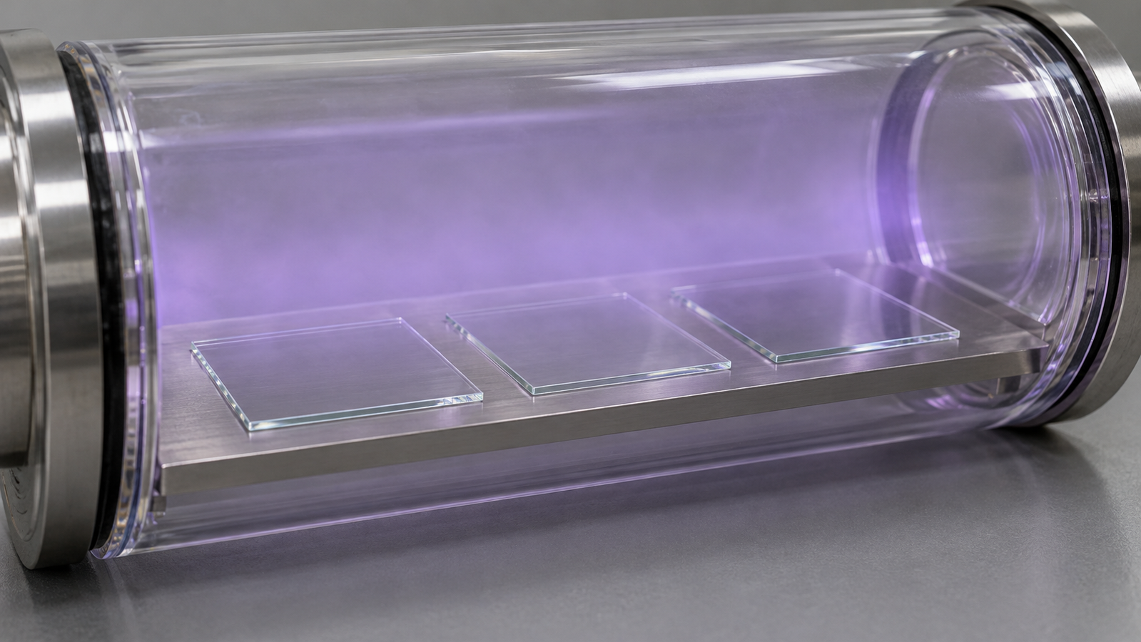
Benchtop plasma cleaners are usually sold by their drive frequency: a few tens of kilohertz, or 13.56 MHz. The number is real physics, but it is only one of several things that decide what reaches your substrate. This guide is about one decision: which benchtop plasma cleaner suits the clean you do before coating. That clean removes thin organic films, makes the surface wet well and is followed promptly by coating. The discharge physics is covered in depth in the plasma series; here it is summarised only as far as it affects that choice.
Frequency sets how the charged particles in the discharge respond to the applied field. Electrons are light and follow the field at both kilohertz and megahertz frequencies. Ions are far heavier. In the sheath, the thin boundary layer between the glow and any surface, the energy with which ions arrive depends on how the time an ion takes to cross the sheath compares with the period of the drive voltage [1][2]. When the period is long compared with that transit time, ions respond to the instantaneous sheath voltage; when it is short, they respond more to its average. The plasma series explains the consequences in RF vs Microwave vs Pulsed Plasma Sources: How to Choose and Plasma Frequency, Duty Cycle & Waveform: A Practical Tuning Guide.
What frequency does not decide on its own is whether one cleaner is “gentler” or “harsher” than another. The ion energy and the flux of reactive species at the surface also depend on electrode geometry, where the substrate sits relative to the glow, the gas and its pressure, and the power actually absorbed [1]. Two instruments at the same frequency can treat a surface quite differently, and two at different frequencies can produce similar results for a given task. A comparison by frequency alone is therefore incomplete.
2. Kilohertz vs 13.56 MHz in Brief
The three drive frequencies found on Levon™ benchtop plasma cleaners, 25 kHz, 40 kHz and 13.56 MHz, fall into two broad groups.
- Kilohertz drives (25 kHz and 40 kHz). The drive period is long. The plasma series notes that at kilohertz and pulsed timescales ions can respond substantially to the field, which is part of why the waveform matters in that regime (Plasma Frequency, Duty Cycle & Waveform: A Practical Tuning Guide).
- Radio frequency (13.56 MHz). This is the industrial, scientific and medical frequency most widely used for processing plasmas [1]. When ion transit takes much longer than an RF period, ions respond mainly to the time-averaged sheath field; frequency alone does not establish that regime [2]. RF systems normally include a matching network so that the generator delivers its power into the discharge rather than reflecting it back; Impedance Matching for Plasma Systems: Where Your Watts Actually Go explains why that matters.
For a pre-coating clean, the practical question is not which group is “better” but whether the instrument reproducibly delivers a treatment that removes the contamination and leaves the surface ready for the next layer. That depends on how well you can set and repeat pressure, gas flow, power and time, so the spec lines below are what decide the choice. For the types of discharge involved, see Corona vs Glow vs Arc vs DBD: How Plasma Discharges Differ; for what plasma does at a contaminated surface, see Plasma Cleaning Explained: How Plasma Removes Nanoscale Contamination.
3. The Spec Lines That Matter for a Pre-Coating Clean
Read a benchtop plasma cleaner’s specification line by line, asking what each value means for a repeatable clean.
Power and how it is set
Power ranges tell you the ceiling and the adjustment span. Note also whether a page gives a range that you set, a maximum, or both. More power is not automatically a better clean: plasma changes surface chemistry as well as removing contamination, and on polymers the different gas-phase treatments modify the surface in different ways [3]. The useful question is whether you can set a low enough power for fragile parts and repeat a chosen setting exactly.
Chamber fit
Confirm the usable treatment region, loading orientation, supports and clearances for your substrate or batch. Chamber dimensions and a stated substrate diameter do not alone establish that a substrate fits flat or receives uniform treatment.
Clarify what the published vacuum level means
The pages report “vacuum level” values of “<10 Pa” or “≤100 Pa” without defining their measurement conditions. Confirm whether these refer to pump-down or another condition, and obtain the supported operating-pressure range. Pressure affects how far species travel between collisions and how the glow fills the chamber [1], so ask how process pressure is set and read on the instrument you are considering, and what pump speed it is specified with.
Gas control and repeatability
Gas delivery comes in three common forms: a single gas path, float (variable-area) flowmeters that are read by eye, and mass flow controllers (MFCs) that meter and regulate flow electronically. MFCs give a set point you can record and repeat; float flowmeters depend on reading the float and on the gas and pressure they were calibrated for. Where a configuration lists two gas channels, confirm whether they support the intended gas combination and simultaneous mixing; channel count alone does not establish either. None of the Levon™ plasma cleaner pages names its process gases, so confirm with the supplier which gases are supported before planning an oxygen, argon or mixed-gas clean.
Time range and stabilisation
Confirm the treatment timer’s minimum, maximum, resolution and start condition. Include the published gas stabilisation time in throughput planning only after confirming how it fits into the operating cycle.
4. Judge the Clean by the Surface, Not the Setting
The “right” plasma clean is defined by the surface that leaves the chamber, not by the instrument setting. A few patterns from the literature help set expectations.
- Glass and oxides. A suitable oxidising plasma treatment can reduce organic contamination and improve wetting on compatible glass or oxide surfaces. ASTM C813 uses the water contact angle to detect hydrophobic contamination on glass [4], which makes it a practical check for that contamination.
- ITO. Oxygen plasma changes the indium tin oxide (ITO) surface as well as cleaning it; its work function and the performance of devices built on it depend on the treatment used [5][6][7]. If ITO is your anode, fix the treatment and coat promptly.
- Polymers. Plasma-treated polymers often lose part of their wettability over time as the surface reorganises, a process called hydrophobic recovery [8]. Plan coating soon after treatment, and test wetting on the day.
- Air exposure. Li and co-workers linked increasing water contact angle on supported graphene and graphite to airborne hydrocarbon adsorption [9]. The time between cleaning and coating is part of the process.
Use defined acceptance criteria rather than maximum power. Contact angle can track hydrophobic contamination on glass, but wetting alone does not establish particle removal, preserved surface chemistry or satisfactory coating performance. The wetting side of this is covered in Plasma Surface Activation: How It Improves Wettability & Adhesion, and Why Your Ink Dewets: Surface Energy, Contact Angle and Wetting Before You Coat examines how ink properties and surface condition together affect wetting.
Plasma is not the only dry clean. UV-ozone can operate in air at atmospheric pressure; confirm the selected instrument’s utilities and ozone-exhaust requirements. The trade-offs are compared in UV-Ozone vs Oxygen Plasma for ITO and Glass: Which Clean Before Coating?; the full sequence of solvents, dry clean and queue time follows in Substrate Cleaning Protocol for Thin-Film Devices: Solvents, UV-Ozone, Plasma and Queue Time.
5. A Selection Checklist
Before you compare models, write down the answers in the left-hand column. They turn a frequency comparison into a decision.
| Question | Why it matters | Where to look |
|---|---|---|
| Largest substrate and batch size | Sets the minimum chamber size and how parts are supported | Chamber dimensions; substrate size line |
| Which gases you need | Oxygen, argon and mixed-gas cleans need compatible gas paths | Gas control line; ask the supplier (not stated on the pages) |
| How repeatable the flow must be | Recorded MFC set points are easier to repeat than float readings | Gas control line |
| Lowest power you will use | Fragile layers and polymers need low, repeatable power | Power range and how it is adjusted |
| Treatment times | Short activation or long cleans | Time setting |
| Operating pressure | The published vacuum level does not define an operating-pressure range | Vacuum level, pump speed; ask how pressure is set |
| Acceptance tests | Checks defined surface and downstream acceptance criteria | Qualified wetting and coating tests; contact angle for hydrophobic contamination on glass [4] |
| Queue time to coating | Surfaces recontaminate and polymers recover | Your process plan [8][9] |
A checklist, not a ranking. Fill it in for your own substrates and process.
Frequency enters the decision mainly through the physics summarised above and through what each instrument offers around it: matching, chamber, gas control and timer. Matching a published method’s frequency does not remove the need to qualify its transfer to another instrument, chamber configuration or substrate.
6. Levon™ Plasma and UV-Ozone Cleaners
The tables quote the Levon™ product pages; “Not stated” means the page does not give the value.
| Specification | PT500 | PT13M | PT40K |
|---|---|---|---|
| Frequency | 25 kHz | 13.56 MHz, automatic matching | 40 kHz, automatic matching |
| Power | 0–500 W, adjustable | GE, SE: 0–300 W; BE: 0–200 W (maximum 300 W) | BE: 0–500 W (maximum 1,000 W); SE: 0–1,000 W |
| Chamber | Ø150 × 152 mm, aluminum alloy (larger sizes can be customized) | 226 × 126 × 224 mm, 6.4 L, aluminum alloy | 226 × 126 × 224 mm, 6.4 L, aluminum alloy |
| Vacuum level | ≤100 Pa | <10 Pa | <10 Pa |
| Gas control | Single gas path, 0.1–1 L/min | GE: dual MFC; BE: single float flowmeter; SE: dual float flowmeters | BE: single float flowmeter; SE: dual float flowmeters |
| Time setting | 1–200 s, continuously adjustable | GE, SE: 6,000 s; BE: 999 s | 300 s |
| Substrates | Not stated (chamber size above) | Under 8 inches; complex shapes | Up to 8 inches (200 mm) |
| Vacuum pump pumping speed | Not stated | GE, SE: 8 m3/h; BE: 4 m3/h | 4 m3/h |
| Gas stabilization time | Not stated | GE, SE: 30 s; BE: 40 s | 30 s |
| Process gases named | Not stated | Not stated | Not stated |
| Dimensions (W × D × H) | 452 × 386 × 225 mm; approx. 18 kg | 620 × 550 × 410 mm | 500 × 480 × 290 mm |
Specifications as published on the Levon™ plasma cleaner product pages on 22 October 2026. All three pages state that external utilities, where required, are supplied by the user. The supplied configuration is confirmed in the quotation.
How this connects to the guide: the PT500 runs at 25 kHz with a single gas path and a round chamber; the PT40K runs at 40 kHz with automatic matching; the PT13M runs at 13.56 MHz with automatic matching and, in its GE configuration, dual mass flow controllers. The questions in Section 5 decide between them more than the frequency alone: chamber fit, gas control, the power you need to set, and treatment time. Ask about supported gases and operating pressure before ordering. As an alternative to plasma, the UV-ozone cleaners below are compared in UV-Ozone vs Oxygen Plasma for ITO and Glass: Which Clean Before Coating?.
| Specification | UC100-SE | UC200-SE |
|---|---|---|
| Lamp | 300 W U-shaped lamp; 185 nm + 254 nm | 300 W lamp; 185 nm + 254 nm |
| Cleaning area | ≤8 in | ≤8 in |
| Published illumination / irradiation height | 35 mm illumination height | 31–44 mm irradiation height (substrate thickness excluded), set by jacking |
| Heating | Not stated | 500 W hot plate; RT to 200 °C |
| Continuous cleaning time (published) | 99.99 h | 99.99 h |
| Ozone concentration at the sample | Not stated | Not stated |
Specifications as published on the Levon™ UV-ozone cleaner product pages on 22 October 2026. The supplied configuration is confirmed in the quotation.
7. Keep Exploring the Surface Preparation Knowledge Hub
Start here
- Solution-Processed Thin Films: Choosing Spin, Dip, Slot-Die or Blade Coating — the coating methods this surface preparation serves
- UV-Ozone Cleaning Explained: 185 nm, 254 nm and What Reaches the Surface — how UV-ozone cleaning works
- UV-Ozone vs Oxygen Plasma for ITO and Glass: Which Clean Before Coating? — the two dry cleans compared for ITO and glass
Plasma physics behind the spec sheet
- RF vs Microwave vs Pulsed Plasma Sources: How to Choose — how source type changes the discharge
- Plasma Frequency, Duty Cycle & Waveform: A Practical Tuning Guide — frequency, duty cycle and waveform
- Impedance Matching for Plasma Systems: Where Your Watts Actually Go — why matching decides delivered power
- Plasma Cleaning Explained: How Plasma Removes Nanoscale Contamination — what plasma removes from a surface
- Plasma Surface Activation: How It Improves Wettability & Adhesion — activation, wetting and adhesion
- Substrate Cleaning Protocol for Thin-Film Devices: Solvents, UV-Ozone, Plasma and Queue Time — the full pre-coating cleaning sequence
- Why Your Ink Dewets: Surface Energy, Contact Angle and Wetting Before You Coat — surface energy and wetting before you coat
Links will be added as each article is published.
Equipment
- PT500 Plasma Cleaner — 25 kHz, 0–500 W, Ø150 × 152 mm chamber
- PT40K Plasma Cleaner — 40 kHz with automatic matching, 6.4 L chamber
- PT13M RF Plasma Cleaner — 13.56 MHz with automatic matching, 6.4 L chamber
- Levon™ Plasma Cleaners — all plasma cleaners
- Levon™ UV-Ozone Cleaners — the alternative to plasma cleaning
Questions about a specific cleaner, its gases or operating pressure can be sent through the contact form.
8. FAQ
Is a 13.56 MHz plasma cleaner better than a 40 kHz one?
Not in general. Frequency changes how ions in the sheath respond to the field [2], but the treatment also depends on electrode design, gas, pressure, power and time [1]. Choose on chamber fit, gas control and repeatability, then qualify the surface and coating results.
Is a kilohertz plasma gentler on delicate films?
Frequency alone does not decide this. The ion energy and species flux at the surface depend on the whole set-up. For fragile layers, qualify the treatment against both its intended endpoint and retention of the layer properties you need.
What gases do the Levon plasma cleaners use?
None of the three product pages names its process gases. Ask the supplier which gases each configuration supports before planning an oxygen, argon or mixed-gas clean.
Does the vacuum level on the spec sheet equal the process pressure?
Not necessarily. The pages do not define the conditions of the published vacuum-level values. Confirm their meaning, the supported operating-pressure range, and how pressure is measured and controlled.
How do I know the plasma clean worked?
Use qualified surface and coating tests. Contact angle can monitor hydrophobic contamination on glass [4], but is not a universal cleanliness or device-performance test. Coat promptly, because airborne hydrocarbons adsorb on clean surfaces, as shown for graphene and graphite [9], and plasma-treated polymers recover [8].