
A graphene oxide dispersion that should end up as a thin, even layer on a 25 mm glass square. A perovskite precursor that works on small spin-coated pieces and now has to cover 100 × 100 mm. A sol-gel coating for both faces of a microscope slide. All three start as a liquid and end as a solid film, and each could in principle be spun, dipped, slot-die coated or bladed. In practice each job suits one or two of those methods, because the four methods meter the liquid in different ways and accept different substrates. This guide gives the short answer first, then a selector and three worked cases, then the physics behind them, and finally the Levon™ instruments from ACS Material for each step, using only the specifications published on their product pages.
In one paragraph: choose the method by what meters the wet film and by the shape of the substrate. Spin coating thins a puddle by rotation; it suits wafers and small pieces and throws most of the ink away. Dip coating sets the film by withdrawal speed, drainage and evaporation; it coats both faces and needs a bath. Slot-die coating pumps a measured flow through a slot onto a moving substrate, so the average wet thickness follows from a mass balance — but only inside the window of speed, gap and flow where the coating bead is stable. Blade or rod coating spreads a bead through a gap or a wire-wound rod; the gap gives only a starting estimate, so the film is calibrated on the ink. It handles pastes and flexible sheets. Around any of them sits the same workflow: clean and activate, coat, bake or anneal, pattern if needed, and measure.
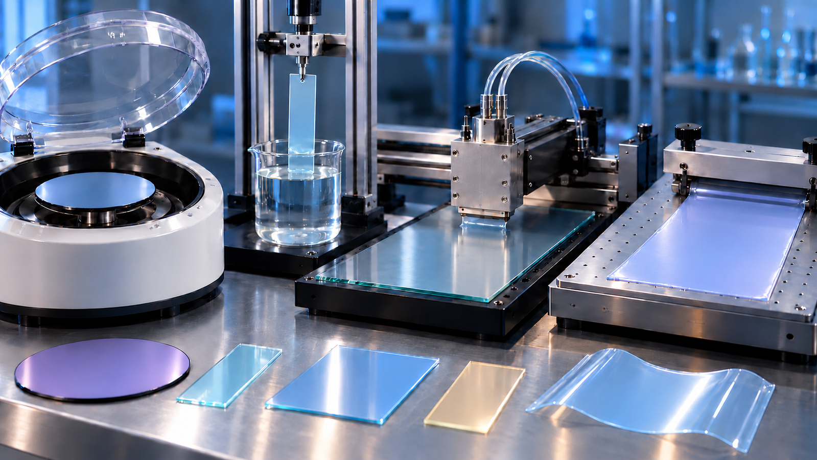
1. The short answer: four methods compared
The four methods differ in one physical point: what decides how much liquid stays on the substrate. In spin and dip coating the liquid is in excess and the film is what the flow leaves behind, so thickness follows from viscosity, speed and evaporation and is found with a speed series on the ink. In slot-die coating a pump meters the flow, so the average wet thickness follows from flow rate, width and speed — provided the coating is stable at those settings. In blade coating the gap limits the liquid, but the gap is only a starting estimate: the real film depends on the blade geometry, the ink bead, the speed and the ink's flow behaviour, and is calibrated in trial runs.
| Spin coating | Dip coating | Slot-die coating | Blade / rod (film applicator) | |
|---|---|---|---|---|
| What meters the wet film | Rotation thins the puddle; evaporation freezes it | Withdrawal speed against drainage and evaporation | Pump flow rate, coating width and speed (mass balance), inside a stable coating window | Blade gap or rod wire as a starting estimate; calibrated on the ink |
| How thickness is set in practice | Speed series and ink concentration | Withdrawal-speed series; two regimes | Calculated average, then trial runs for a defect-free window | Gap, speed and temperature series |
| Ink use | Most of the dispensed liquid leaves the substrate | Needs a bath deeper than the coated length | Close to all pumped ink ends up in the film | Only the bead in front of the blade is used |
| Natural substrate | Round wafers and small pieces | Plates, slides, pieces; both faces coated | Flat plates and sheets, larger than a few cm | Plates and flexible sheets on a vacuum panel |
| Typical weak point | Thick edge on non-round substrates; ink waste | Coats the back face; needs volume | Start and stop of the stripe; staying inside the window | Edges; very thin films need dilute inks |
A quick rule: a small piece or a wafer and a few millilitres of ink point to spin coating; both faces, or many repeated layers from a bath, point to dip coating; a plate of 100 mm or more and a need to save ink point to slot-die or blade coating, and pastes always point to a blade or rod. The selector below applies these rules to your sample and adds the equipment check.
2. Coating method selector
The selector checks spin, dip, slot-die and blade coating against your substrate, ink, thickness target, coated faces, heating (with the temperature, if you enter one), glovebox use and throughput. For each method it sorts the Levon™ models by whether their published specifications cover your answers, leave a point marked Confirm (not stated on the page, or not verified), offer a Custom option, or fall outside, and a single-model check says whether any one model meets every requirement you entered. The same labels carry into the inquiry summary. Hot plates are checked configuration by configuration. The second tab covers cleaning, baking and patterning for the same substrate; the third turns your answers into a plain-text summary for an inquiry, and is disabled while any input is invalid. It does not predict thickness, and where a product page does not state a limit, it says so.
3. Three worked selection cases
Each case runs from the need to the method, the equipment, the calibration and the post-treatment. Literature results are what the cited authors reported under their own conditions; they are not recipes and not performance figures for any Levon™ instrument. Every equipment point marked Confirm belongs in the inquiry; the selector and its inquiry summary use the same label.
Case A: a graphene oxide film on a 25 mm glass square
- Need. A thin, even GO film on one face of a 25 × 25 mm glass piece, from a water dispersion, later reduced.
- Method. Spin coating. The piece is small, only one face is wanted and a few millilitres of ink are enough. Dip coating would coat both faces; slot-die and blade coating need a run-up longer than the piece. Becerril and co-workers compared spin coating, drop casting and solvent-induced precipitation for GO and found spin coating gave the most uniform, though thinner, films.1
- Equipment. The EZ4-S, EZ6-S and AC100-S all list 10 mm, 25 mm and 2-inch chucks. Confirm the chuck that holds a square 25 mm piece securely; its diagonal is about 35 mm. If the substrate must be hot while it spins, the IC5000-S jaw chuck takes 10 to 35 mm square or round substrates on a table heated to 150 °C.
- Surface. A water ink has to wet the glass. Becerril's group used piranha-cleaned glass and quartz with an aminosilane (APTES) layer.1 UV-ozone (UC100-SE) or plasma are other ways to activate a surface; a contact-angle check helps screen the wetting condition, and the final choice also weighs the chemistry of the surface, possible damage and the actual film.
- Calibration. Fix the spin program and run a GO concentration series; how strongly concentration and speed each move the film on this ink is measured, not assumed (section 4). Measure each film across a step with a profilometer or AFM, as the cited study did.1 ACS Material single-layer GO dispersions are listed at 5 or 10 mg/mL; the dilution that suits your thickness comes out of that series.
- Post-treatment. Drying and lower-temperature steps fit on a hot plate such as the HP5 (150 × 150 mm, to 300 °C). The most conductive films in the cited study came from thermal graphitization at 1100 °C under vacuum in a tube furnace,1 which is beyond any hot plate (the highest Levon™ plate, the HP100-HT, reaches 600 °C). The degree of reduction reached at your temperature has to be measured.
Case B: a 100 × 100 mm perovskite layer, toward scale-up
- Need. A perovskite absorber on 100 × 100 mm coated glass, today by spin coating, with a route to a scalable method; the precursor and the finished film are sensitive to moisture.
- Method, now. Spin coating still works at this size, but the corners collect liquid. The AC200 configurations handle fragments to 8-inch wafers and can be recessed into a glovebox; the square's diagonal of about 141 mm is within that on paper. Confirm the tray or chuck for a 100 mm square (the AC200-PE lists standard vacuum trays up to 6-inch diameter). For heated spin coating, the IC8000-S heats to 200 °C and takes glass pieces and 6-inch wafers; its page does not state glovebox use.
- Method, scale-up. Blade and slot-die coating are the routes the literature has taken. Deng and co-workers doctor-bladed methylammonium lead iodide films with the substrate held hot during coating; in their study 125 °C gave continuous films and 100 °C gave pinholes, and blading used 10 to 20 µL of precursor per 2.25 cm2 against 50 to 100 µL for spin coating.2 Hwang and co-workers printed every layer of their perovskite cells except the electrodes by slot-die coating, using a sequential deposition of the perovskite and a nitrogen gas stream to dry the wet film, and demonstrated the process in roll-to-roll coating.3
- Equipment. The PF200-H page publishes a heated panel from room temperature to 200 °C, an A4 vacuum area that holds the plate and a 250 mm stroke, and shows an air knife configuration (angle −45° to 45°, 10 to 35 mm above the substrate). For the PF200-H, Confirm the effective coating width, glovebox use and the supplied configuration in the quotation. The SD200 takes substrates up to 200 × 200 mm and 0.05 to 10 mm thick, with a 0 to 1000 µL/s syringe pump. For the SD200, Confirm the slot-die head width, whether a heated platform is available, and glovebox use; its page states none of them.
- Calibration. For the blade, a series in gap, speed and substrate temperature; for the slot die, the flow-and-speed window in which the stripe is continuous (section 4). Check thickness at several points across the plate, not only in the centre.
- Post-treatment. Anneal on a plate larger than the substrate: the HP5 (150 × 150 mm, recessed for glovebox use), the HP10 (220 × 220 mm) or the HP100-PE (220 × 220 mm). Outside a glovebox, the HP100-SA and HP100-PA bake in a nitrogen-filled chamber; their 0.04 to 0.4 MPa figure is a supply pressure, not an oxygen or moisture level at the film.
Case C: a sol-gel coating on both faces of a 75 × 25 mm slide
- Need. An oxide sol-gel film on both faces of a 75 × 25 mm glass slide about 1 mm thick, possibly several layers.
- Method. Dip coating. One withdrawal coats both faces, and sol-gel is the chemistry the method was developed around.4
- Equipment. The DP100-BE takes substrates up to 100 × 100 × 5 mm with a 0 to 100 mm lift stroke, 0.1 to 600 mm/min and 1 to 999 repeat cycles, and its compact structure (227 × 350 × 416 mm) is designed for placement in a glovebox. Confirm the clamp and that the bath is deeper than the 75 mm coated length. For alternating baths, the DP150-DR carries six 300 mL beakers. The DP100-BE-H adds a base heated to 120 °C; the page states the base temperature, not the bath temperature.
- Calibration. Run a withdrawal-speed series wide enough to show both regimes: at low speed, evaporation at the meniscus thickens the film as speed falls; at higher speed, viscous drag thickens it as speed rises (section 4).5 Build thicker coatings from several thin layers with drying in between, because thick single sol-gel layers tend to crack.
- Post-treatment. The firing temperature is set by the chemistry, not by the coater. On the published plate dimensions, a 75 × 25 mm slide lies within the plate of the HP5 (150 × 150 mm), the HP10 and HP100-PE (220 × 220 mm), the HP100-HT (215 × 215 mm) and the HP200-SE and HP200-PE (340 × 340 mm); of these, the HP10 (400 °C configuration) and the HP100-HT (600 °C) cover higher temperatures. The HP100-SE page states substrates below 8 inches without a plate size, and the nitrogen-filled HP100-SA, HP100-PA and HP200-SA pages give no plate size, so for those the fit is marked Confirm, not ruled out. Temperature, how a film coated on both faces is supported, and lift-pin or fixture fit are separate checks for each model. Because both faces are coated, a slide lying flat touches the plate with one film; proximity baking on lift pins or a stand-off holder avoids that. Confirm lift-pin support for a 25 mm wide slide (the HP100-PE page gives lift-pin use for substrates larger than 40 mm in diameter).
4. What sets the film: the essential physics
The relations below explain the rules of thumb used above. Each holds only under its stated assumptions, and none replaces a calibration series on your own ink. The full derivations belong to the dedicated articles in the knowledge hub.
Spin coating: the ink sets the thickness more than the motor does
For a Newtonian liquid on a flat rotating disc, centrifugal force drives the liquid outward against viscous drag, and the film thins evenly across the disc.6 Real inks also lose solvent while they spin. Meyerhofer combined flow with a uniform evaporation rate and found that the final thickness of photoresist films scales as f−2/3 · ν01/3 · e1/3, where f is the spin speed, ν0 the initial viscosity and e the evaporation rate; because e itself grows as f1/2, thickness falls as the inverse square root of spin speed.7,8
assumptions: Newtonian flow until the film sets, uniform evaporation, flat round substrate
1,000 → 4,000 rpm: thickness falls by √4 = 2×
Real inks, especially dispersions and fast-drying solvents, depart from the ideal exponent, so the exponent and prefactor for your ink come from a speed series. In that ideal model, for example, a fourfold increase in speed halves the film; for a real ink, how much speed, concentration and viscosity each move the film is measured with a speed series and a concentration series, not assumed. The axisymmetric result applies to round substrates; on a square, liquid collects at the corners.
Dip coating: two regimes
When a plate is pulled out of a bath, a film is dragged up with it while gravity and surface tension pull liquid back. At moderate to high withdrawal speed this viscous-drag (draining) regime is described for a Newtonian liquid at low capillary number by the Landau–Levich relation, which Brinker and co-workers used as the starting point for sol-gel dip coating.4
assumptions: Newtonian liquid, capillary number ηU/γ « 1, draining regime, negligible evaporation during entrainment
example: η = 1.2 mPa·s, γ = 22 mN/m, ρ = 790 kg/m³ (ethanol-like), U = 100 mm/min
→ capillary number ≈ 9×10⁻⁵, hwet ≈ 3.2 µm
Here thickness rises with speed as U2/3. At very low speed a different mechanism takes over: the capillary (evaporation) regime, in which solvent evaporates at the meniscus faster than the film drains and solids are fed to the drying line, so the film becomes thicker as the speed falls, roughly as 1/U. Between the two regimes the thickness passes through a minimum.5 The Landau–Levich number is therefore not a prediction at low speed, and a withdrawal-speed series is the quickest way to find which regime an ink is in.
Slot-die coating: a mass balance inside a coating window
A slot die is fed by a pump, and at steady state everything pumped is laid down, so the average wet thickness is the volume flow divided by the coated width and the coating speed. That mass balance says nothing about whether the film is defect-free. The coating window is the range of speed, gap and flow in which the bead between die lips and substrate is stable; outside it the film breaks into ribbing, rivulets or air entrainment, the edges and the start and stop of the stripe misbehave, and very thin wet films sit close to the low-flow limit.9
example (coating width assumed, not a published Levon™ value): hwet = 10 µm, W = 150 mm, U = 10 mm/s
→ Q = 0.010 mm × 150 mm × 10 mm/s = 15 mm³/s = 15 µL/s
The same arithmetic shows how little ink a pre-metered method needs: 10 µm of wet film over 200 × 200 mm is 0.4 mL, plus what stays in the lines and the die.
Blade and rod coating: the gap is a starting estimate
A blade held at a fixed gap above a moving substrate drags liquid through the gap. If no pressure pushes liquid through the gap and the liquid is Newtonian, the drag flow carries a layer about half the gap thick. Real conditions move the result away from that estimate: the height of the ink bead in front of the blade, the blade's shape and angle, the speed and the ink's shear thinning or yield stress all change it, so the gap is set from the estimate and then calibrated with the ink. On a wire-wound (Meyer) rod the grooves between the wires meter the liquid: Hu and co-workers coated silver nanowire ink on PET with wet films of 4 to 60 µm, set by the wire diameter and spacing.10 Blade, rod and slot-die coating are also the laboratory forms of the roll-to-roll methods used for large-area devices.11
example: gap g = 100 µm → about 50 µm wet before calibration
From wet film to dry film
φs = solids volume fraction of the ink; c = solids mass concentration; ρs = density of the dried solid; P = porosity of the dry film
assumptions: all solids stay in the coated area (no edge flow or run-off)
example (assumed values): hwet = 10 µm, c = 5 mg/mL, ρs = 2 g/cm³
→ dense film (P = 0): 10 µm × 0.005 ÷ 2 = 25 nm; with P = 0.3: about 36 nm
The density of a dried nanosheet or nanowire film and its porosity are rarely known in advance, so the relation is best used backwards: measure the dry thickness for one wet thickness and infer the effective factor for that ink.
5. Substrate, ink and the steps around the coater
Substrates
Round wafers are what spin coaters are built around. The published limits are a 4-inch maximum recommended diameter for the EZ4-S, fragments to 8-inch wafers for the AC200 configurations, and fragments under 1 cm to 12-inch (300 mm) wafers for the AC300-S-CTM and AC300-S-EN; anything larger is a custom request. The EZ6-S and AC100-S pages list their chucks but not a largest substrate. Plates and slides spin with thick corners; the spin coater pages state round sizes, so for a square the diagonal is the number to compare and the fixture is the point to confirm. Plates are the natural format for slot-die coating (SD200 and SD300: 200 × 200 or 300 × 300 mm, 0.05 to 10 mm thick) and for film applicators (PF200-H: 380 × 210 mm panel, A4 vacuum area; PF400: 540 × 345 mm panel, optional A4 or A3 vacuum area). Small pieces are spun on a small chuck or dipped in a clamp. Flexible sheets are held flat on a vacuum panel and bladed, rod coated or slot-die coated; spinning them needs a rigid carrier.
Inks: three nanomaterial examples
Three nanomaterials that ACS Material supplies show how published work has matched ink and method. They are examples of what the cited studies did, not recipes for the products linked.
Graphene oxide. Spin coating of aqueous GO onto quartz is covered in Case A.1 Eda and co-workers made large-area ultrathin reduced GO films by vacuum filtration and transfer, a route outside the four methods here.12 See the graphene oxide products and the graphene oxide guide.
Silver nanowires. Nanowire networks are usually rod, blade or slot-die coated, which lay the wires down without the radial flow of spinning. In the rod-coating study cited above, the coated PET reached 20 Ω/sq at about 80 % specular transmittance after drying, and the authors noted that the process scales to slot-die and gravure coating.10 ACS Material silver nanowires are supplied at a standard 20 mg/ml in ethanol, isopropyl alcohol or water; see also silver nanowire as an ITO alternative and transparent conductive films.
MXene. Dillon and co-workers spincast delaminated Ti3C2 from aqueous solution into optical-quality films with a conductivity of 6,500 S/cm and attributed it partly to the coplanar alignment spincasting gives.13 Hantanasirisakul and co-workers spray coated 5 to 70 nm transparent films.14 Zhang and co-workers blade coated large, liquid-crystalline flakes into free-standing aligned films, about 15,100 S/cm at 214 nm thickness and a tensile strength near 570 MPa at 940 nm.15 These studies used delaminated colloids; the multilayer Ti3C2Tx nanoflakes are supplied as a powder. The MXene series lists the available forms.
Photoresists, sol-gels and pastes. Photoresists are formulated for spin coating, and their data sheets give thickness against spin speed. Sol-gel precursors are the classic dip-coating chemistry and spin well too. Pastes and slurries that do not flow under rotation or drain on withdrawal belong on a blade or rod.
Clean and activate
Water and alcohol inks bead up on surfaces carrying organic residue. UV-ozone cleaning uses a lamp whose 185 nm line forms ozone from oxygen and whose 254 nm line is absorbed by ozone and by many organic contaminants, producing atomic oxygen that oxidises the residue; Vig's review notes that surfaces within a few millimetres of the lamp can be cleaned in under a minute.16 Low-pressure plasma does a similar job with ions and radicals. Surface treatment also changes properties: on indium tin oxide, the work function measured by photoemission depends on the cleaning method.17 The plasma surface activation guide covers wettability and adhesion.
Heat, glovebox and nitrogen
Heating while coating. The heated Levon™ coaters are the IC5000-S (spin table to 150 °C, 10 to 35 mm square or round pieces), the IC8000-S (spin table to 200 °C, glass pieces to 6-inch wafers), the DP100-BE-H (heated base to 120 °C) and the PF200-H and PF400-H film applicators (heated panel to 200 °C). These are set-point ranges; the temperature at the film surface is not published. The slot-die coater pages do not state a heated platform.
Inside a glovebox. Product pages state glovebox use for the AC200 configurations (recessed installation), the EZ4-S (glovebox-compatible design), the DP100-BE and DP100-BE-H (compact structure for placement in a glovebox, 227 × 350 × 416 mm), and the HP5, HP6 and HP10 hot plates. For other models the page does not say; in every case the box's antechamber and internal height decide.
Nitrogen-filled hot plates. The HP100-SA and HP100-PA and HP200-SA bake in a nitrogen-filled chamber with a stated nitrogen input requirement of 0.04 to 0.4 MPa. That is the supply pressure the instrument needs, not a flow rate and not an oxygen level at the sample, which the pages do not publish.
Pattern
For photoresist, the film is soft baked, exposed through a mask and developed. The MA200-BE mask aligner (365 nm, 8-inch exposure area, 0.1 to 3 mm working thickness) and the DM200-SE spin developer (fragments to 200 mm, 3 channels including one rinse and one nitrogen drying) cover the equipment chain. Chemistry is a separate question: resist, dose and developer come from the resist data sheet, and the equipment pages do not list compatible developers. Compatibility with a specific chemistry, for example an SU-8 developer, is not stated and has not been verified; a PTFE-lined chamber describes a material, not a compatibility list.
Measure
Films from tens of nanometres to a few micrometres on glass or silicon are measured optically or mechanically. Spectroscopic ellipsometry fits the change in polarisation of reflected light with an optical model and gives thickness and optical constants, down to a few nanometres when the model is right.18 Reflectometry fits interference fringes and is fast for transparent films thick enough to show them. Stylus profilometry or AFM measures a step in the film, needs no optical model and works on opaque films such as dense nanowire or MXene layers. Hall-effect and eddy-current gauges such as the MetriTec™ coating thickness gauge measure coatings on ferromagnetic or non-magnetic metal substrates, in micrometres; they are not a tool for nanometre films on glass or silicon.
6. Reading a data sheet
- Maximum spin speed is a hardware limit. It says how fast the motor turns without load, not how thin a film it will make. In the ideal model thickness falls only as the inverse square root of speed; for a real ink, speed and concentration are calibrated together.
- Uniformity tables belong to their conditions and their configuration. On the EZ6-S, ±0.53 % within wafer was measured on 4-inch wafers with AZ1500 (20 cP) at 1350 nm, and ±1.20 % on 6-inch wafers with SPR220-4.5 (123 cP) at 4400 nm; the two rows describe different resists and should not be merged. On the AC200, uniformity data are published for the S-PP, SE and PE configurations, not for the SE-PLUS, and the four-channel automatic dispensing ports are stated for the S-PP, SE and PE. These are published test results and do not transfer to a nanowire or flake dispersion.
- No spin recipe, no curve. The uniformity tables do not state the spin speed used, so they cannot be used to fit thickness against rpm. The resist data sheet is the source for that.
- Hot-plate uniformity values cannot rank the plates. The pages list, for example, ≤±2 % (HP5), ≤1 % (HP6), ≤±1.5 % (HP100-SE), ≤1 % from RT to 300 °C (HP100-PE), ≤±1 % to 200 °C (HP200-SE and HP200-PE) and ≤±4 % (HP100-HT). The measurement points, the reference temperature and what the percentage is taken of are not stated, and may differ between pages, so these values cannot be used to decide which plate is more uniform, nor converted into a temperature tolerance at your sample.
- Configurations are not interchangeable. The HP100-SE comes in 300 °C and 400 °C configurations and the HP100-PE reaches 300 °C; the 220 × 220 mm plate is stated for the HP100-PE, while the HP100-SE page states substrates below 8-inch. The HP10 has 300 °C and 400 °C configurations. Name the configuration in an inquiry.
- Nominal sizes are nominal. A 12-inch wafer is 300 mm; the AC300 pages state standard wafers up to 12 inches (300 mm) and offer custom solutions for larger substrates.
- What a page does not state. The slot-die pages do not give a die width or a heated platform, and the EZ6-S and AC100-S pages do not give a largest substrate. Those points belong in the inquiry, not in an assumption.
7. Levon™ equipment and your inquiry
The table keeps only the specifications that decide a selection; each product page has the full data.
| Step | Model or configuration | Deciding published specifications |
|---|---|---|
| Clean / activate | UC100-SE, UC200-SE | UV-ozone, 185 + 254 nm, cleaning area ≤8-inch; UC200-SE heated to 200 °C |
| Clean / activate | PT500, PT13M, PT40K | Plasma at 25 kHz (Ø150 × 152 mm chamber), 13.56 MHz (under 8-inch) and 40 kHz (up to 8-inch) |
| Spin coat | EZ4-S / EZ4-S-PP, EZ6-S, AC100-S | 4-inch maximum recommended, glovebox-compatible; chucks 10 mm, 25 mm, 2-inch (largest substrate not stated for EZ6-S and AC100-S) |
| Spin coat | AC200 (S-PP, SE, PE, SE-PLUS), AC300-S-CTM, AC300-S-EN | Fragments to 8-inch, recessed glovebox installation; fragments to 12-inch (300 mm) |
| Spin coat, heated | IC5000-S, IC8000-S | 10–35 mm square or round, to 150 °C; glass pieces to 6-inch wafers, to 200 °C |
| Dip coat | DP100-BE, DP100-BE-H, DP150-DR | ≤100 × 100 × 5 mm, stroke 0–100 mm, for glovebox placement (BE-H: heated base to 120 °C); ≤150 × 150 × 5 mm, six 300 mL beakers |
| Slot-die coat | SD200, SD300 | 200 × 200 or 300 × 300 mm, 0.05–10 mm thick; pump 0–1000 µL/s; head width not stated |
| Blade / rod coat | PF200-H, PF400, PF400-H | A4 vacuum area, 250 mm stroke, heated to 200 °C; A4/A3 vacuum area, 420 mm stroke (PF400-H heated to 200 °C) |
| Bake / anneal | HP5, HP6, HP10 (300 or 400 °C configuration) | 150 × 150 mm to 300 °C; Ø170 mm vacuum plate for wafers to 6-inch, to 250 °C; 220 × 220 mm to 300 or 400 °C; all for glovebox use |
| Bake / anneal | HP100-SE (300 or 400 °C configuration), HP100-PE, HP200-SE / HP200-PE, HP100-HT / HP100-HT-CTM | Substrates below 8-inch; 220 × 220 mm to 300 °C; 340 × 340 mm to 300 °C; 215 × 215 mm to 600 °C |
| Bake, nitrogen | HP100-SA, HP100-PA, HP200-SA | Nitrogen-filled, to 300 °C; nitrogen input 0.04–0.4 MPa (supply pressure); plate size not stated in the specification table |
| Pattern | MA200-BE, DM200-SE | 365 nm, 8-inch exposure area; spin developer for fragments to 200 mm, 3 channels including one rinse and one nitrogen drying |
Values from the Levon™ product pages as listed on 22 October 2026. The full range, including heat sealers and vapor deposition, is on the Levon™ equipment page.
Before you request a quote
- Model and configuration: for example AC200-SE or AC200-PE, HP100-SE in the 300 or 400 °C configuration, HP10 in the 300 or 400 °C configuration, PF400 or PF400-H.
- Substrate: shape, size, thickness, and whether fragments must be handled; for spin coaters, the chucks or trays you need.
- Ink: solvent, viscosity if known, solids content, and whether it is a dispersion of flakes or wires.
- Film: target thickness, the area that must be uniform, and whether both faces may be coated.
- Conditions: heating during coating and the temperature, bake temperature and atmosphere, glovebox internal dimensions and antechamber size.
- Utilities: vacuum supply (several spin coater pages state 0.06–0.09 MPa with a flow above 15 L/min), nitrogen for the SA and PA hot plates, and mains voltage.
- Points the page leaves open: slot-die head width and heating, largest substrate on the EZ6-S or AC100-S, and anything the selector marked Confirm or Custom.
The selector's third tab writes these answers into a summary. Paste it into the contact form or the Get Quote request on the product page.
8. The Levon™ knowledge hub
This guide is the entry point to the ACS Material library on solution-processed thin films. Detailed articles on spin curves, dip-coating regimes, slot-die windows and blade coating will be added to the sections below as they are published.
Coating equipment
- Spin coaters — compact, programmable, servo and heated spin coaters from small pieces to 12-inch wafers.
- Dip coaters — single-position, heated-base and six-beaker carousel dip coaters.
- Slot-die coaters and film applicators — pre-metered and blade or rod coating of plates and sheets.
Surface preparation, baking and patterning
- UV-ozone cleaners and plasma cleaners — cleaning and activation before coating.
- Plasma Surface Activation: Wettability and Adhesion and Plasma Cleaning at the Nanoscale — what plasma treatment does to a surface.
- Hot plates — compact, vacuum, programmable, nitrogen-filled and 600 °C models.
- Mask aligners and spin developers — exposure and development after coating.
Coating materials
- Graphene Oxide guide and graphene oxide products.
- Silver nanowires, transparent conductive films and graphene–silver nanowire composite film.
- MXene series — Ti3C2Tx and other MXenes.
9. FAQ
Which coating method gives the most uniform film?
There is no single ranking. A fair comparison would need the same material, substrate size, target thickness and the same definition and measurement of uniformity, and published comparisons rarely hold all of these fixed. Typical use is a better guide: spin coating for round wafers and small pieces, dip coating when both faces should be coated, slot-die coating for plates where a metered, reproducible wet film and low ink use matter, and blade or rod coating for pastes and flexible sheets. In every method, the ink, the drying and the edges matter as much as the machine.
Can I make a thinner film by spinning faster?
Faster spinning does thin the film, but in the ideal evaporation-controlled model only as the inverse square root of spin speed, so in that model four times the speed halves the film; real inks depart from the ideal exponent. Concentration, speed and the other recipe conditions are calibrated on the specific ink, and diluting can also change the continuity and morphology of the film. A coater's maximum speed is a hardware limit, not a promise of a minimum thickness.
Can I spin coat square glass slides?
Yes, but the corners and edges come out thicker, and the fixture has to hold the slide securely. Compare the slide's diagonal with the largest round size on the product page and confirm the chuck. The IC5000-S jaw chuck is specified for 10 to 35 mm square or round substrates; a rectangle is not stated.
Can I calculate the wet film from a blade gap?
Only as a starting point. Half the gap is the pure drag-flow estimate for a Newtonian ink; bead height, blade shape, speed and the ink's flow behaviour change the real value, so the gap is calibrated with a short series on your ink.
Do I need UV-ozone or plasma before coating?
It is an option, not a rule. If a water or alcohol ink beads up or dewets on a surface carrying organic residue, UV-ozone or plasma can help: both remove organic residue and usually raise wettability. A contact-angle measurement helps screen wetting conditions; the final choice also depends on the chemistry and electronic properties of the substrate or functional layer, possible damage, and the actual coating result.
Does a nitrogen-filled hot plate give an oxygen-free anneal?
Not necessarily. The pages give the nitrogen supply pressure the instrument needs, 0.04 to 0.4 MPa, not the oxygen level at the sample. For oxygen-sensitive films, measure it or anneal in a glovebox.
How do I measure a 50 nm film on glass?
With spectroscopic ellipsometry, or with a stylus profiler or AFM across a step. Hall-effect and eddy-current coating gauges are made for coatings on metal substrates and are not suitable.
Which Levon™ coaters can go in a glovebox?
The product pages state glovebox use for the AC200 configurations (recessed installation), the EZ4-S (glovebox-compatible design; 210 × 285 × 220 mm, EZ4-S-PP 215 × 285 × 222 mm), and the DP100-BE and DP100-BE-H dip coaters (compact structure designed for placement in a glovebox; 227 × 350 × 416 mm). Among hot plates, the HP5, HP6 and HP10 are designed for glovebox use. Check the dimensions against your box's antechamber and internal height.