
Most spin coating defects trace back to a few causes: particles and bubbles, a liquid that does not wet the surface, a film that dries unevenly, or a substrate and chuck that change the flow or temperature locally. The shape of a defect, where it sits and whether it repeats usually narrow the cause to one or two candidates. This troubleshooting guide gives, for each common defect, what it looks like, the likely causes and what to change first, and ends with the Levon™ spin coater features that relate to defect control, as published.
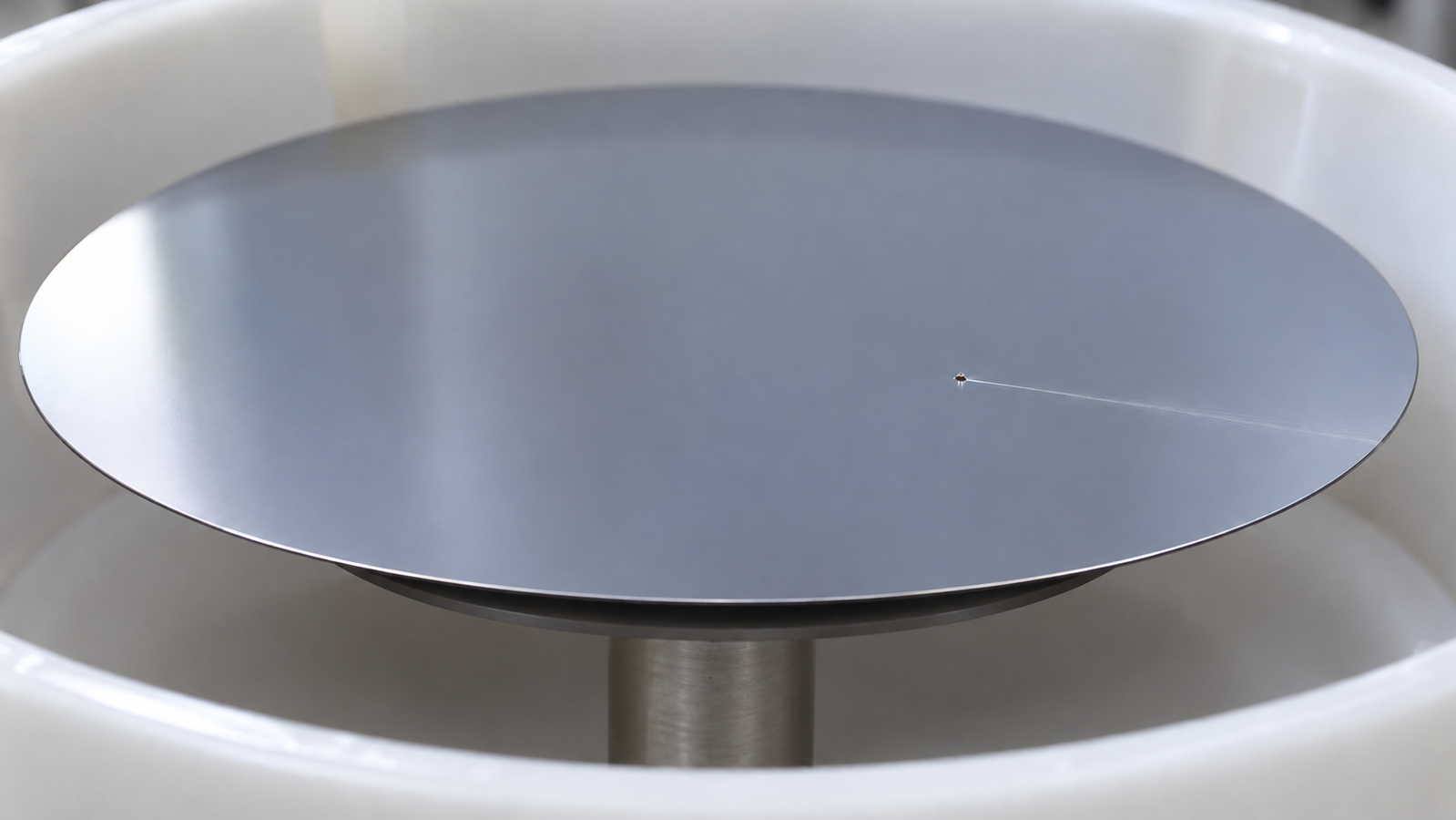
In one paragraph: look first at shape, position and repeatability. A streak with a point-like head is usually a comet from a particle or bubble; fine, regular radial lines across the film are usually striations from surface-tension gradients during drying; holes or a film pulling back into islands point to wetting; a thick rim is an edge bead; a zone matching the chuck is a chuck mark. Change one variable at a time, cheapest and most likely first: the ink, the substrate cleaning, the dispense, the spin program, the solvent system, and only then the hardware. No spin coater eliminates defects on its own.
1. How to read a defect
Before changing anything, describe the defect. Three questions separate most causes:
- What shape is it? A point with a tail, a round hole, a bare patch, fine parallel lines, a raised rim or a broad zone of different colour. Point-like defects usually start from something small; broad or regular patterns usually come from flow or drying.
- Where is it? Random positions suggest particles, bubbles or contamination. The centre suggests the dispense or the chuck. The edge and corners suggest edge bead, airflow or splash-back. A zone that matches the chuck diameter suggests a chuck mark.
- Does it repeat? The same place on every substrate points to the hardware, dispense or holder; a defect that moves points to the ink, the surface or the environment; one seen only on the first substrates of a session can point to the atmosphere in the bowl.
Inspect under raking light and, where needed, a microscope. Interference colour is a qualitative map of thickness, not a measurement. The physics of how a film forms, the four stages of spin coating and the classic thickness models are covered in Spin Coating Explained: Stages, Physics and Film Thickness; this guide assumes that background.
2. Symptom, cause, what to change
The table summarises sections 3 to 8. Treat the causes as a checklist, not a ranking; change one thing at a time and keep a record.
| Symptom | What it looks like | Likely causes | What to change first |
|---|---|---|---|
| Comet | A tail running outwards from a point-like head | Particle on the substrate or in the ink; bubble in the ink | Filter or replace the ink; let it outgas; clean the substrate just before coating |
| Pinholes | Small round holes at random positions | Particles, bubbles, local contamination; holes opening during bake | Improve cleaning; check the ink and the wetting |
| Uncoated areas, fingers | Bare sectors or radial fingers | Too little ink; off-centre dispense; spreading front breaking into rivulets | More volume; centred dispense; faster ramp on smooth substrates |
| Dewetting | Film pulls back into islands, droplets or cells | Ink does not wet the surface; low-energy or contaminated surface | Clean or treat the surface; review adhesion promoter; reformulate |
| Striations | Fine, regular radial lines | Surface-tension gradients from evaporation | Change solvent or co-solvent; slow evaporation |
| Edge bead | Thick rim on a round substrate | Edge flow and drying; worse with thick films and low speeds | Edge bead removal; higher-speed step at the end |
| Corner buildup | Thick corners and edges on squares | Local flow, airflow and drying differences | Measure the active area; leave a margin; evaluate a recessed carrier |
| Centre spot | Spot or ring at the centre | Late drop, drip, bubble or splash at dispense | Check tip, timing and height |
| Chuck mark | Zone matching the chuck size or vacuum pattern | Heat exchange with the chuck; chuck design | Equalise temperatures; compare chucks |
| Splash-back spots | Spots near the edge after film formation | Spun-off liquid rebounding from bowl or lid | Clean the bowl; check drainage and the lid |
| Swirls, cloudy zones | Broad, irregular thickness changes | Turbulence; very volatile solvent; changing atmosphere | Close lid openings; review exhaust; run dummy substrates |
General guidance from the references in section 13 and standard practice; typical, not exhaustive. Verify each change on your own process.
3. Comets, particles and bubbles
A comet is a point-like head with a tail of thinner or missing film running outwards: an obstacle the outflowing liquid has to pass around. Comet-shaped discontinuities or thinning often start with air bubbles in the ink or with particles in the ink or on the substrate.1 Because both are usually microscopic, bubbles are often mistaken for particles.1 Under a microscope, a hard, irregular head suggests a particle; a round crater suggests a bubble.
Particles on the substrate
Particles that are already on the substrate before coating can be removed with a cleaning step; if they come from the room air, blowing the substrate off with clean nitrogen immediately before coating can remove a fraction of them.1 Keep the time between cleaning and coating short.
Particles and gel in the ink
Particles can also come from the ink itself. For photoresists, an expired material, storage at too high a temperature or excessive dilution can promote particle formation, and highly diluted resists may start to gel and leave millimetre-sized clots of the same colour as the film.1 For other inks, aggregates, undissolved material or precipitation play the same role. Filtering just before use, with a filter the solvent does not attack, fresh solution and clean dispense tips are the usual first steps.
Bubbles
Air bubbles are often introduced while transporting, refilling or pipetting the ink.1 Letting the container stand undisturbed lets them rise and escape; the time needed grows with viscosity.1 Some photoresist chemistries can also release dissolved gas that forms bubbles when a stored bottle is opened.1 Pipette slowly and dispense from a low height so the ink does not trap air.
4. Pinholes, uncoated areas and dewetting
These defects share a root: the liquid never covered part of the surface, or left it again. Whether a liquid spreads or retracts depends on the balance of solid, liquid and interfacial energies, usually discussed through the contact angle and spreading coefficient.4
Pinholes
Pinholes can come from a particle or bubble that leaves no tail, or from a spot of contamination the ink does not wet. Locally poor wetting can come from earlier process steps, insufficient cleaning, incorrect use of an adhesion promoter, or residues left by dried droplets of contaminated chemicals or water.1 Holes that appear only after baking suggest dewetting (below).
Uncoated areas and fingering
Bare sectors or radial fingers mean the liquid did not cover the surface before it thinned. Possible reasons are too small a dispense volume, whose optimum depends on the substrate size, target thickness, viscosity and spin program, and an off-centre dispense.1 For smooth substrates, a fast ramp to the final speed can suppress uncoated areas; the source illustrates this with ramps above 1,000 rpm/s in its example.1 Textured substrates may need a two-step program instead: a short low-speed spread, then the final speed.1
The fingers themselves are a flow instability. In the experiments reported by Fraysse and Homsy, the spreading front became unstable beyond a critical radius that depended on wetting conditions.3 Better wetting and enough volume tend to reduce fingering. Recipes are covered in Spin Coating Acceleration and Multi-Step Recipes and Static vs Dynamic Dispense in Spin Coating.
Dewetting
Dewetting is the film pulling back from a surface it covered, either while still liquid or later, when a dried but mobile film is heated. In a classic study, thin polystyrene films on silicon heated above their glass transition dewetted by forming holes that grew and developed rims; touching rims produced a cellular pattern, and the rims finally broke up into droplets.5 A film that looks fine after spinning but shows holes or a cellular pattern after the bake fits this picture. Remedies act on the surface (cleaning, treatment, an adhesion layer), the ink or the bake. Surface energy will be covered in Ink Dewetting and Surface Energy (coming soon).
5. Striations and drying defects
Striations are fine, fairly regular radial thickness ridges across much of the film: a drying defect, not contamination. During spinning, solvent evaporation depletes the surface of the more volatile components while the liquid is still flowing outwards. Depending on how the surface composition changes, this can stabilise or destabilise the surface against convection; when the surface tension rises at the surface, surface-tension-driven (Marangoni) flows can develop and the pattern is frozen in as the film sets.2
The main remedy is usually in the ink. Birnie's analysis cross-references solvent volatility with surface tension and suggests, as one result, that a fully miscible solvent with a higher surface tension than the deposited solid is favourable; mixed-solvent and water-containing systems are also discussed.2 Changing the solvent or adding a co-solvent can suppress striations, but the choice must be tested for each ink. Slowing evaporation with a closed lid or a solvent-rich atmosphere may also help; that is a general expectation, not a guaranteed fix.
A single streak with a head is a comet (section 3); broad, irregular zones usually point to airflow (section 8).
Skin formation
Evaporation can also make the surface of the film more concentrated than the bulk. A one-dimensional model of spin coating by Bornside and co-workers predicts that such a skin can form during spinning, that it can lead to defects if flow is still active when it forms, and that partial saturation of the gas above the film delays its formation.7 If film quality changes with the lid, exhaust or ambient conditions, drying is a likely factor.
Very low-boiling solvents can also dry too quickly to form a homogeneous film.1
6. Edge beads and corner buildup
Edge bead on round substrates
An edge bead is a raised rim of film around the edge. It forms especially with thick films and with square substrates.1 In contact lithography the rim can stick to the mask and act as a spacer, reducing resolution.1 Lower spin speeds can give a more pronounced edge bead.1
Options listed for reducing it include: edge bead removal with a suitable solvent while the substrate spins at low speed (not a high-vapour-pressure solvent such as acetone); an ink that reaches the target thickness at a higher speed; a short higher-speed step for very thick films; an abrupt speed increase at the end of coating, when the film has dried enough but the bead is still liquid; several thinner coats; and a waiting period or stepped drying before the bake, so that the bead does not flow when its viscosity drops at bake temperature.1 Automated edge bead removal and backside rinse will be covered in Edge Bead Removal and Backside Rinse (coming soon).
Corner and edge buildup on square substrates
The classic models assume an axisymmetric disc and cannot predict the thickness distribution on a square. Buildup can occur because local flow, airflow and drying differ near edges and corners. One source attributes it to air turbulence at the edges and above all the corners, which accelerates drying there and suppresses the spin-off of liquid.1 In a simulation and experimental study, a flow model without evaporation showed little effect of substrate shape while experiments differed markedly; the authors identified solvent evaporation, which the model neglected, as the dominant factor.8 The extent depends on the substrate, the chuck, the ink and the recipe.
Practical responses: measure the area you will use, leave an edge margin, and, if needed, evaluate a recessed carrier that holds the substrate as a close inlay, or an edge treatment.1 Breaking off the edge pieces or wiping the bead are further options.1 Chucks and vacuum for square pieces are covered in Spin Coating Small, Square and Fragment Substrates.
7. Centre spots and chuck marks
Centre spots
A defect at the exact centre usually points to the dispense: a late drop from the tip, a bubble in the last of the liquid, a splash from too great a height, or dried ink at the tip. Check the tip, dispense from a consistent low height and, for a dynamic dispense, make sure the liquid lands before the program moves on. If the spot persists, compare another chuck.
Chuck marks
A zone of different thickness that matches the size or shape of the chuck, or the pattern of its vacuum grooves, is a chuck mark. Thickness variations associated with the vacuum chuck have been reported in spin-coated films, controlled by factors such as the thermal properties of the substrate, the evaporation behaviour of the solution and the physical design of the chuck.6 A plausible picture is that heat exchange with the chuck changes local evaporation, which itself cools the film.
To try, one at a time: let substrate and chuck reach the same temperature before dispensing; compare chucks of different contact area; check the chuck face for residue or damage.
8. Bowl, lid, exhaust and atmosphere
Openings in a coater cover can cause turbulence over the film during rotation and non-uniform drying; one source recommends covering such openings from the inside so the cover forms a smooth surface.1 The inner walls of the bowl should deflect spun-off liquid downwards, not back onto the substrate as droplets.1 Spots near the edge after the film has formed suggest splash-back; clean the bowl and check that waste drains.
The solvent vapour above the film matters too. For photoresists under the conditions discussed in the cited note, a more saturated atmosphere lowers evaporation and can give a thinner film; after cleaning the coater or after a long idle period, coating a few dummy substrates first can help reach a constant thickness.1 A cover that rotates with the substrate reduces air movement over the film and can change the attained thickness substantially.1 These are process-specific observations, but they show why exhaust and lid settings belong in the recipe record.
Humidity and temperature can matter too, especially for moisture-sensitive inks; record them with each run.
9. A troubleshooting routine
Before changing the ink or spin program, confirm that the substrate and approved holder are clean, correctly seated and centred, and that the required vacuum, exhaust, guards and interlocks are functioning. Stop if there is substrate movement, abnormal vibration or a vacuum alarm; do not compensate for a holding fault by tuning the coating recipe. Once these basic conditions are verified, change one process variable at a time and compare repeated coatings.
- Document and classify the defect with section 1 and the table in section 2.
- Check the cheap causes first: fresh, filtered, outgassed ink; a freshly cleaned substrate; a clean dispense tip; a clean bowl and chuck.
- Change one variable at a time, with at least two substrates per condition.
- Measure, do not only look. Interference colour shows where thickness changes, not by how much. If the measurement uncertainty is comparable to the differences you are trying to see, quantify it before drawing conclusions. A dedicated guide is planned: How to Measure Thin Film Thickness (coming soon).
- Record the full recipe: ink batch, dispense, every spin step, lid and exhaust, ambient conditions and bake.
- Only then consider different hardware, such as another chuck or an edge treatment. Basic holding and equipment checks are not part of this step; they come first, as above.
Speed also changes drying time, edge bead and airflow, so after changing it re-check thickness against your spin curve; see Spin Speed vs Film Thickness: How to Build and Use a Spin Curve.
10. Spin coater features and defect control
A spin coater cannot correct a contaminated ink or a non-wetting surface, and no model eliminates defects on its own. Some features relate to the defect classes above: substrate hold, bowl and splash handling, edge and backside treatment, and dispensing. The table is a selected comparison, not a complete catalogue; features belong to the configuration named.
| Model | Substrate range or chucks (as published) | Vacuum monitoring/control, as published | Edge, backside and splash options |
|---|---|---|---|
| EZ6-S | Chucks 10 mm, 25 mm, 2-inch | Vacuum and lid safety interlock system | Anti-resin-infiltration and anti-resin-clogging features |
| AC200-S-PP | 1 cm debris to max. 8-inch standard wafers; standard trays 10 mm, 25 mm, 2-inch | Digital display of vacuum adsorption pressure; adjustable vacuum pressure | Integrated backside cleaning and edge debonding; integrated 4-channel auto-dispensing ports, upgradeable to multi-channel dispensing (optional) |
| AC200-SE | Fragments to 8-inch circular wafers; tray diameters 10 mm, 25 mm, 2-inch | Not stated on the page | BSR and EBR can be added; integrated rinse/develop module with splash guard (optional); four-way automatic dispensing port, upgradeable to multi-way automatic dispensing |
| AC200-PE | Fragments <1 cm to 8-inch circular substrates; standard trays 10 mm, 25 mm, 2-inch, 4-inch or 6-inch | Not stated on the page | BSR and EBR can be added; spill-proof cleaning and developing can be added; four-way automatic dispensing port, upgradeable to multi-way automatic dispensing |
| AC200-SE-PLUS | Fragments <1 cm to max. 8-inch standard wafers; trays not listed | Not stated on the page | BSR and EBR can be added; spill-proof cleaning and developing can be added |
| AC300-S-CTM | Fragments <1 cm to standard wafers up to 12 inches | Precision vacuum pressure regulation with a real-time digital vacuum display | BSR and EBR can be added; splash-proof cover washing and developing can be added; PTFE-coated stainless steel chamber |
Features from the Levon™ product pages as listed on 22 October 2026, in the pages' own wording. “Not stated” means the page lists no vacuum display or regulation for that configuration; it does not mean that the configuration lacks vacuum holding. BSR = backside rinse; EBR = edge bead removal. The full range is on the Levon™ spin coaters page.
How the features map to the defects
A listed feature is not a demonstrated outcome. The table separates features a page lists as integrated from those it says can be added and from custom configurations; check which applies to the configuration you are considering.
- Edge and backside treatment: edge bead removal and backside rinse treat selected regions through configuration-specific processes. Their timing and interaction with the coating depend on the equipment and recipe. They are not substitutes for correcting poor coverage, contamination or unstable drying across the active area.
- Splash-back and bowl cleaning: bowl material, geometry and splash guards affect where spun-off liquid goes; the EZ4-S has a single-mold cavity with a quick-disassembly design for easy cleaning and replacement.
- Vacuum monitoring: a vacuum display helps the operator monitor the reported vacuum condition and identify changes between runs. It does not by itself establish an adequate seal, substrate retention at the selected speed, or repeatable film thickness. Follow the holder and instrument requirements for the actual substrate.
- Dispensing: automated dispensing can support repeatable delivery, but its performance depends on the installed metering hardware, nozzle arrangement, liquid properties and synchronization with the spin program. A listed dispensing port alone does not establish delivered-volume accuracy or repeatability.
- Atmosphere: a recipe that is defect-free in air may behave differently in a glovebox. The EZ4-S page describes a glovebox-compatible design, and all four AC200 configurations can be recessed into a glovebox; the other pages listed here do not mention glovebox use.
Before you request a quote
- The defects you see: photographs and where they appear.
- Speed window and recipe control: the speeds, ramps and number of steps your process needs.
- Substrates: material, shape, dimensions, thickness, and the chuck or carrier required.
- Edge and backside: whether you need edge bead removal, backside rinse or an edge-free margin.
- Environment: air or glovebox, exhaust, and whether heating is needed.
- Measurement: target dry thickness, method, locations and acceptable variation.
Send these through the contact form or the Get Quote request on the product page.
11. Keep Exploring the Spin Coating Knowledge Hub
This article is part of the spin coating section of the ACS Material thin-film library. Articles on heated spin coating, choosing a spin coater and measuring film thickness will be added here as they are published.
Start here
- Spin Coating Explained: Stages, Physics and Film Thickness — the four stages of spin coating and the models behind film thickness.
- Solution-Processed Thin Films: Choosing Spin, Dip, Slot-Die or Blade Coating — when spin coating is the right method at all.
Coming soon in this series
- Spin Speed vs Film Thickness: How to Build and Use a Spin Curve
- Spin Coating Acceleration and Multi-Step Recipes
- Static vs Dynamic Dispense in Spin Coating
- Spin Coating Small, Square and Fragment Substrates
- Ink Dewetting and Surface Energy (coming soon)
- Edge Bead Removal and Backside Rinse (coming soon)
Spin coating equipment
- Levon™ spin coaters — compact, programmable, servo and heated spin coaters.
- EZ6-S benchtop spin coater — touchscreen recipe control, anti-resin-infiltration features and a vacuum and lid safety interlock.
- AC200 programmable servo spin coater and AC300-S-CTM servo spin coater — servo-driven coaters with edge and backside options for larger wafers.
12. FAQ
What causes comets in spin coating?
Usually a particle or bubble in the ink or on the substrate; the outflowing liquid passes around it and leaves a tail. Filter and outgas the ink and clean the substrate just before coating.
What causes striations in spin-coated films?
Usually drying: evaporation changes the surface composition, and when this raises surface tension, Marangoni flows can develop and freeze into radial ridges. A different solvent or co-solvent can suppress them.
Why does my film have pinholes?
Common causes are particles, bubbles and spots of contamination the ink does not wet. If holes appear only after the bake, the film may be dewetting while hot.
How do I reduce the edge bead?
Options include solvent edge bead removal, a short higher-speed step or abrupt speed increase at the end, an ink that reaches the target at a higher speed, thinner multiple coats and a wait before the bake.
Why are the corners of my square substrate thicker?
Classic models assume a round disc. Buildup can occur because local flow, airflow and drying differ near edges and corners. Measure the area you will use and leave a margin.
Can a better spin coater eliminate defects?
No. Most defects come from the ink, the surface, the environment or the recipe. Edge and backside treatment, splash control, well-controlled dispensing and a correctly verified hold can help with specific defect classes, but a listed feature does not by itself establish a better film; see section 10.