
Many laboratory samples are not round wafers: they are 10–25 mm squares of glass, ITO or silicon, cleaved fragments, or rectangular slides. Spin coating a square substrate or a fragment raises three practical questions that a round wafer rarely does: which chuck can hold the piece, how securely it is held at speed, and how much of the film near the edges and corners is usable. This guide covers chuck and vacuum basics, why centring and speed matter, what is known about corner buildup, checks that reduce the risk of a substrate leaving the chuck, and the substrate ranges and chucks published for Levon™ spin coaters.
In one paragraph: use a holder whose required sealing region the substrate fully covers while receiving adequate support, within the substrate sizes, thicknesses and materials the holder supports, and never use a fragment that does not cover the vacuum opening. The appropriate chuck size is design-specific. Centre the piece carefully: an off-centre substrate experiences a net outward force that grows with the square of the spin speed. Expect a thicker rim and thicker corners on square pieces, because the round-disc models of spin coating do not describe corners; measure the area you will use and leave a margin. Use the approved limits and operating procedure for the instrument, holder and substrate combination; do not find a limit by raising the speed until the piece moves. For pieces too small or too irregular for a vacuum chuck, a carrier, a recessed holder or a mechanical holder is the usual alternative.
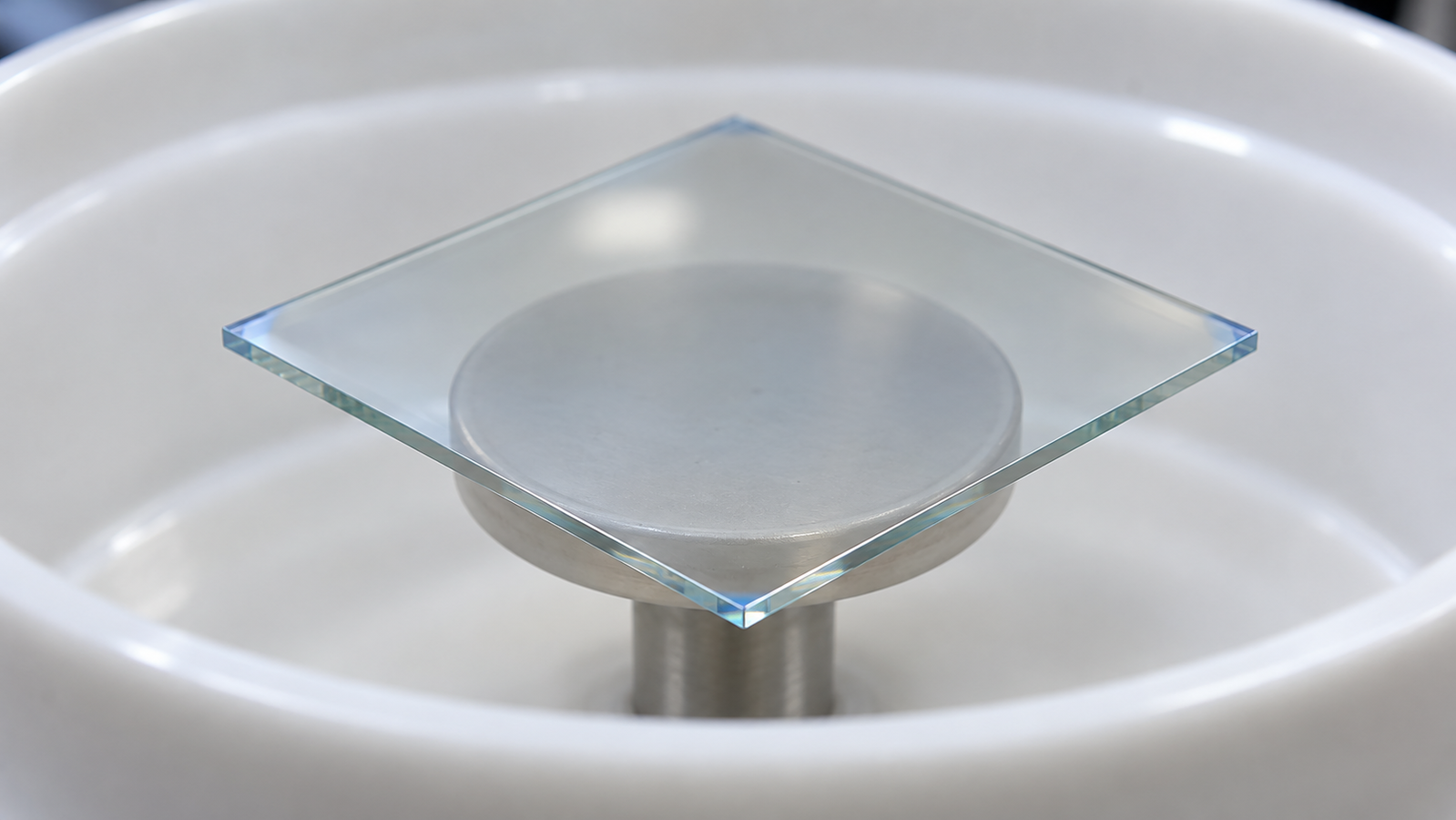
1. Why small and square pieces are different
The classic description of spin coating treats a liquid on an infinite, flat, rotating disc. Emslie, Bonner and Peck showed that for a Newtonian liquid on such a disc, centrifugal outflow tends to level an initially uneven film,2 and Meyerhofer added evaporation to explain how the final thickness depends on spin speed.3 These models are axisymmetric: every point at the same radius behaves the same way. They are the basis of the spin curve described in Spin Coating Explained, and they work well over the central area of a round wafer.
A square substrate breaks that symmetry. Its corners lie farther from the axis than its edge midpoints, the liquid leaving each edge meets the edge at different angles, and the air near the corners is disturbed as they sweep round. The models therefore cannot predict the thickness distribution near corners and edges. A small substrate adds a second issue: the edge, where the film behaves differently, is a large fraction of the total area. On a 10 mm square, a rim a millimetre or two wide (an illustrative width) takes up a large share of the surface.
The third difference is mechanical. A round wafer sits on a round chuck that it covers symmetrically. A square or irregular piece may cover the chuck only partly, may be placed off-centre, and has less area for the vacuum to act on. The rest of this guide takes these three issues in turn: holding, corners and edges, and the special case of fragments.
2. Choosing a chuck
A vacuum chuck holds the substrate by the pressure difference between the atmosphere above it and the reduced pressure in the channels or grooves under it. The hold depends on the area over which that difference acts and on the seal around it: if the substrate does not cover the vacuum opening completely, air leaks in and the hold drops. For square and small substrates, a few general rules follow.
- The substrate must cover the sealing region. For a conventional vacuum chuck, the substrate must cover the required sealing region while receiving adequate support. The appropriate chuck size is design-specific; recessed, porous and mechanical holders follow different requirements. If part of the vacuum area is left uncovered, air leaks in and the exposed chuck face can be wetted by the coating liquid.
- Support matters too. A large overhang leaves the outer part of a thin or flexible substrate unsupported, and the overhang can bend or vibrate at speed. How much overhang is acceptable depends on the material, thickness and speed; there is no general rule.
- The substrate should be flat on the backside where it meets the chuck. Warped, rough or textured backsides, residues and particles can open leak paths and reduce the hold.
- The chuck face should be clean and undamaged. Dried coating, a scratch across the sealing surface or a particle can open a leak path; check the chuck before every session.
Several Levon™ models list standard chucks of 10 mm, 25 mm and 2-inch. Geometrically, a centred 10 mm circle fits within a 15 mm square, while a centred 25 mm circle is tangent to the sides of a 25 mm square. Neither observation establishes adequate vacuum sealing, acceptable overhang or an approved operating speed. Select the holder using its actual seal geometry and the manufacturer's supported substrate sizes, thicknesses and materials. Do not assume that the smaller chuck is the safer or more forgiving option.
The chuck also affects the film. Birnie and colleagues found that thickness variations associated with the vacuum chuck are controlled by the thermal properties of the substrate, the evaporation of the solution and the design of the chuck.7 A chuck of a different material or size can therefore change the film above it, especially on thin substrates; this is covered further in section 7.
3. Why centring and speed matter
If a substrate of mass m is perfectly centred, the outward forces on its parts balance and there is no net radial force on it. For a rigid substrate whose centre of mass is offset from the rotation axis by a distance e, the magnitude of the radial force required to maintain circular motion is
with angular speed ω in rad/s (ω = 2π × rpm / 60). This explains two trends: doubling speed quadruples this force, and better centring reduces it.
This equation does not determine a safe operating speed. Even a centred substrate must withstand acceleration and braking torque. Retention also depends on the actual seal, effective vacuum area, leakage, contact condition, substrate stiffness and holder design. Use the approved limits and operating procedure for the specific instrument, holder and substrate combination; do not derive an operating limit from assumed friction and vacuum values.
Acceleration and braking add a tangential load: the holder has to bring the substrate up to speed and slow it down again. A substrate that slips on the chuck can leave a blurred or off-centre film pattern. Liquid that reaches the interface between substrate and chuck can also reduce friction. Ramps and multi-step programs are covered in Spin Coating Acceleration and Multi-Step Recipes.
4. Checks against slip and fly-off
A substrate that leaves the chuck at speed can break, damage the bowl or lid, and scatter wet coating. The following checks reduce the risk; they do not replace the instrument manual or your laboratory's safety rules.
- Centre the piece. Use a centring template, a marked chuck or a simple jig so that placement is repeatable. Even a small offset matters at high speed.
- Check that the piece covers the vacuum opening. If the instrument has a vacuum display, note the reading with the substrate in place; a reading noticeably different from usual points to a leak, a warped substrate or a dirty chuck. Do not start the program if the hold is not established.
- Dry checks only as specified. Perform any empty-holder or dry-substrate check only as specified by the manufacturer's procedure, with the required enclosure and interlocks active. A successful dry run does not establish that a wet substrate, a different ramp or a higher speed is safe. Do not determine an unknown operating limit by progressively increasing speed until the substrate moves.
- Keep the lid closed and interlocks active. Never bypass a lid or vacuum interlock to see the substrate. The EZ6-S page, for example, lists a vacuum and lid safety interlock system.
- Stay within the approved limits for the instrument, holder and substrate combination, including speed, ramps and braking.
- Look at the film. A spiral, smeared or off-centre pattern can indicate that the substrate slipped or was off-centre; check the hold before the next run.
If a piece is too small or irregular to pass these checks on a vacuum chuck, use one of the holding methods in section 6 instead.
5. Corners, edges and usable area
Spin-coated films are often thicker near the edge than in the centre, and on square substrates the buildup is often strongest at the corners. A widely used application note describes the mechanism for photoresists on square or rectangular substrates: air turbulence at the edges and above all at the corners accelerates drying there, which suppresses spin-off of the resist and leaves a raised rim.1 Studies on rectangular substrates point the same way. Yan and colleagues examined the effect of evaporation on the thickness distribution on rectangular and circular substrates.4 Liu and co-workers found that airflow disturbance affected thickness uniformity on the large rectangular substrates they studied. Their evaporation-suppression comparison supported changes in solvent evaporation, rather than direct air-shear forcing, as the dominant explanation under those conditions. The study does not show that airflow is unimportant or establish one mechanism for every small square substrate.5
The practical message is the same whichever mechanism dominates in a given case: corner and edge buildup comes from local flow, airflow and drying near the edges, and its width and height depend on the substrate, chuck, ink and recipe. No general rule gives the width of the affected zone. Ways to deal with it:
- Measure the active area. Measure thickness at the centre and along lines towards an edge and a corner, on the same substrate size you will use, and define the usable area from the measurements. Methods are covered in How to Measure Thin Film Thickness (coming soon).
- Leave a margin. Lay out devices or measurement spots inside the uniform area; on small pieces, consider a larger substrate if the usable area is too small.
- Use a recessed holder. The application note lists a well-adjusted cavity in the substrate holder, with the substrate as a close inlay, as one way to reduce the edge bead.1 The surrounding holder then acts like an extension of the substrate surface, so the thick film edge can move outwards onto the holder. The fit and flushness matter, and liquid in the gap has to be managed. Liu and Zhou subsequently studied how the slits between a rectangular substrate and a recessed chuck affect edge buildup. The recess geometry is therefore a design variable in its own right: a closer-fitting recess should not be assumed to be better, and its geometry must be selected and validated for the process.6
- Treat the edge. For non-circular substrates the same note suggests breaking off the edge pieces together with the edge bead where possible, or wiping the edge bead with cleanroom wipers;1 solvent edge bead removal is another option on instruments that offer it. See Edge Bead Removal and Backside Rinse (coming soon).
- Adjust the recipe. Options described for the edge bead in general, such as a short higher-speed step at the end or an ink that reaches the target thickness at a higher speed, can also reduce corner buildup; their effect on a particular substrate has to be measured.
Corner buildup is one of several defects with a recognisable signature; the others are diagnosed in Spin Coating Defects: Comets, Striations, Pinholes and Edge Beads Diagnosed.
6. Fragments and very small pieces
A fragment smaller than the smallest available chuck cannot seal the vacuum opening and should not be spun directly on that chuck. Irregular fragments also make centring difficult. Common alternatives:
- A carrier arrangement. The fragment sits on or in a larger carrier, such as a wafer or slide, which is then held on the chuck. Use a holder or carrier arrangement approved for the fragment's material, dimensions, thickness, chemical exposure and intended speed; a carrier's fit on the spindle does not by itself establish safe retention of the fragment. The carrier also changes how the liquid leaves the fragment edges.
- A recessed or limited-position holder. A holder with a pocket matched to the fragment locates it mechanically and, if flush and correctly dimensioned, can reduce edge buildup; as section 5 explains, a closer fit is not automatically better.
- A mechanical holder. A clamp or jaw holder grips the edges instead of using vacuum. It works on pieces that cannot seal a vacuum opening, but the jaws sit at the edge and affect the flow there, so the film next to them is usually not usable.
Small pieces also need less liquid; most of a typical dispense volume is spun off, and excess can increase splashing and edge effects. Dispense methods are compared in Static vs Dynamic Dispense in Spin Coating.
7. Backside wicking and chuck marks
When a substrate overhangs the chuck, liquid can creep round the edge and along the underside. On thin pieces it can reach the chuck, where it contaminates the chuck face, weakens the hold and may glue the substrate to the chuck. Ways to reduce it include keeping the dispense volume no larger than needed, cleaning the chuck regularly, and using a backside rinse where the instrument provides one.
Chuck marks are the opposite effect: a thickness change in the film above the chuck, with the chuck's outline. Because heat exchange between substrate and chuck can change local evaporation, thin substrates and chucks of different materials can show different marks.7 If a mark appears, compare substrates of different thickness, try a different chuck size or material where available, and check for residue on the chuck face.
8. Levon™ substrate ranges and chucks
The table lists the substrate ranges, chucks and trays as published on each Levon™ product page. It is a selected comparison, not a complete catalogue; features belong to the configuration named, and “not stated” means the page does not give the value.
| Model | Substrate range (as published) | Chucks or trays (as published) | Holding-related features |
|---|---|---|---|
| EZ4-S | Maximum recommended: 4-inch round substrates | 10 mm, 25 mm, 2-inch | Glovebox-compatible design |
| EZ6-S | Not stated | 10 mm, 25 mm, 2-inch | Vacuum and lid safety interlock system |
| AC100-S | Not stated | 10 mm, 25 mm, 2-inch | — |
| AC200-S-PP | 1 cm debris to max. 8-inch standard wafers | Standard trays 10 mm, 25 mm, 2-inch | Digital display of vacuum adsorption pressure; adjustable vacuum pressure |
| AC200-SE | Fragments to 8-inch circular wafers | Tray diameters 10 mm, 25 mm, 2-inch | — |
| AC200-PE | Fragments <1 cm to 8-inch circular substrates | Standard trays 10 mm, 25 mm, 2-, 4- or 6-inch | — |
| AC200-SE-PLUS | Fragments <1 cm to max. 8-inch standard wafers | Not listed | — |
| AC300-S-CTM / AC300-S-EN | Fragments <1 cm to standard wafers up to 12 inches | Not listed | Precision vacuum pressure regulation with a real-time digital vacuum display |
| IC5000-S | 10–35 mm square or circular substrates (other specifications customizable) | Adjustable jaw chuck stage | Mechanical (jaw) holding |
| IC8000-S | Glass fragments/substrates and 6-inch glass or semiconductor wafers | Not listed | — |
From the Levon™ product pages as listed on 22 October 2026, in the pages' own wording. “—” means no holding-related feature is listed for that configuration. Substrate thickness limits are not stated on any of the pages. The AC300-S-CTM page offers custom solutions for larger and heavy-duty substrates, and the custom AC200-based process systems (custom configurations, on quotation; not included with a standard AC200 configuration) list a PPS vacuum suction or limited-position chuck/tray selected according to substrate size; suitability for a given fragment has to be confirmed. The full range is on the Levon™ spin coaters page.
Reading the table for small and square pieces: the 10 mm chuck or tray is the smallest standard size listed, so pieces that do not fully cover it need one of the methods in section 6. Where a page lists fragments smaller than 1 cm, it does not identify the holder and operating limits for every fragment geometry. Confirm the required holder using the fragment's dimensions, thickness, material and intended spin program. The IC5000-S jaw chuck is the only holder in the table that grips square substrates mechanically, within its published 10–35 mm range. For glovebox work, the EZ4-S page describes a glovebox-compatible design and all four AC200 configurations can be recessed into a glovebox; the other pages do not mention glovebox use.
Before you request a quote
- Substrates: material, shape, side lengths or diameter, thickness, and whether the backside is flat and polished.
- Smallest and largest pieces: including fragments, and how many sizes you need to coat.
- Holding: vacuum chuck, tray, recessed holder, carrier or mechanical holder, and any chuck material constraints.
- Usable area: how close to the edges and corners the film has to be usable.
- Process: speed window, ramps, solvent, edge or backside treatment, heating, and air or glovebox.
Send these through the contact form or the Get Quote request on the product page.
9. Keep Exploring the Spin Coating Knowledge Hub
This article is part of the spin coating section of the ACS Material thin-film library. Articles on heated spin coating, choosing a spin coater and measuring film thickness will be added here as they are published.
Start here
- Spin Coating Explained: Stages, Physics and Film Thickness — the four stages of spin coating and the models behind film thickness.
- Solution-Processed Thin Films: Choosing Spin, Dip, Slot-Die or Blade Coating — when spin coating is the right method at all.
Coming soon in this series
- Spin Speed vs Film Thickness: How to Build and Use a Spin Curve
- Spin Coating Acceleration and Multi-Step Recipes
- Static vs Dynamic Dispense in Spin Coating
- Spin Coating Defects: Comets, Striations, Pinholes and Edge Beads Diagnosed
- How to Choose a Spin Coater
- Edge Bead Removal and Backside Rinse (coming soon)
Spin coating equipment
- Levon™ spin coaters — compact, programmable, servo and heated spin coaters.
- EZ4-S compact spin coater — 10 mm, 25 mm and 2-inch chucks, for round substrates up to the recommended 4 inches.
- IC5000-S heated spin coater — adjustable jaw chuck stage for 10–35 mm square or circular substrates.
- AC200 programmable servo spin coater — configurations from fragments to 8-inch wafers.
10. FAQ
Can I spin coat a square substrate on a round chuck?
Yes, this is common. The substrate must cover the chuck's required sealing region and be adequately supported, within the sizes the holder supports; centre it carefully and expect thicker corners.
What size chuck should I use for a 15 mm square?
Geometrically, a centred 10 mm chuck fits within a 15 mm square and a 25 mm chuck does not, but geometry alone does not establish an adequate seal or an approved speed. Select the holder using its actual seal geometry and the supported substrate sizes, thicknesses and materials, and follow the instrument's procedure for any check.
Why are the corners of my film thicker?
Round-disc models do not describe corners. Local flow, airflow and drying near the corners suppress spin-off there; the extent depends on substrate, chuck, ink and recipe. Measure the active area and leave a margin.
Why did my substrate fly off the chuck?
Common causes are an off-centre piece, a fragment that does not seal the vacuum opening, a warped or dirty backside, residue on the chuck, liquid under the substrate or too steep a ramp for a heavy piece.
How do I coat a fragment smaller than the chuck?
Use a carrier arrangement, recessed or limited-position holder, or mechanical holder approved for the fragment's material, dimensions, thickness, chemical exposure and intended speed. Do not spin it directly on a chuck it does not cover.
Does a recessed holder remove corner buildup?
It can reduce it by moving the film edge onto the holder, but the recess geometry matters, and a closer fit should not be assumed to be better. Select and validate the geometry for the process, and measure the remaining non-uniformity.