
Before a spin coater can thin anything, the liquid has to reach the substrate, and there are two basic ways to put it there. In a static dispense the liquid is placed on a substrate at rest, which then starts to spin; in a dynamic dispense it is placed on a substrate that is already turning. The choice affects spreading, the volume needed for coverage, sensitivity to timing and centring, and how much solution ends up in the bowl. This guide compares static vs dynamic dispense, explains how dispense volume affects coverage and why its effect on thickness should still be measured, shows how to find the smallest volume that covers reliably, and lists the dispensing options published on the Levon™ spin coater pages.
In one paragraph: static dispense is simple and works with a hand pipette, but the whole puddle must spread during spin-up, so it relies on enough volume, good centring and a suitable ramp. Dynamic dispense spreads the liquid as it arrives, which can help coverage and material use for some inks, but adds timing and delivery variables. Once a substrate is fully covered and the process is operating in a suitable regime, adding more solution often increases waste rather than final film thickness; confirm this by measuring dry thickness when the volume changes. Find the minimum volume that covers reliably for each method, add a tested margin, and keep the dispense fixed once a recipe works.
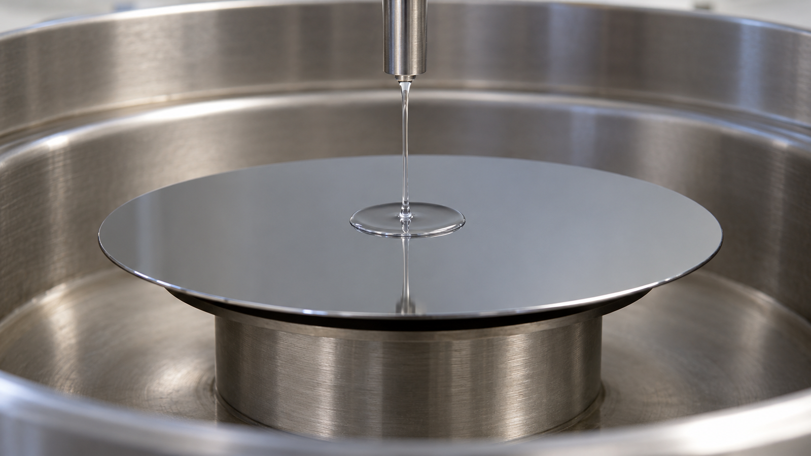
1. The short answer: static vs dynamic dispense
The static vs dynamic dispense question is about when the liquid meets the rotation. A photoresist application note describes both in one sentence: typically a few ml of resist are dispensed on a substrate that is brought to a rotational speed of several 1000 rpm either before the dispense (dynamic spin-coating) or shortly after it (static spin-coating).1 The practical summary is:
- Static dispense places the whole volume first and then spreads it in one movement. It is easy to do by hand, but coverage depends on the puddle reaching the edge evenly.
- Dynamic dispense delivers liquid while the substrate rotates. Spreading occurs during delivery, but liquid can still accumulate near the landing point and the advancing front can still develop fingers. The additional controls include dispense speed, delivery rate and duration, nozzle position, and timing relative to any subsequent speed changes.
- Volume affects coverage first. Too little liquid, or liquid dispensed off centre, leaves uncoated areas; the optimum depends on the substrate size, film thickness, viscosity and spin profile.1 Above that threshold, extra liquid often goes into the bowl, but recheck thickness when the volume changes.
- Neither method is better in general; test both with everything else fixed.
The four stages of spin coating, and the conditions under which thickness becomes less sensitive to the initial liquid amount, are explained in Spin Coating Explained: Stages, Physics and Film Thickness. If you are still choosing a coating method, start with the guide to choosing spin, dip, slot-die or blade coating.
2. How the two methods differ
The table compares the two methods by mechanism. The entries describe tendencies that follow from how each method delivers the liquid; they are not measured comparisons, and a specific ink can behave differently.
| Aspect | Static dispense | Dynamic dispense |
|---|---|---|
| When the liquid lands | Substrate at rest; spin starts shortly afterwards | Substrate already rotating |
| How it spreads | The whole puddle spreads outward during spin-up | Liquid spreads outward from the landing point as it arrives |
| Main coverage risks | Puddle too small or off centre; fingering of the front during spin-up | Dispense too short or too slow for the substrate speed; liquid landing off centre |
| Timing sensitivity | Delay between dispense and spin (the puddle can start to dry or creep) | Dispense start, duration and rate relative to the rotation and any later speed change |
| Delivery | A hand pipette or a dispenser over a stationary substrate | Needs an approved means of delivering liquid while the substrate rotates, without reaching into the bowl |
| Typical use | Small substrates, viscous inks, textured surfaces with a spread step, manual work | Automated or repeated coating, inks that spread well while rotating |
Qualitative comparison based on the delivery mechanism. “Typical use” describes where each method is easiest to apply, not a rule.
Static dispense: everything happens at spin-up
After a static dispense, the substrate starts with a puddle near the centre. As it accelerates, the puddle spreads outward and its edge, the contact line, advances over the dry surface. Experiments on spinning drops show that this spreading is axisymmetric at first and that beyond a critical radius the front develops fingers.3 In one study, changing the wetting properties of the liquid significantly changed the critical radius and the number of fingers.3 If fingers reach the edge before the liquid between them fills in, the gaps can stay dry, so static dispense depends on enough liquid, good centring and a suitable ramp. For smooth substrates, the photoresist note reports that a high acceleration (> 1000 rpm/s) towards the final speed suppresses uncoated areas.1 A separate article, Spin Coating Acceleration and Multi-Step Recipes: What the Ramp Actually Does, will cover acceleration and multi-step recipes.
Static dispense also gives the liquid a moment to wet the surface before it is spun. For textured substrates, the note suggests distributing a comparatively large volume at a low speed (for example 1000 rpm) for a few seconds before ramping to the final speed, and warns that low-speed spinning should not last more than a few seconds, to avoid premature drying.1
Dynamic dispense: spreading as the liquid arrives
In dynamic dispense, liquid arrives while the substrate rotates; its distribution depends on the balance between delivery, outward flow and evaporation. Dynamic dispensing does not by itself eliminate a central puddle or an unstable advancing front. In experiments comparing liquid injected onto a rotating substrate with a released drop, injection tended to decrease the critical radius and the number of fingers at a high rotational Bond number, a dimensionless ratio of centrifugal to capillary forces, while the effect was negligible at a low Bond number.2 A related study of liquid injected onto a rotating wafer reported that in the early stage the spreading was mainly governed by the injection, that the critical injection rate for fully coating a wafer increased as the injection volume decreased, and that at a fixed rotating speed a higher injection rate could significantly reduce photoresist usage.7 The general point is that the way the liquid is delivered can change the spreading, not only the amount; the direction and size of the effect depend on conditions.
Dynamic dispense adds variables: substrate speed during dispense, delivery rate and duration, nozzle position and timing relative to any subsequent speed change. If they drift, for example because the delivery rate differs from run to run, coverage can drift too, so dynamic dispense is easiest to reproduce when delivery is mechanised and its timing is controlled.
Safety: Never reach into the bowl while the substrate rotates. Use only a manufacturer-approved dispensing port, nozzle or arm arrangement, retain the required guards and interlocks, and follow the instrument’s operating instructions.
3. Dispense volume, coverage and film thickness
More solution does not usually give a thicker film once the substrate is fully covered and the process is in a suitable regime. This section explains why, why volume still matters, and why the effect on thickness should still be checked.
Why the ideal models forget the starting volume
In the Emslie–Bonner–Peck model for a Newtonian liquid without evaporation, a uniform film of starting thickness h0 on a disc spinning at angular speed ω thins as:4
ρ = density; η = viscosity; t = spin time. Ideal-model result under the model’s assumptions (no evaporation, uniform film).
At long times the starting thickness drops out: thicker starting layers simply thin faster. As an illustration with assumed values (viscosity 10 mPa·s, density 1,000 kg/m3, 3,000 rpm for 10 s), starting layers of 20, 50 and 100 µm all thin to about 2.73–2.76 µm of wet film in this model. Meyerhofer’s model, which adds evaporation, gives a final thickness set by the final speed, the viscosity and the evaporation rate, with no dependence on the dispensed volume.5 These are model results, not measurements.
Why volume still matters
The models assume a uniform film that already covers the substrate. Real coatings start from a puddle or a stream, so the dispense volume still matters for:
- Coverage. Too little liquid leaves uncoated areas; the optimum depends on the substrate size, film thickness, viscosity and spin profile.1
- Wetting and texture. Textured substrates may need a comparatively large volume, distributed at low speed, to fill the features before thinning.1
- Edge behaviour. How the liquid reaches and leaves the edge affects the edge bead and any edge defects.
- Repeatability. A volume just above the coverage threshold can cover on one run and fail on the next. A tested margin makes the process robust.
Choose a dispense volume that gives reliable coverage, then hold it fixed when calibrating thickness against speed. Recheck dry thickness and uniformity after changing volume or delivery conditions; full coverage alone does not prove that thickness is unaffected.
What sets the minimum volume
Larger substrates need more liquid to cover. As illustrative geometry, a 200 mm wafer has four times the area of a 100 mm wafer. More viscous inks spread more slowly. Poorer wetting tends to make the front break up sooner: in the spinning-drop experiments cited above, the non-wetting fluid showed a smaller critical radius.3 In one study of photoresist consumption, the consumption depended on a resist’s thickness constant and on the pre-spin speed; with the pre-spin speed fixed, consumption was smaller for resists with low solvent viscosity and fast solvent evaporation.6 The minimum volume belongs to the whole process, not a number to copy.
4. Where the material goes
Most of the dispensed solution is flung into the bowl, and part of the rest evaporates. For photoresists, the application note states that because most of the dispensed resist is spun off, the yield is very low, typically only a few per cent.1
A worked estimate
The arithmetic below uses assumed values to show how a retained-solids fraction is calculated. It is not a measurement and does not validate the note’s yield figure.
| Quantity | Assumed or calculated value |
|---|---|
| Substrate | 100 mm round wafer, area about 78.5 cm2 |
| Dry film thickness | 1 µm (assumed) |
| Dry film volume | 78.5 cm2 × 1 µm ≈ 7.9 µL |
| Solids content of the solution | 20 % by volume (assumed) |
| Initial-solution equivalent of the retained solids | 7.9 / 0.20 ≈ 39 µL |
| Volume dispensed | 2 mL (assumed) |
| Fraction of dispensed nonvolatile solids retained in the main film | 39 µL / 2,000 µL ≈ 2 % |
Illustrative calculation with assumed values. The film is treated as dense and fully dry, and the solids content is a volume fraction. The calculation assumes that the retained nonvolatile material forms the stated dry-film volume without additional volume change. It excludes edge bead, backside deposits and residual solvent. It is not a result from any ink, coater or Levon™ instrument.
The 2 mL dose contains an assumed 400 µL of nonvolatile solids, of which about 7.9 µL remains in the main dry film: approximately 2 %. The 39 µL figure is the amount of the original solution that would contain those retained solids; it is not residual liquid on the wafer. This calculation does not separately quantify solvent evaporation, bowl waste or delivery-system losses.
Ways to reduce waste
The practical aim is to reduce the input required for an acceptable film while maintaining coverage, thickness and repeatability. Test the following changes for the specific ink and equipment.
- Find the real minimum volume for your process with a coverage ladder (section 5) instead of using a habitual amount.
- Dispense at the centre. Off-centre liquid is a known cause of uncoated areas.1
- Improve wetting. Clean, suitably prepared substrates let the front spread further before it breaks up, which can lower the volume needed.
- Tune the early steps. The dispense method, the speed during dispense and any spread step change how far a given volume can spread; the consumption study above found that the pre-spin speed was one of the controls on consumption.6
- Try dynamic dispense if the ink spreads well on a rotating substrate. For some processes it can allow a smaller volume, and in one study the injection rate was an important control on usage;7 for others it may not help. Compare the two methods at their own minimum volumes.
- Keep the bowl and spun-off liquid out of the film. The bowl walls should deflect spun-off liquid downward, not back onto the substrate.1
5. Finding the minimum volume
A coverage ladder is a short series of coatings at decreasing volume, with everything else fixed, that finds where coverage starts to fail. Run it separately for each dispense method.
The ladder
- Fix the rest of the recipe and define how volume will change. Keep the ink batch, substrate preparation, dispense position, subsequent spin program, atmosphere and bake fixed. For dynamic dispense, record the dispense speed and choose either a fixed delivery rate with changing duration, or a fixed duration with changing rate. Volume equals the integral of delivery rate over time, so these quantities cannot all remain fixed while volume changes. Keep the chosen procedure consistent across the ladder.
- Start from a volume that clearly covers, for example the amount you use today.
- Step down by a fixed fraction, for example to about 70 %, then 50 %, then 35 % of the starting volume (illustrative steps).
- Coat at least two substrates per volume, in mixed order, so drift in the ink or room is not mistaken for a volume effect.
- Inspect coverage: uncoated sectors, radial streaks, bare corners on square substrates, a ragged edge.
- Measure dry thickness and uniformity at the same locations on the fully covered films. Check whether either changes beyond repeat scatter as volume is reduced. Accept a lower volume only if coverage, thickness and other required film properties remain within the process limits.
- Choose a working volume above the lowest volume that covered every substrate, with a margin you then confirm over several runs.
An illustrative ladder
| Volume (relative) | Coverage, run 1 | Coverage, run 2 | Centre thickness | Decision |
|---|---|---|---|---|
| 100 % | Full | Full | Reference | Covers; likely more than needed |
| 70 % | Full | Full | Within repeat scatter of reference | Candidate working volume |
| 50 % | Full | Small bare edge sector | Within repeat scatter | Threshold region: do not use |
| 35 % | Bare sectors | Bare sectors | Not meaningful | Below threshold |
Hypothetical outcomes to show how to read a ladder. They are not results from any ink, substrate or Levon™ instrument.
Here the working volume would be about 70 % of the original, confirmed with more runs. If even the starting volume sometimes fails, look at centring, wetting, bubbles or the ramp.
6. Dispense defects and how to avoid them
Many coating defects begin at the dispense.
| Defect | Likely dispense-related cause | What to check |
|---|---|---|
| Uncoated areas | Too little liquid, or liquid dispensed off centre1 | Volume ladder; dispense position; ramp after dispense |
| Comets (streaks with a point defect at the head) | Often air bubbles or particles in the liquid or on the substrate1 | Bubble-free dispense; filtered liquid; clean substrates |
| Bubbles in the film | Air taken in during transport of the bottle, refilling or pipetting1 | Let the liquid rest to outgas; dispense smoothly |
| Local dewetting or holes | Poor local wetting from contamination or insufficient cleaning1 | Substrate cleaning and surface preparation |
| Droplet marks | Spun-off liquid returning to the substrate from the bowl wall1 | Bowl condition and geometry; cleaning between runs |
Bubbles
The photoresist note reports that air bubbles are often taken into the liquid during transport of the bottle, refilling into another container or pipetting, and that leaving the liquid undisturbed lets them outgas; the time needed depends strongly on viscosity, from about 20 minutes for a thin resist to several hours for highly viscous resists.1 It also notes that bubbles are often mistaken for particles.1 By hand, draw and release the liquid slowly and avoid expelling air from the pipette tip.
Position and timing
Dispense at the intended position relative to the centre of rotation. For static dispense, keep the delay between delivery and spin-up controlled and repeatable. For dynamic dispense, record the substrate speed and the start, duration and end of delivery relative to the spin program. A recipe may dispense at a low speed before a later ramp, or at another validated operating speed; dispensing need not universally finish before a separate main ramp. Use the timing sequence validated for the ink and equipment.
The cited photoresist application note discusses premature solvent evaporation as a cause of non-uniform coating.1 For a particular ink, use a validated solvent or solvent blend that supports the required wetting, spreading and drying behaviour. Do not treat boiling point alone as a film-quality or compatibility rule, and recheck the coating process after a formulation change.
7. Dispensing options on Levon™ spin coaters
Static dispensing can be performed manually on a stationary substrate; dynamic dispensing requires an approved means of delivering liquid while the substrate rotates. Automated, repeatable dosing requires the appropriate delivery hardware and controls. The table is a selected comparison of the dispensing-related items on the Levon™ spin coater pages, not a complete catalogue. Wording follows each page; values belong to the model or configuration named and are not interchangeable.
| Model | Dispensing, as listed | Related features, as listed |
|---|---|---|
| EZ4-S / EZ4-S-PP | No dispensing system stated on the page | Lid with a constant-torque positioning hinge; suitable for glovebox setups |
| EZ6-S | Upgradeable single-channel precision metering dispensing system | Anti-resin-infiltration and anti-resin-clogging features; vacuum and lid safety interlock |
| AC100-S | No dispensing system stated on the page | Waste collection bottle; integrated exhaust compatible with external ventilation |
| AC200-S-PP | Integrated 4-channel auto-dispensing ports; upgradeable to multi-channel dispensing (optional) | Integrated backside cleaning and edge debonding |
| AC200-SE / AC200-PE | Four-way automatic dispensing port; upgradeable to multi-way automatic dispensing | BSR and EBR can be added |
| AC200-SE-PLUS | No dispensing port listed | BSR and EBR can be added |
| AC200-COT-CTM (custom, on quotation) | Dispensing swing arm: aluminium alloy, automatic lifting and swinging, nozzle fixture height manually adjustable; the resist bottle is placed directly into a 10 L pressure tank | Back washing with a separate pressure-tank supply |
| AC300-S-CTM | No dispensing system stated on the page | BSR and EBR, and splash-proof cover washing and developing functions, can be added |
| IC5000-S / IC8000-S | Upgradeable with an additional precise metering automatic dispensing function | Heated spin table: RT to 150 °C (IC5000-S), RT to 200 °C (IC8000-S) |
Items from the Levon™ product pages as listed on 22 October 2026, in the pages’ own wording. “Not stated” means the page does not list it, not that it is impossible. A listed port does not by itself establish a complete metered supply system or independently programmable dosing. Confirm the included liquid supplies, valves, wetted materials, channel functions and synchronization with the spin program. The full range is on the Levon™ spin coaters page.
How the options map to dispense
- Manual static dispense. Manual static dispensing requires access to the stationary substrate using the instrument’s approved loading and operating procedure. Keep centring, volume and delay consistent.
- Metered dispensing. Metered dispensing can support repeatable dosing. The EZ6-S and IC5000-S/IC8000-S pages list optional metering functions; confirm the delivered-volume range and repeatability for the intended liquid and configuration.
- Several liquids in one recipe. The AC200-S-PP, AC200-SE and AC200-PE pages list four-channel or four-way dispensing ports and upgrade options. Confirm how many liquids can be supplied and controlled independently, their chemical compatibility, and the required switching and flushing functions before specifying a multi-liquid recipe.
- Swing-arm dispensing. The custom AC200-COT-CTM configuration combines a dispensing swing arm with a pressure-tank supply in which the bottle sits directly in the tank.
- Program timing. Dynamic dispense requires delivery to be coordinated with substrate rotation. Published spin-program timing increments do not establish dispenser-trigger resolution, valve response or dosing accuracy; confirm those capabilities for the selected dispensing option.
- Waste handling. The AC100-S page lists a waste collection bottle and an integrated exhaust compatible with external ventilation.
Before you request a quote
- Your dispense method: static, dynamic or both; manual or automatic; how many different liquids per recipe.
- Your liquids: viscosity range, solvent volatility and compatibility with the bowl and wetted parts, and typical dispense volume.
- Your speed window: speed during dispense, spread and final speeds, acceleration, and spin time.
- Your substrates: material, shape, size and thickness, whether they are textured, and the chucks you need.
- Your environment and recipe control: air or glovebox, exhaust and waste collection, heated spin table, number of programs and timing resolution.
- Your measurement: how you will check coverage and thickness when the dispense changes.
Send these through the contact form or the Get Quote request on the product page.
8. Keep Exploring the Spin Coating Knowledge Hub
This article is part of the spin coating section of the ACS Material thin-film library. The other articles in the series are listed below.
More in this series
- Pillar guide: Solution-Processed Thin Films: Choosing Spin, Dip, Slot-Die or Blade Coating
- #01: Spin Coating Explained: Stages, Physics and Film Thickness
- #02: Spin Speed vs Film Thickness: How to Build and Use a Spin Curve
- #03: Spin Coating Acceleration and Multi-Step Recipes: What the Ramp Actually Does
- #05: Spin Coating Defects: Comets, Striations, Pinholes and Edge Beads Diagnosed
- #06: Spin Coating Small, Square and Fragment Substrates: Chucks, Vacuum and Corners
- #07: Heated Spin Coating: How Substrate Temperature Changes Evaporation and Thickness
- #08: How to Choose a Lab Spin Coater: Speed, Acceleration, Substrate Size and Glovebox Fit
Start here
- Spin Coating Explained: Stages, Physics and Film Thickness — the four stages of spin coating, the thickness models and the main defects.
- Solution-Processed Thin Films: Choosing Spin, Dip, Slot-Die or Blade Coating — when spin coating is the right method, with the coating method selector.
Spin coating equipment
- Levon™ spin coaters — compact, programmable, servo and heated spin coaters.
- EZ6-S benchtop spin coater — upgradeable metering dispensing.
- AC200 programmable servo spin coater — four-way (4-channel) automatic dispensing port, upgradeable to multi-channel dispensing.
- IC5000-S and IC8000-S heated spin coaters — heated spin tables with an upgradeable automatic dispensing function.
9. FAQ
What is the difference between static and dynamic dispense?
In a static dispense, the solution is placed on a stationary substrate and the spin starts shortly afterwards. In a dynamic dispense, the solution is placed on a substrate that is already rotating. Static dispense spreads a puddle during spin-up; dynamic dispense spreads the liquid as it arrives.
Is dynamic dispense better than static dispense?
Not in general. Dynamic dispense can help coverage and material use for some inks and substrates, but it adds timing and delivery variables. Static dispense is simpler and works well by hand. Compare both with your ink at their own minimum volumes.
How much solution should I dispense for spin coating?
Enough to cover the substrate reliably, plus a tested margin. The amount depends on substrate size, film thickness, viscosity, wetting and the spin profile. Find it with a short coverage ladder rather than copying a number from another process.
Does dispensing more solution make a thicker film?
Usually not, once the substrate is fully covered and the process is operating in a suitable regime: adding more solution often increases waste rather than final film thickness. Dispense volume still matters for coverage, wetting, edge behaviour and repeatability, so recheck dry thickness and uniformity when the volume changes.
How much of the dispensed material remains in the dry film?
State the basis of the comparison. In the assumed example in section 4, about 2 % of the dispensed nonvolatile solids remains in the main dry film. That is different from dividing dry-film volume by total dispensed solution volume. Actual utilization must be measured for the process and must define whether edge bead, backside deposits and other losses are included.
Why does my film have uncoated areas?
Common causes are too little liquid, an off-centre dispense, poor wetting, or a ramp that lets the spreading front break into fingers. Check the dispense position and volume first, then substrate cleaning, then the acceleration.