
Choosing a spin coater for lab work is mostly a matter of matching specified limits to the work you actually do: the speeds and ramps in your recipes, the size and shape of your substrates, where the instrument will stand, and how many people and inks will share it. This guide explains what each specification does and does not tell you, and compares the specifications of the Levon™ spin coater range side by side, with a dash wherever a value is not specified.
In one paragraph: start from the substrate, because the largest wafer or the smallest fragment you must hold removes more models than any other factor. Then check that the speed and acceleration ranges cover your recipes with some margin, remembering that a specified maximum is a hardware limit, not a process result, and that several models quote it with no substrate fitted (no load). Decide early whether the coater must work inside a glovebox and whether the substrate must be heated while it spins, because only some models specify either. Finally, match program memory, timing resolution and dispensing or edge options to the number of users and steps you expect.
1. The short answer: five questions that narrow the choice
Five questions, answered in order, remove most candidates before top speed becomes the deciding factor:
- What is the largest and the smallest substrate you must coat, and what shape is it? Round wafers, square glass, small fragments and heavy plates make different demands on the chuck and the bowl.
- Must the coater work inside a glovebox? If so, check what is specified for glovebox use and whether the dimensions fit.
- Must the substrate be heated while it spins? That needs a heated spin table, not a separate hot plate.
- Which speeds, ramps and step times do your recipes need?
- How many users, inks and recipes will share it, and do you need automated dispensing or edge and backside cleaning?
The specifications are collected in two selection tables. If you are still deciding whether spin coating is the right method at all, the pillar guide to solution-processed thin films compares spin, dip, slot-die and blade coating and includes an interactive method selector.
2. Speed range and resolution: what the numbers tell you
Final spin speed is the main recipe lever for film thickness. In the classic thin-film models, a Newtonian liquid thins by radial outflow, and once solvent evaporation is included the final dry thickness falls roughly with the inverse square root of the spin speed, h ∝ ω−1/2, for a given ink and atmosphere [1][2][3][4]. Real inks deviate from this exponent, so a measured spin curve is more reliable than the formula. The physics is summarized in Spin Coating Explained: Stages, Physics and Film Thickness.
The square-root law has a practical consequence for selection. Illustrative calculation, ideal exponent assumed: going from 1,000 to 4,000 rpm halves the thickness, and going from 1,000 to 9,000 rpm cuts it to about one third. A wider speed range therefore buys a wider thickness window from one ink, but only by a square-root factor. When you need a film several times thinner or thicker, changing the solution concentration is usually more effective than buying more speed.
Read the top speed as a hardware limit
Several Levon™ models have a maximum speed specified at no load. That is a limit of the motor and drive with no substrate fitted, not a guaranteed process speed and not a minimum thickness. A large or heavy substrate, a large chuck or tray, or an unbalanced fragment can reduce the speed you can safely run, and ACS Material advises never exceeding the rated speed of the instrument or of the fitted chuck. Choose a range whose upper end sits above your highest recipe speed rather than exactly at it.
Do not forget the low end
The lowest settable speed matters for spread steps, thick films and large substrates: 100 rpm on the EZ4-S, EZ6-S, IC5000-S and IC8000-S, and 20 rpm on the AC200-S-PP and AC200-SE. For the other models, only a maximum is specified.
Speed resolution
Speed resolution is the smallest step in which a speed can be set. It does not say how accurately or steadily the motor holds that speed. Most models have a specified resolution of 1 rpm. The AC200-SE-PLUS, AC300-S-CTM and AC300-S-EN are specified at ±1 rpm for the same item. A ± value reads more like a speed tolerance than a setting step: the AC200-SE and AC200-PE have both a 1 rpm resolution and a speed accuracy of <±1 rpm. Confirm what the value means for those three models. Illustrative calculation, ideal exponent assumed: a 1 rpm change at 3,000 rpm changes the thickness by less than 0.02%. Setting resolution is therefore rarely the limit; thickness repeatability depends far more on speed stability, the ink, the dispense and the atmosphere.
3. Acceleration and ramps
Acceleration, in rpm per second, sets how quickly the substrate reaches each new speed. With a constant acceleration a, the ramp from rest to a speed ω takes t = ω / a. Illustrative calculation: a ramp to 3,000 rpm takes 3 s at 1,000 rpm/s and 0.3 s at 10,000 rpm/s.
The ramp mainly affects how the liquid spreads and whether it covers the whole surface. For photoresists on smooth substrates, one application note reports that a fast ramp towards the final speed, above about 1000 rpm/s, suppresses uncoated areas, while a short low-speed spread step helps on textured surfaces [5]. The final speed and time usually matter more for thickness. A dedicated article, Spin Coating Acceleration and Multi-Step Recipes: What the Ramp Actually Does, covers ramp design in detail.
For selection, check both ends of the specified acceleration range. The upper end matters for steep coverage ramps and short steps; the lower end matters for gentle starts with securely mounted large or heavy substrates. The specified maximums span a wide range, from 1,000 rpm/s (no load) on the AC300-S-EN to 50,000 rpm/s on the AC200-S-PP, AC200-SE and AC200-PE. As with speed, the ramp achieved with a real chuck and substrate can be lower than a no-load figure.
4. Substrate size, chucks and vacuum
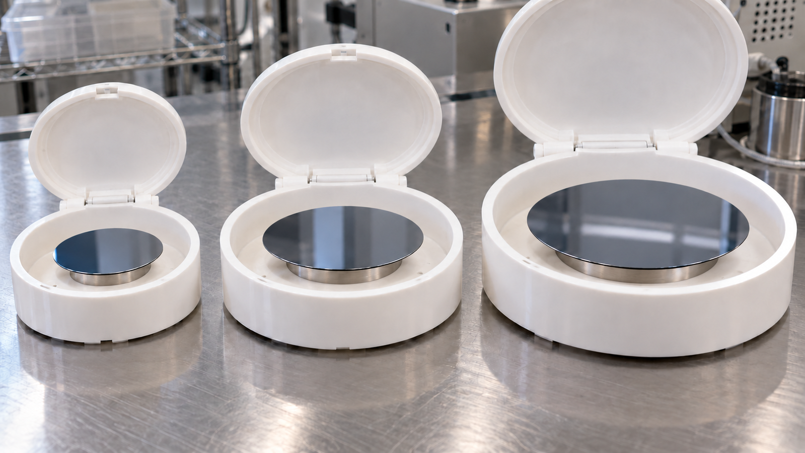
The substrate filter has three parts: the largest substrate, the smallest piece and the shape. The specifications fall into four groups:
- Up to 4-inch round. The EZ4-S has a maximum recommended spin coating diameter of 4-inch round substrates, with standard vacuum chucks of 10 mm, 25 mm and 2-inch.
- Chucks listed, maximum not specified. The EZ6-S and AC100-S come with 10 mm, 25 mm and 2-inch chucks; maximum substrate size is not specified. Uniformity data are given for the EZ6-S with 4-inch and 6-inch wafers.
- Fragments to 8-inch. The four AC200 configurations handle fragments to 8-inch wafers; the listed substrate range differs by configuration. The AC200-PE is the only configuration with standard vacuum trays up to 6-inch.
- Fragments to 12-inch. The AC300-S-CTM and AC300-S-EN handle fragments smaller than 1 cm to standard wafers up to 12 inches (300 mm), with custom solutions for larger or heavy-duty substrates.
The heated models are described separately: the IC5000-S uses an adjustable jaw chuck stage for 10–35 mm square or circular substrates, and the IC8000-S takes glass fragments and substrates and 6-inch glass or semiconductor wafers.
Shape, thickness and weight
Size limits usually refer to round wafers. Square glass, rectangles and fragments behave differently: corners travel on a larger radius, and a small piece may overhang or underhang a round chuck. A dedicated article, Spin Coating Small, Square and Fragment Substrates: Chucks, Vacuum and Corners, covers these substrates. No substrate thickness limit is specified for any Levon™ spin coater, so thick, heavy or very thin substrates should be described in the quote request.
Vacuum supply
Vacuum chucks need a vacuum source. The AC100-S, AC200-SE-PLUS, AC300-S-CTM and AC300-S-EN require a vacuum input of 0.06–0.09 MPa with a minimum flow rate above 15 L/min, and the AC200-S-PP a minimum vacuum flow rate of 15 L/min or more. For the other models a vacuum requirement is not specified; for every model, external utilities, where required, are supplied by the user.
5. Glovebox fit and footprint
Air- and moisture-sensitive inks, such as many perovskite precursors and organic semiconductors, are often coated in an inert-gas glovebox. That makes glovebox fit a hard filter for many labs. In the Levon™ spin coater range, two specifications cover it:
- The EZ4-S / EZ4-S-PP has a compact, glovebox-compatible design (EZ4-S 210 × 285 × 220 mm; EZ4-S-PP 215 × 285 × 222 mm, W × D × H).
- All four AC200 configurations can be recessed into a glovebox to reduce the operating height.
Glovebox use is not specified for the EZ6-S, AC100-S, AC300-S-CTM, AC300-S-EN, IC5000-S and IC8000-S. That does not mean they cannot be used in one, only that it must be confirmed. The IC8000-S is built as a separate spin chamber and control box, which changes how it would be arranged in any enclosure.
Before choosing, measure the antechamber opening and length, the working height and lid clearance inside the box, and the feedthroughs for power, vacuum and any dispensing lines. Spin coating also releases solvent vapor, so check how your purifier and solvent trap handle it. Dimensions of every model are in Table B.
6. Recipe control and timing
A spin recipe is a sequence of steps, each with a target speed, a ramp and a time. A typical program has spread, thinning and sometimes drying or edge steps. Program memories range from 5 programs × 5 steps on the EZ4-S to 100 recipes with up to 100 steps on the AC100-S, the AC200 configurations with a specified count, and the IC5000-S and IC8000-S. Program count is not specified for the AC200-SE-PLUS, AC300-S-CTM and AC300-S-EN.
Program memory matters most when several users or inks share one coater. Timing matters for short spread steps: every model has a maximum step or spin time of 3,000 s, set in 0.1 s increments on most models and 1 s on the EZ4-S. Control interfaces also differ, from an LCD text display with a membrane keypad on the EZ4-S to 7-inch touchscreens on the EZ6-S, AC200 and AC300. The AC100-S has a real-time parameter display with traceable process steps.
7. Dispensing, edge options and chamber materials
Most lab spin coating uses a pipette or syringe, before the spin starts (static dispense) or onto the spinning substrate (dynamic dispense). A dedicated article, Static vs Dynamic Dispense in Spin Coating: Volume, Coverage and Material Waste, compares the two methods. Automated dispensing helps when a recipe runs many times, when the dispense must be timed within a step, or inside a glovebox. Options:
- Integrated dispensing ports. The AC200-S-PP, AC200-SE and AC200-PE have integrated four-channel automatic dispensing ports, upgradeable to multi-channel.
- Dispensing upgrade. The EZ6-S offers an upgradeable single-channel precision metering dispensing system, and the IC5000-S and IC8000-S a precise metering automatic dispensing function.
- Edge and backside. The AC200-S-PP has integrated backside cleaning and edge debonding. On the AC200-SE, AC200-PE, AC200-SE-PLUS, AC300-S-CTM and AC300-S-EN, backside rinse (BSR) and edge bead removal (EBR) can be added. An edge bead, a raised rim of film, forms especially with thick films and square substrates [5]; defects are covered in Spin Coating Defects: Comets, Striations, Pinholes and Edge Beads Diagnosed.
Dispensing is not specified for the EZ4-S, AC100-S, AC200-SE-PLUS, AC300-S-CTM and AC300-S-EN.
Chamber and housing materials
Housing and chamber materials are a PP housing (EZ4-S-PP, AC200-S-PP), HDPE process chambers or cups (AC200-SE, AC200-PE, AC200-SE-PLUS, IC5000-S, IC8000-S), a PTFE-coated stainless steel chamber (AC300-S-CTM) and a stainless steel housing (AC300-S-EN; confirm the inner-cavity construction). Compatibility with a particular solvent or resist cannot be inferred from the material name alone; confirm it for aggressive chemistries.
8. When you need a heated spin table
Substrate temperature changes solvent evaporation and viscosity during spinning, and so it changes the thickness and the drying of the film [3]. Some processes, for example certain perovskite and polymer films, are coated on a warm substrate for that reason. A heated spin table controls table temperature; substrate and film temperatures may differ.
Two Levon™ models have a heated spin table. The IC5000-S heats from RT to 150 °C, spins at 100–5,000 rpm and holds 10–35 mm square or circular substrates. The IC8000-S heats from RT to 200 °C, spins at 100–8,000 rpm and takes glass fragments and substrates and 6-inch glass or semiconductor wafers. Both are specified with a temperature control accuracy of ≤±0.5 °C after stabilization and a spin table temperature uniformity of ≤±2%. A numeric value for RT and any cooling are not specified for either. A dedicated article, Heated Spin Coating: How Substrate Temperature Changes Evaporation and Thickness, covers heated spin coating.
9. Selection tables: specifications
The two tables compare the Levon™ spin coater range. Values belong to the model or configuration named and are not interchangeable. A dash means the specification is not listed; it does not mean the feature is absent.
Table A: speed, acceleration and recipe control
| Model | Speed | Speed resolution | Acceleration | Programs | Max. step / spin time |
|---|---|---|---|---|---|
| EZ4-S / EZ4-S-PP | 100–9,999 rpm | 1 rpm | 100–9,999 rpm/s | Up to 5 programs × 5 steps | 3,000 s; 1 s resolution |
| EZ6-S | 100–12,000 rpm | 1 rpm | 100–30,000 rpm/s | 10 programs × 10 steps | 3,000 s; 0.1 s resolution |
| AC100-S | Max. 12,000 rpm (no load) | 1 rpm | Max. 30,000 rpm/s | 100 recipes, up to 100 steps per recipe | 3,000 s; 0.1 s resolution |
| AC200-S-PP | 20–10,000 rpm | 1 rpm | 20–50,000 rpm/s | 100 recipes with 100 steps each; expandable | 3,000 s; 0.1 s resolution |
| AC200-SE | 20–10,000 rpm (no load) | 1 rpm | 20–50,000 rpm/s (no load) | 100 groups of 100 steps; more can be extended | 0–3,000 s/step; 0.1 s |
| AC200-PE | Max. 10,000 rpm (no load) | 1 rpm | Max. 50,000 rpm/s (no load) | 100 recipes with 100 steps each; more can be extended | 0–3,000 s/step; 0.1 s |
| AC200-SE-PLUS | Max. 8,000 rpm (no load) | ±1 rpm | Max. 10,000 rpm/s (no load) | — | 3,000 s; 0.1 s resolution |
| AC300-S-CTM | Max. 5,000 rpm (no load) | ±1 rpm | Max. 10,000 rpm/s (no load) | — | 3,000 s; 0.1 s resolution |
| AC300-S-EN | Max. 5,000 rpm (no load) | ±1 rpm | Max. 1,000 rpm/s (no load) | — | 3,000 s; 0.1 s resolution |
| IC5000-S | 100–5,000 rpm | 1 rpm | 100–5,000 rpm/s | Up to 100 recipes of 100-step programs; expandable | 3,000 s; 0.1 s resolution |
| IC8000-S | 100–8,000 rpm | 1 rpm | 100–5,000 rpm/s | Up to 100 recipes of 100-step programs; expandable | 3,000 s; 0.1 s resolution |
Table B: substrates, glovebox, footprint and options
| Model | Substrates | Chucks / trays | Glovebox | Dimensions (W × D × H) | Dispensing / edge options |
|---|---|---|---|---|---|
| EZ4-S / EZ4-S-PP | Max. recommended 4-inch round | Vacuum: 10 mm, 25 mm, 2-inch | Glovebox-compatible design | 210 × 285 × 220 mm / 215 × 285 × 222 mm | — |
| EZ6-S | Max. size not specified | 10 mm, 25 mm, 2-inch | — | 295 × 386 × 250 mm | Single-channel dispensing upgrade |
| AC100-S | Max. size not specified | 10 mm, 25 mm, 2-inch diameter | — | 340 × 410 × 385 mm | — |
| AC200-S-PP | 1 cm debris to max. 8-inch standard wafers | 10 mm, 25 mm, 2-inch | Can be recessed into a glovebox | 385 × 540 × 300 mm | Integrated 4-channel auto-dispensing ports; integrated backside cleaning and edge debonding |
| AC200-SE | Fragments to 8-inch circular wafers | Available: 10 mm, 25 mm, 2-inch | Can be recessed into a glovebox | 412 × 510 × 295 mm | Four-way automatic dispensing port; BSR and EBR can be added |
| AC200-PE | Fragments smaller than 1 cm to 8-inch circular substrates | 10 mm, 25 mm, 2-inch, 4-inch or 6-inch | Can be recessed into a glovebox | 415 × 500 × 300 mm | Four-way automatic dispensing port; BSR and EBR can be added |
| AC200-SE-PLUS | Fragments smaller than 1 cm to max. 8-inch standard wafers | — | Can be recessed into a glovebox | 598 × 556 × 286 mm | Dispensing not specified; BSR and EBR can be added |
| AC300-S-CTM | Fragments smaller than 1 cm to standard wafers up to 12 inches | — | — | 715 × 610 × 295 mm | Dispensing not specified; BSR and EBR can be added |
| AC300-S-EN | Fragments smaller than 1 cm to standard wafers up to 12 inches | — | — | 707 × 596.5 × 273 mm | Dispensing not specified; BSR and EBR can be added |
| IC5000-S | 10–35 mm square or circular | Adjustable jaw chuck stage | — | 268 × 340 × 255 mm | Automatic dispensing upgrade |
| IC8000-S | Glass fragments/substrates and 6-inch glass or semiconductor wafers | — | — | Spin chamber 260 × 500 × 350 mm; control box 310 × 420 × 200 mm | Automatic dispensing upgrade |
Source: ACS Material product specifications (October 2026). No-load values are hardware limits, not process results. Heating is specified only for the IC5000-S (spin table RT to 150 °C) and IC8000-S (RT to 200 °C). Substrate thickness limit: not specified. Final configurations are confirmed at quotation; the full range is on the Levon™ spin coaters page.
10. Matching common lab situations
These shortlists follow from the tables. They are starting points, not recommendations for a specific process.
- Small pieces and wafers up to 4-inch, inside a glovebox. The EZ4-S / EZ4-S-PP is the only compact model with a specified glovebox-compatible design. The AC200 configurations can be recessed into a glovebox if you need more programs, faster ramps or larger wafers.
- Benchtop work in air, programmable recipes and steep ramps. The EZ6-S (10 programs × 10 steps, 100–30,000 rpm/s) and the AC100-S (100 recipes, max. 30,000 rpm/s) cover this. Maximum substrate size is not specified for either; confirm your substrate and chuck combination.
- Wafers up to 8-inch, automated dispensing or edge cleaning. The AC200 family; compare the four configurations for speed, trays, dispensing and options.
- Wafers up to 12-inch or heavy substrates. The AC300-S-CTM and AC300-S-EN. They share the substrate range and speed but differ in maximum acceleration (10,000 versus 1,000 rpm/s, no load).
- Substrate heated during spinning. The IC5000-S for 10–35 mm pieces with table heating to 150 °C, or the IC8000-S for 6-inch wafers with table heating to 200 °C.
Some combinations are not covered by any single model: for example, a 6-inch wafer heated during spinning inside a glovebox. The IC8000-S covers the size and the heating, but glovebox use is not specified. In such cases, list all requirements in one request so they can be checked together.
11. Checklist before you request a quote
- Substrates: material, shape, largest and smallest size, thickness and weight, and whether they are textured or fragile.
- Recipes: lowest and highest speed, steepest and gentlest ramp, longest and shortest step, and number of steps per recipe.
- Users and recipes: how many people and inks share the coater, and how many recipes must be stored.
- Environment: air or glovebox, antechamber size, working height, exhaust and solvent handling.
- Utilities: mains voltage, vacuum source and flow, and any nitrogen supply.
- Options: automatic dispensing, edge bead removal, backside rinse and heated spin table.
- Chemistry: solvents and resists you will use, especially aggressive ones.
- Measurement: how you will check thickness and uniformity after installation.
Send this information through the contact form or the Get Quote request on the product page.
12. Keep Exploring the Spin Coating Knowledge Hub
This guide is the equipment hub of the spin coating section of the ACS Material thin-film library.
Start here
- Spin Coating Explained: Stages, Physics and Film Thickness — the four stages of spin coating, the thickness models and the main defects.
- Solution-Processed Thin Films: Choosing Spin, Dip, Slot-Die or Blade Coating — when spin coating is the right method, with the interactive coating method selector.
Spin coating process guides
- Spin Speed vs Film Thickness: How to Build and Use a Spin Curve — turning a few measured points into a speed–thickness curve.
- Spin Coating Acceleration and Multi-Step Recipes: What the Ramp Actually Does — what the ramp does to spreading, coverage and thickness.
- Static vs Dynamic Dispense in Spin Coating: Volume, Coverage and Material Waste — dispense methods, volume and material waste.
- Spin Coating Defects: Comets, Striations, Pinholes and Edge Beads Diagnosed — causes and fixes for common film defects.
- Spin Coating Small, Square and Fragment Substrates: Chucks, Vacuum and Corners — chucks, vacuum and corner effects.
- Heated Spin Coating: How Substrate Temperature Changes Evaporation and Thickness — how substrate temperature changes evaporation and thickness.
Spin coating equipment
- Levon™ spin coaters — compact, programmable, servo and heated spin coaters.
- EZ4-S compact spin coater, EZ6-S benchtop spin coater and AC100-S programmable spin coater — compact and benchtop coaters for small pieces and wafers.
- AC200 programmable servo spin coater, AC300-S-CTM and AC300-S-EN servo spin coaters — servo-driven coaters for wafers up to 8 and 12 inches.
- IC5000-S and IC8000-S heated spin coaters — programmable recipes with a heated spin table.
13. FAQ
What should I look for in a spin coater for a lab?
Start with the substrate size and shape, glovebox use and heating, because these remove the most models. Then check that the speed and acceleration ranges cover your recipes with margin, and that program memory, timing resolution and dispensing or edge options match your users and process.
How fast does a lab spin coater need to spin?
Fast enough to reach your highest recipe speed with some margin; the right range depends on your ink and target thickness. Because thickness falls roughly with the square root of speed in the ideal model, extra top speed only modestly extends the thickness window, and a no-load maximum is a hardware limit, not a process result.
Which Levon™ spin coaters can be used in a glovebox?
The EZ4-S / EZ4-S-PP has a glovebox-compatible design, and all four AC200 configurations can be recessed into a glovebox. For the other models, glovebox use is not specified; confirm it before ordering, together with your antechamber size and working height.
Which spin coater handles 8-inch or 12-inch wafers?
The AC200 configurations handle fragments to 8-inch wafers. The AC300-S-CTM and AC300-S-EN handle fragments smaller than 1 cm to standard wafers up to 12 inches (300 mm), with custom solutions for larger substrates.
Do I need a heated spin coater?
Only if your process needs the substrate at a controlled temperature during spinning. Otherwise, a standard spin coater and a separate hot plate for baking are usually enough. The IC5000-S and IC8000-S have heated spin tables up to 150 and 200 °C.