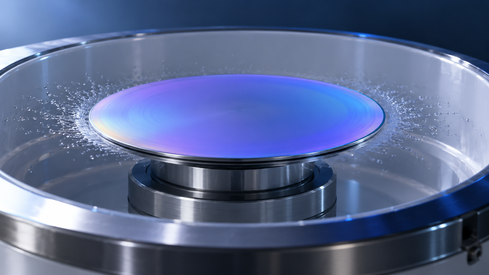
A small pool of solution lands on a wafer, the motor ramps up, and a few seconds later the liquid has become a film a micrometre or less thick, often with a thickness variation small enough to need an instrument to measure. Spin coating looks like a single step, but the film passes through four stages, and two different physical models describe how it thins. This guide explains the stages, the classic Emslie–Bonner–Peck and Meyerhofer models, what each one predicts about film thickness, where each one stops being valid, and how to turn the theory into a spin curve for your own ink. It ends with the settings that matter on a spin coater and the Levon™ spin coaters from ACS Material, using only the specifications published on their product pages.
In one paragraph: spin coating runs through deposition, spin-up, spin-off (flow-dominated thinning) and evaporation-dominated thinning. The Emslie–Bonner–Peck model (1958) describes spin-off for a Newtonian liquid without evaporation: an initially flat film stays flat, thins with time and soon forgets its starting thickness. Meyerhofer's model (1978) adds evaporation and explains why the final film depends on speed, viscosity and evaporation rate; in its ideal form thickness falls as the inverse square root of spin speed. Both models assume a flat, round, axisymmetric substrate and a well-behaved liquid. Non-Newtonian inks, skin formation, fingering, striations and square substrates fall outside them, so the working curve for a real ink comes from a measured speed series.
1. The short answer: what sets the thickness
In a typical spin-coating process, enough liquid is dispensed to cover the substrate before most of the excess is expelled over the edge. Two mechanisms thin the film. First, rotation drives radial outflow, carrying liquid toward and over the edge. As the film becomes thinner, this flow slows sharply because viscous resistance becomes increasingly important. Second, solvent evaporates from the free surface. As solvent leaves, the nonvolatile components become more concentrated, viscosity can rise, and the remaining film eventually becomes too viscous to flow appreciably. The film then continues to dry in place. Final thickness depends on the ink formulation, spin program, substrate and drying conditions—not simply on the volume dispensed.
That sequence explains the practical rules most labs learn by experience:
- Spin speed is the main dial during a run. Faster rotation removes more liquid before the film sets, so the film is thinner; in the ideal evaporation-controlled model, thickness scales as the inverse square root of speed.2
- The ink decides the scale: its viscosity, its solids content and the volatility of its solvent. How strongly each of these moves the film on a given ink is measured, not assumed.
- The dispensed volume matters mainly for covering the substrate. Once the substrate is covered, the flow-only model predicts that the film largely loses its dependence on its starting thickness; coverage, wetting and edge behaviour still depend on how much is dispensed.1
- Spin time matters until the film has set; after that, further spinning mainly finishes the drying.
- A round substrate is what the theory assumes. Squares, rectangles and edges behave differently.
If you are still choosing between spin coating and other solution methods, start with the guide to choosing spin, dip, slot-die or blade coating, which includes an interactive coating method selector. This article goes one level deeper into spin coating itself.
2. The four stages of spin coating
Descriptions of the spin coating process usually divide it into four stages.4,5 They overlap in time, especially the last two, but each has a different dominant physics and a different typical defect.
| Stage | What happens | What controls it | Typical problem if it goes wrong |
|---|---|---|---|
| 1. Deposition | Liquid is dispensed onto the substrate, at rest or turning slowly, and wets part or all of it | Dispense volume and position, wetting of the surface, cleanliness | Uncoated areas from poor wetting; bubbles; comets from particles |
| 2. Spin-up | The substrate accelerates to its final speed; the liquid spreads outward and starts to rotate with the substrate | Acceleration, viscosity, how much of the surface was already wetted | Spiral or radial fingering at the advancing front; incomplete coverage |
| 3. Spin-off (flow-dominated) | The liquid rotates with the substrate and thins by radial outflow; excess liquid leaves over the edge as droplets | Speed, viscosity, density, time | Edge bead; non-uniformity if the liquid is not Newtonian |
| 4. Evaporation-dominated | Outflow has become slow; the film thins mainly by losing solvent until it sets | Evaporation rate (solvent volatility, air flow over the surface, vapour around the substrate), solids content | Striations, skin formation, haze, sensitivity to the local atmosphere |
Two points follow from this table. First, the stages that set the thickness are the last two; deposition and spin-up mainly decide whether the film is complete and defect-free. Second, the physics changes as the film thins. A model built for stage 3 cannot by itself predict the final thickness, because the film spends its last and most decisive moments in stage 4. That is exactly the difference between the two classic models below.
3. Spin-off: the Emslie–Bonner–Peck model
In 1958, Emslie, Bonner and Peck analysed a Newtonian liquid on a flat disc that rotates at constant angular velocity.1 In the rotating frame, centrifugal force pushes each element of liquid outward and viscous shear against the disc holds it back. For a thin layer, the balance gives a radial velocity profile that grows with height above the disc, and a mass balance then gives how the film thickness changes with time. For a film that starts uniform, the solution is:
h0 = initial thickness; ρ = density; ω = angular velocity (rad/s); η = viscosity; t = spinning time
Assumptions: a thin Newtonian liquid layer on a flat, horizontal, axisymmetric rotating disc; constant angular velocity after spin-up; negligible solvent evaporation, gravity and edge effects; and the idealized radial flow and viscous-shear balance used in the model. The equation describes flow-driven thinning, not the final dry thickness of a real solution film.
Three results make this model useful.
- A uniform film stays uniform. The radial flow grows in proportion to the radius, so the net loss of liquid per unit area is the same at every radius and a flat film thins as a flat film. Emslie and co-workers also showed that an uneven initial layer tends toward uniformity as it thins.1
- The starting thickness is soon forgotten. Once the second term under the root is much larger than 1, the solution approaches h ≈ √[3η ÷ (4ρω2t)], which contains no h0. Within this model, once the second term under the root dominates, the predicted thickness becomes approximately independent of the initial thickness. This describes the flow-only idealization; it does not establish that dispense volume is irrelevant to coverage or that the same relationship holds through solvent evaporation and film solidification.
- Thinning slows down. At long times the film thins only as t−1/2. Doubling the spin time does not halve the film; it reduces it by a factor of about 1.4.
h0 = 50 µm → h ≈ 4.12 µm; h0 = 100 µm → h ≈ 4.13 µm (wet film, no evaporation)
same liquid at 4,000 rpm, 10 s → h ≈ 2.07 µm; at 2,000 rpm, 30 s → h ≈ 2.39 µm
Doubling the starting thickness changes the result by less than 0.3 %. Notice also what the model says about speed: at a fixed time, the flow-only result falls as ω−1, so doubling the speed halves the film. That is a steeper dependence than spin coaters show in practice for solutions; a photoresist supplier's application note, for example, gives film thickness as falling approximately with the inverse square root of speed.9 The reason is the missing ingredient: evaporation.
The model has a second limit. Because it contains no evaporation, it never stops; in theory the film keeps thinning forever. A real solution film stops flowing when enough solvent has left it. The Emslie–Bonner–Peck model therefore describes stage 3 well and says nothing about where stage 4 ends.
4. Evaporation: the Meyerhofer model
Twenty years later, Meyerhofer added solvent evaporation to the picture, using positive photoresists as the test case.2 His model keeps only the centrifugal force, linear shear and a uniform evaporation rate, and splits the process in two. At first the film thins by flow at constant concentration, as in the Emslie–Bonner–Peck model. Flow thinning slows as the film gets thinner, while evaporation goes on at a roughly constant rate. The model switches from the first stage to the second at the moment the two rates are equal: from then on, flow is neglected and the film loses only solvent until it is dry. The solids present in the film at the switch point make up the final film.
Working through that switch point gives a compact result for the final thickness:
f = spin speed; η0 = initial dynamic viscosity; e = solvent evaporation rate. The proportionality constants depend on the model assumptions and the units used.
assumptions: Newtonian flow until the film sets, uniform evaporation, flat round substrate, fixed initial solids content and density; ideal exponent, not a fit to any particular ink
ideal-model example: 1,000 → 4,000 rpm, thickness falls by √4 = 2×; 2,000 → 3,000 rpm, by about 18 %
In Meyerhofer's model, the solvent evaporation rate is assumed to increase with spin speed; for the model's stated conditions, it is taken to be proportional to the square root of speed.2 Substituting this relationship into the preceding expression changes the ideal speed dependence from f−2/3 to f−1/2. Under these assumptions, a fourfold increase in speed halves the predicted final thickness. This is a useful theoretical reference, not a universal law for every ink or coater. The exponent for a particular ink should be determined from measurements made with the other recipe conditions held fixed. In his photoresist experiments, Meyerhofer also found that, when adequate care is taken, the liquid forms a level surface during spinning; the film is then uniform and its thickness does not depend on the size of the substrate.2
Two further consequences are worth stating plainly:
- Viscosity enters only weakly. In the ideal model, thickness grows with the cube root of the initial dynamic viscosity, η0. Doubling the viscosity raises the film by about 26 % in that model, everything else equal.
- The solids content converts wet to dry. The model's switch point fixes a wet film; the dry film is what its solids leave behind. If all solids stay in place, hdry = hwet × φs ÷ (1 − P), where φs is the solids volume fraction at the switch point and P the porosity of the dry film. For example (assumed values), if the wet layer at the switch point is 4.1 µm thick and holds 2 % solids by volume, it leaves about 82 nm of dense film. Raising the concentration also raises the viscosity, so concentration moves the film through two routes at once; how much, for a given ink, is again found with a series.
Later work refined the picture without overturning it. Bornside, Macosko and Scriven solved the coupled flow, evaporation and diffusion problem across the film thickness, with viscosity and diffusivity that depend on concentration.5 Hall, Underhill and Torkelson compared a simple model proposed by Bornside, Macosko and Scriven, which treats flow and evaporation separately, with measured polymer films from about 10 nm to 33 µm thick, in solvents of different volatility; the model predicted thickness within 10 % over their conditions, and the deviations were systematic: it underpredicted with very volatile solvents or high polymer concentrations and overpredicted with low-volatility solvents or very low concentrations.7 Those are their results for their polymer solutions; they show both how far the simple picture goes and the direction in which it fails.
5. Where the models fail
Both classic models rest on a short list of assumptions. Each assumption corresponds to a family of real situations where the prediction stops working, often in a recognisable way.
| Assumption | When it breaks | What you see | Model affected |
|---|---|---|---|
| Newtonian liquid | Shear-thinning or viscoelastic inks: concentrated polymer solutions, flake and nanowire dispersions, pastes | For a power-law liquid, even an initially uniform film is deformed by rotation3 | Both |
| Flow and evaporation can be treated separately | Fast-drying solvents; solutions whose viscosity rises steeply as solvent leaves | A concentrated, viscous surface layer (skin) can form while the liquid below still flows5; thickness off the simple prediction in a consistent direction7 | Meyerhofer |
| Uniform evaporation and surface tension | Solvent mixtures or solvents whose loss raises the surface tension at the surface | Striations: radial thickness ridges driven by surface-tension gradients8 | Both |
| A film already covering the substrate | Spreading from a drop during spin-up, especially on poorly wetting surfaces | Fingers or rivulets at the advancing front; their onset depends on the wetting properties of the liquid6 | Both (they start from a film) |
| Flat, round, axisymmetric substrate | Squares and rectangles | Edge and corner buildup; the axisymmetric solution does not predict the thickness distribution9 | Both |
| No edge effects | The rim of the substrate, where flow and drying conditions differ from the interior | A thicker rim (edge bead), which is why some coaters offer edge bead removal9 | Both |
Non-Newtonian inks
Acrivos, Shah and Petersen extended the rotating-disc analysis to power-law liquids in 1960. Their conclusion is the clearest warning in the spin coating literature: for a Newtonian liquid, centrifugation smooths out irregularities in the surface, but for a non-Newtonian liquid even an initially uniform film is deformed as the disc turns.3 Inks that thin under shear — many polymer solutions and dispersions of flakes or wires — are therefore less forgiving, and their spin curves deserve more points and repeat runs.
Fingering, striations and skins
Three more failure modes are listed in the table above and need only a short note here. A puddle that spreads during spin-up can break into fingers before the substrate is covered, and the onset depends on the wetting properties of the liquid.6 Surface-tension gradients created as solvent evaporates can leave radial striations, and solvent choice can suppress them.8 If the surface dries much faster than solvent can diffuse up from below, a viscous skin can form on still-fluid liquid.5 Diagnosing and fixing these defects is a topic of its own and is not covered in depth here.
Square substrates and edges
The classic models assume a flat, axisymmetric disc and do not predict the thickness distribution on square or rectangular substrates. In practice, non-circular substrates can show edge and corner buildup because the flow, airflow and evaporation conditions near their boundaries differ from those over the interior.9 The magnitude and location of the buildup depend on the substrate geometry, chuck and airflow configuration, ink or resist, and recipe. Treat this as a common failure mode rather than a universal geometric rule. If the active area approaches an edge, measure the film where it matters, leave a suitable margin, or evaluate a carrier-chuck or other edge-control approach.
6. From theory to a spin curve
The models above tell you the shape to expect; a spin curve gives the numbers for your ink. A spin curve is simply film thickness measured against final spin speed, with everything else held fixed: the same ink batch, dispense, acceleration, spin time, substrate, cleaning, ambient conditions and bake. Plotted on log–log axes, a well-behaved ink gives a roughly straight line whose slope is the exponent.
How many points you need
- One measured point does not measure an exponent. You can scale the ideal curve through it — keep the exponent fixed at −1/2 and calibrate only the prefactor — but the result is an assumption-based estimate, and it should be labelled as one.
- Two points are enough to solve for both the exponent and the prefactor, but they say nothing about scatter. Any error in either point goes straight into the exponent.
- Three or more points, ideally with repeats at each speed, allow a proper fit with an uncertainty. Keep two uncertainties apart: how well the fitted line is known (fit uncertainty), and how far a single new film may land from it (prediction uncertainty, which includes run-to-run scatter). For setting a recipe, the second is the one that matters.
Stay inside the measured speed range. Outside it the exponent can change, especially at low speeds where the film may set before spin-off is finished, and at the high end the motor is not a guarantee of anything: a coater's maximum speed is a hardware limit, usually quoted without load, not a promise of a minimum thickness.
To fit your own measurements, use the spin curve fitter below. It opens with example values, not measured data; replace them with your own films. It states what the number of speeds can support and gives a speed only inside the measured range. For the full method, from choosing speeds to reading the fit, see how to build a spin curve.
What to change, and in what order
- Coarse adjustment: review the ink formulation and process conditions. If the film is far from the target, first determine whether the gap is caused by solids content, viscosity, solvent evaporation, wetting, or the spin program. Changing concentration can shift the final thickness substantially, but it also changes viscosity and drying behaviour. Change one controlled variable at a time, then measure again.
- Fine scale: the speed. Use the measured spin curve to choose a final speed within the calibrated range, keeping the other recipe conditions fixed.
- Time: long enough for the film to set at the final speed. A run that ends too early leaves a wet film that keeps flowing while the substrate slows down.
- Coverage: dispense and the first step. If the substrate is not fully covered, adjust the dispense volume, the dispense step and the acceleration, not the final speed.
- Atmosphere: if results drift from day to day, look at solvent vapour, air flow and temperature around the substrate before changing the recipe.
For the substrate preparation, baking and measurement steps around the coater, see the workflow section of the coating methods guide.
7. Spin coater settings and Levon™ models
The physics points to the settings that matter on a spin coater: the speed range and how finely it can be set, the acceleration, the step time, the number of program steps (a dispense or spread step, a thinning step, a drying step), the substrate sizes the chucks accept, and the environment around the substrate. The table below lists these values as published on the Levon™ spin coater pages. Values belong to the model or configuration named; they are not interchangeable.
| Model | Speed | Acceleration | Programs / step time | Substrates |
|---|---|---|---|---|
| EZ4-S / EZ4-S-PP | 100–9,999 rpm, 1 rpm resolution | 100–9,999 rpm/s | 5 programs × 5 steps; up to 3,000 s per step, 1 s resolution | Round substrates up to 4-inch recommended; chucks 10 mm, 25 mm, 2-inch; glovebox-compatible |
| EZ6-S | 100–12,000 rpm | 100–30,000 rpm/s | 10 programs × 10 steps; up to 3,000 s, 0.1 s resolution | Chucks 10 mm, 25 mm, 2-inch; largest substrate not stated |
| AC100-S | Up to 12,000 rpm (no load) | Up to 30,000 rpm/s | 100 recipes × up to 100 steps; up to 3,000 s per step, 0.1 s resolution | Chucks 10 mm, 25 mm, 2-inch; largest substrate not stated |
| AC200-S-PP / AC200-SE | 20–10,000 rpm (SE: no load) | 20–50,000 rpm/s (SE: no load) | 100 recipes × up to 100 steps; up to 3,000 s per step, 0.1 s resolution | Fragments to 8-inch wafers; can be recessed into a glovebox |
| AC200-PE / AC200-SE-PLUS | Max. 10,000 rpm / max. 8,000 rpm (no load) | Max. 50,000 rpm/s / max. 10,000 rpm/s (no load) | PE: 100 recipes × up to 100 steps; SE-PLUS: recipe count not stated; up to 3,000 s per step, 0.1 s resolution | Fragments to 8-inch; can be recessed into a glovebox |
| AC300-S-CTM / AC300-S-EN | Up to 5,000 rpm (no load) | Up to 10,000 rpm/s / up to 1,000 rpm/s (no load) | Up to 3,000 s rotation time, 0.1 s resolution; recipe count not stated | Fragments smaller than 1 cm to 12-inch (300 mm nominal) wafers |
| IC5000-S (heated) | 100–5,000 rpm | 100–5,000 rpm/s | Up to 100 recipes of 100-step programs; up to 3,000 s per step, 0.1 s resolution | Jaw chuck for 10–35 mm square or round substrates; spin table RT to 150 °C |
| IC8000-S (heated) | 100–8,000 rpm | 100–5,000 rpm/s | Up to 100 recipes of 100-step programs; up to 3,000 s per step, 0.1 s resolution | Glass pieces to 6-inch glass or semiconductor wafers; spin table RT to 200 °C |
Values from the Levon™ product pages as listed on 22 October 2026. “No load” speeds and accelerations are hardware limits, not process results. None of the pages states a substrate-thickness limit for the chuck. The full range is on the Levon™ spin coaters page.
How the specifications map to the physics
- Speed range and resolution set where on your spin curve you can work. The ideal model's square-root dependence means that a small speed change moves the film only a little, which is useful for fine trimming; the range limits are hardware values, not thickness limits.
- Acceleration governs spin-up: how quickly the dispensed liquid is brought to the final speed. It matters most for coverage and fingering, and it should be held fixed within a spin curve.
- Program steps allow a low-speed spread step before the thinning step and a drying step after it. The EZ4-S stores 5 programs of 5 steps, the EZ6-S 10 × 10, and the AC100-S, IC5000-S, IC8000-S, AC200-S-PP, AC200-SE and AC200-PE 100 recipes of up to 100 steps; the AC200-SE-PLUS page does not state a recipe count.
- Dispensing affects deposition and repeatability. The EZ6-S page lists an upgradeable single-channel precision metering dispenser; the AC200-S-PP lists integrated four-channel automatic dispensing ports, and the AC200-SE and AC200-PE list four-way automatic dispensing ports; all three are upgradeable to multi-channel dispensing (no dispensing port is listed for the AC200-SE-PLUS).
- Edge treatment addresses the edge bead. The AC200-S-PP page lists integrated backside cleaning and edge debonding; for the AC200-SE, AC200-PE and AC200-SE-PLUS, backside rinse (BSR) and edge bead removal (EBR) can be added as options.
- Heated spin tables on the IC5000-S and IC8000-S change stage 4 directly, because temperature changes the evaporation rate; a spin curve measured at one table temperature does not transfer to another.
- Glovebox operation changes the atmosphere above the film and therefore evaporation. The EZ4-S page describes it as suitable for glovebox setups, and all four AC200 configurations can be recessed into a glovebox; the EZ6-S, AC100-S, AC300-S, IC5000-S and IC8000-S pages do not mention glovebox use.
Reading published uniformity data
Several Levon™ pages publish film uniformity results. Each result belongs to a specific wafer size, film thickness and photoresist, and the pages do not state the spin speed used, so these values cannot be used to build or check a thickness–speed curve. They show what the stated combination achieved; they are not a promise for other inks or recipes.
- EZ6-S, 4-inch: within-wafer ±0.53 %, wafer-to-wafer ±1.09 %, for a 1,350 nm film of AZ1500 (20 cP).
- EZ6-S, 6-inch: within-wafer ±1.20 %, wafer-to-wafer ±1.89 %, for a 4,400 nm film of SPR220-4.5 (123 cP). The page states that the data apply only to these conditions.
- AC200-S-PP, AC200-SE and AC200-PE (not published for the AC200-SE-PLUS): 4-inch ±0.49 % / ±0.55 % (500 nm, RZJ304, <10 cP); 6-inch ±0.76 % / ±0.91 % (1,300 nm, AZ1500, 20 cP); 8-inch ±0.92 % / ±1.10 % (1,350 nm, AZ1500, 20 cP), within-wafer / wafer-to-wafer. The AC200-SE specifications also list a rotational coating uniformity of <±3 % within 6 inches, without stated conditions.
- AC300-S-CTM and AC300-S-EN (the same values on both pages): 4-inch ±0.65 % / ±0.22 % (1,470 nm); 6-inch ±0.76 % / ±0.91 % (1,320 nm); 8-inch ±0.62 % / ±1.39 % (2,260 nm); 12-inch ±1.16 % / ±0.70 % (490 nm), within-wafer / wafer-to-wafer, AZ1500 (20 cP; 4.4 cP for the 12-inch result).
All of the test results above that state their conditions were measured with photoresists. Positive photoresists are the liquids on which Meyerhofer tested his model, and he reported excellent agreement.2 Dispersions, shear-thinning polymer solutions and fast-drying inks depart further from the model's assumptions, so expect to measure their uniformity yourself.
Before you request a quote
- Substrate: shape, size and thickness, and whether fragments or squares must be held; the chucks or trays you need.
- Ink: solvent, viscosity if known, solids content, and whether it is a dispersion.
- Film: target thickness, the area that must be uniform, and whether edge bead removal or backside cleaning is needed.
- Process: speed range, number of steps, heated spin table and temperature, glovebox internal dimensions.
- Points the pages leave open: largest substrate on the EZ6-S and AC100-S, substrate-thickness limits, the recipe count on the AC200-SE-PLUS and AC300-S, and glovebox use for models other than the EZ4-S and AC200.
Send these through the contact form or the Get Quote request on the product page.
8. Knowledge hub
This article is the entry point to the spin coating section of the ACS Material thin-film library. Detailed articles on spin curves, recipes, defects and specific inks will be added here as they are published.
Start here
- Solution-Processed Thin Films: Choosing Spin, Dip, Slot-Die or Blade Coating — when spin coating is the right method, with the coating method selector.
Spin coating equipment
- Levon™ spin coaters — compact, programmable, servo and heated spin coaters from small pieces to 12-inch wafers.
- EZ4-S compact spin coater, EZ6-S benchtop spin coater and AC100-S programmable spin coater — small pieces and wafers in research labs.
- AC200 programmable servo spin coater, AC300-S-CTM and AC300-S-EN — servo-driven coaters to 8-inch and 12-inch wafers.
- IC5000-S and IC8000-S heated spin coaters — coating on a heated spin table.
Before and after the coater
- UV-ozone cleaners and plasma cleaners — cleaning and activation before coating.
- Hot plates — soft bake and anneal after coating.
- All Levon™ equipment.
9. FAQ
What are the stages of spin coating?
Deposition, spin-up, spin-off and evaporation-dominated thinning. In deposition the liquid is dispensed and wets the substrate; in spin-up the substrate accelerates and the liquid spreads; in spin-off the film thins by radial outflow and the excess leaves over the edge; in the last stage, outflow has slowed and the film thins mainly by losing solvent until it sets. The last two stages set the thickness.
What is the Emslie–Bonner–Peck equation?
It is the 1958 solution for a Newtonian liquid thinning on a rotating disc without evaporation: h(t) = h0 ÷ √[1 + 4ρω2h02t ÷ (3η)]. It shows that a uniform film stays uniform and that, after a short time, the thickness no longer depends on how thick the layer started. Because it has no evaporation, it does not predict where a real solution film stops thinning.
Why is film thickness often said to scale with the inverse square root of spin speed?
In Meyerhofer's model, the final thickness scales as f−2/3 times the cube root of the evaporation rate, and the evaporation rate is assumed to grow as the square root of speed. Together these give f−1/2. It is an ideal exponent: in that model four times the speed halves the film, but a real ink's exponent is measured with a speed series.
Does dispensing more solution make a thicker film?
Once a substrate is fully covered and the process is operating in a suitable regime, adding more solution often increases waste rather than final film thickness. The classic models predict that the film loses much of its dependence on its starting thickness during spin-off. In practice, dispense volume still matters for coverage, wetting, edge behaviour and repeatability, especially with difficult inks or non-circular substrates. Use enough material to achieve reliable coverage, then verify the result experimentally.
Can I make a thinner film just by spinning faster?
Increasing spin speed generally makes a spin-coated film thinner, but the relationship depends on the ink and the process conditions. The inverse-square-root relationship is an ideal-model result, not a guaranteed exponent for every formulation. Use a measured spin curve to select speeds within the tested range; our guide to spin speed vs film thickness shows how to build one. A coater's maximum speed is a hardware limit, often specified without load, and does not guarantee a particular minimum film thickness.
Why can the corners of a square substrate come out thicker?
The classic models assume an axisymmetric disc and cannot predict the full thickness distribution on a square or rectangular substrate. Edge and corner buildup can occur because the local flow, airflow and drying conditions differ from those over the interior. The extent depends on the substrate, chuck, ink and recipe. Measure the active area and, if needed, evaluate a suitable margin, carrier chuck or edge-control approach.
Why do I see radial stripes in my film?
Radial striations usually come from surface-tension gradients created as solvent evaporates. Whether they form depends on how the surface composition changes during drying; solvent choice, including solvent mixtures, can reduce or avoid them.