
Every rotary evaporation is the same five moves: inspect and charge the flask, connect cooling and let the bath and coolant settle, start rotation and lower the flask, ramp the vacuum while the condenser collects, then stop, lift, vent and remove. Each move looks like a button press and is actually a decision — about how much sample the flask can safely hold, how fast the pressure may fall, how thin the film becomes, how much heat the condenser must remove, and when to stop. Get one of the five wrong and the run does not merely go slowly; it bumps, loses volatiles, contaminates the pump, or leaves a residue that is not what you think it is. This guide walks the five steps in order and names, at each one, the physics that decides the outcome.
In one paragraph: Step 1 — inspect and charge to about half the flask volume; over-filling is a frequent self-inflicted cause of bumping and carry-over. Step 2 — connect cooling and stabilize the bath and coolant before evaporation begins, so every later observation is measured against a steady baseline. Step 3 — start rotation and lower the flask, establishing a thin, continuously renewed film before the pressure falls: rotation buys evaporating area, shortens the conduction path and can reduce localized superheating. Step 4 — ramp the vacuum and condense: the duty is latent heat, so water demands roughly three times the cooling of ethanol at the same volumetric rate, and vapor that escapes the condenser is lost material and a pump problem. Step 5 — stop, lift and vent: stop at the point of interest rather than at dryness, lift the flask clear of the bath before releasing vacuum, and never evaporate a peroxide-forming solvent to dryness — leave a heel of solvent and follow the current SDS and institutional procedure. For the system-level treatment of pressure, film formation, vacuum, cooling duty and solvent recovery, see the complete guide to rotary evaporation.
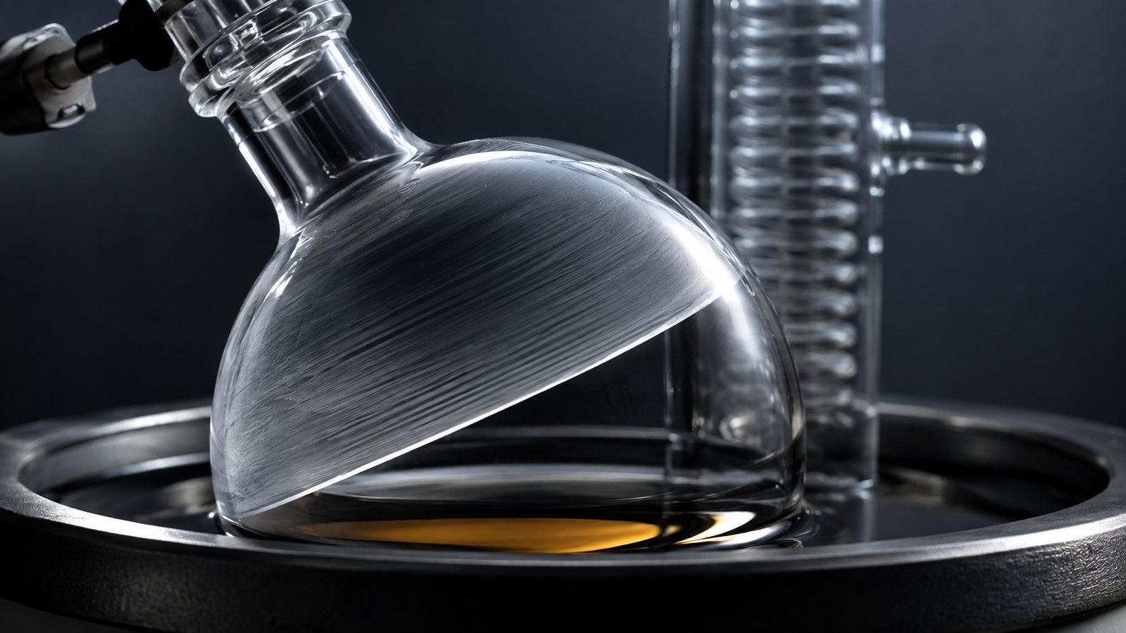
The five steps at a glance
Rotary evaporation is the most-performed separation in most laboratories, and it inherits its importance from a larger fact: thermally driven separations dominate the energy budget of chemistry, and a widely cited analysis in Nature placed chemical separations at roughly 10–15% of global energy consumption.1 At bench scale that translates into a simpler observation — solvent dominates the mass balance of almost every synthesis. Process mass intensity was adopted across the pharmaceutical industry precisely because it makes that dominance visible instead of hiding it inside yield figures,2 and the E-factor literature reaches the same conclusion from the waste side, with solvent the largest single contributor to the mass of waste per mass of product.3 The five steps below are how that solvent is put back where it came from.
| Step | What you are physically doing | What it decides |
|---|---|---|
| 1. Inspect and charge | Checking glassware and seal, filling the flask, seating the joint | Headspace for foaming; bumping risk; whether the seal holds |
| 2. Connect cooling and stabilize | Routing the coolant loop; bringing bath and coolant to setpoint | Whether later observations have a steady baseline; condenser readiness |
| 3. Start rotation and lower | Establishing a film, then immersing the flask | Evaporating area, heat-transfer path, nucleation behavior |
| 4. Ramp vacuum and condense | Lowering pressure gradually while the condenser collects | The boiling point; whether boiling starts smoothly; recovery and pump protection |
| 5. Stop, lift and vent | Ending the run, lifting clear of the bath, venting per the manual | Residue composition, thermal exposure, safety at the end |
Step 1 — Inspect and charge the flask
Fill to about half, and know why
The single most common self-inflicted problem in rotary evaporation begins here. A flask filled close to its nominal volume has no headspace to absorb the sudden expansion of a bumping event and no room for foam to rise and collapse before it reaches the vapor duct. Filling to roughly half the flask volume is the conventional compromise: enough charge to make the run worthwhile, enough headspace that a disturbance stays inside the flask.
There is a second reason that is easy to miss. Rotation works by dragging liquid up the wall into a film, and the thickness of that film depends on how much liquid is available relative to the wetted area. An over-filled flask does not form a thin film at all — it forms a sloshing pool with a thin skin above it, which is closer to a stirred flask than to a rotary evaporator, and which behaves accordingly when it boils.
Inspect before you seat the joint
A flask about to be evacuated is a pressure vessel with the pressure differential on the outside. Star cracks around the joint, scoring from a clamp, or a chip at the rim are the defects that turn a routine concentration into a glass failure, and they are found by looking rather than by hoping. The vacuum seal is the other consumable: seals can wear, score, deform or lose sealing performance with use and age, and a seal that leaks slightly does not announce itself — it simply makes every pressure setting on the datasheet fictional and every observation afterwards ambiguous.
- ALab™ RE100-S LED Digital Rotary Evaporator — 50–3000 mL flask range with manual plus auxiliary lift, 1200 cm² vertical condenser configuration, and a 5 L water/oil bath with independent control that can be used on its own.
- ALab™ RE100-Pro Digital Rotary Evaporator — the same flask range with a 150 mm motorized lift, 20–280 rpm drive and 1700 cm² condenser.
Step 2 — Connect cooling and stabilize
Bring the bath and the coolant to their setpoints and let them settle before evaporation begins. It costs a few minutes and removes a major source of run-to-run variability, because every parameter set afterwards is then measured against a steady baseline rather than a moving one. Route the coolant loop according to the condenser and circulator instructions, keep hose runs short and insulated for low-temperature work, and confirm flow before heating anything.
Two details repay attention here. A chiller’s capacity is specified at a stated coolant temperature, and the capacity available at your intended setpoint must be verified from published model data or confirmed with the manufacturer. And below 0 °C water alone will freeze, so a heat-transfer fluid suitable for the setpoint is required; where no approved-fluid list or concentration range is published, confirm the intended fluid before use.
Step 3 — Start rotation and lower the flask
What rotation actually buys
Rotation does three things simultaneously, and only the first is obvious. It multiplies evaporating area, replacing a flat pool surface with a film spread over a large fraction of the inner wall. It shortens the conduction path: in a thin film, heat crosses the liquid mainly by conduction and the resistance scales with thickness, so thinning the film is one of the principal ways to reduce liquid-side resistance without raising the bath temperature. And rotation continuously renews the liquid film, which can reduce localized superheating and may lower bumping tendency under otherwise comparable conditions; it does not eliminate bumping.
The behavior of such films — their thickness, their stability, the waves that develop on them and the way those waves enhance transport — is a substantial physics literature in its own right.4, 5 On the engineering side, how much heat a thin falling film actually transfers, and how that depends on film Reynolds number, heat flux and surface condition, has been reviewed critically for the tube geometries used in industrial evaporators.6, 7 Those studies provide a useful qualitative analogy, although the geometry and hydrodynamics differ from a rotating flask: transfer improves as the film thins, degrades sharply wherever the film breaks and leaves a dry patch, and depends on how the liquid is distributed rather than on how much of it there is.
Speed is a variable, not a maximum
Typical benchtop drives cover roughly 20–280 rpm, and faster is not automatically better. Excessive speed can lead to poor film distribution, entrainment or foaming, depending on fill level, viscosity and flask geometry; foaming systems in particular often behave better at lower speed and in a larger flask. The useful discipline is to change one variable at a time and let the condensation front on the condenser tell you whether the change helped.
The bath differential, and the rule behind it
The familiar heuristic — coolant about 20 °C below the vapor temperature, bath about 20 °C above it — is not folklore. It is a statement about three thermal resistances in series: bath to film, film to boiling liquid, and vapor to coolant across the condenser wall. Each transfer needs a temperature difference to drive it. Too small a bath differential and the rate collapses; too small a coolant differential and vapor passes the condenser uncondensed. Roughly 20 °C on each side is the empirical compromise that keeps both driving forces adequate without pushing the sample hotter than necessary — a starting point to be adjusted, not a specification.
Rotation first, then ramp
Establish rotation before the pressure falls. A flask that remains static during pull-down can allow localized superheating to develop; a flask already turning has a renewed film in place when boiling begins.
Step 4 — Ramp the vacuum, condense and collect
Choosing the setpoint rather than accepting one
A liquid boils when its saturated vapor pressure equals the pressure above it, so setting the vacuum is setting the boiling point. Over the range that matters in the laboratory, the vapor pressure of a pure solvent is well described by the Antoine equation, whose form and fitting were reviewed comprehensively in the classical literature and whose constants are valid only within the interval over which they were regressed.8 Modern high-accuracy work extends that range with Wagner-type correlations fitted to ebulliometric measurement — acetonitrile, for example, has been determined from 4.3 kPa upward with a separate Antoine form quoted for the sub-atmospheric region that laboratory evaporation actually occupies.9
The practical consequence is that no single “good” vacuum exists. At 100 mbar water still boils near 46 °C while dichloromethane has long since gone; a setting that is gentle for one solvent is useless for another. The interactive tool below computes the boiling point from published Antoine coefficients for twelve common solvents, and refuses to extrapolate beyond their stated validity range rather than returning a confident-looking number that is wrong.
What the chart shows: the solvent’s vapor-pressure line evaluated as log₁₀(P/mmHg) = A − B / (T/°C + C) and converted to mbar, the horizontal line marking the pressure you have set, and their intersection — the boiling point. Antoine constants are unit-dependent and must never be mixed between conventions. Property values are approximate reference data, not manufacturer data. A schematic teaching aid, not performance data for a specific system.
The pressure trajectory matters as much as the destination. A rapid pull-down on a full, cold flask is the classic route to bumping: the liquid finds itself well above its new boiling point before nucleation has begun, and when nucleation finally occurs it is not gentle. Ramping the pressure down — whether by a programmable controller or by hand on a bleed valve — can reduce the degree of localized superheating during pull-down. Controlled ramps reduce the most common trigger; they do not eliminate bumping, which is why a trap between the flask and the vapor duct is strongly recommended for bump-prone, valuable, contamination-sensitive or limited-volume samples.
Ultimate vacuum is not your working pressure
Pump datasheets quote an ultimate vacuum measured against a blanked, dry, leak-tight system. During an evaporation the pump is fighting a continuous vapor load, and the pressure that establishes itself is the balance between vapor generation in the flask, removal at the condenser, and pumping of the remainder. A pump rated to the low tens of millibar may sit several times higher for most of a run and only approach its rating once the solvent is gone. Sizing a system from the headline free-air figure alone can produce an optimistic estimate for the same reason: volumetric capacity falls steeply as pressure drops.
Condensing and collecting: the duty is latent heat
Everything that evaporates must condense, and condensing releases exactly the enthalpy that evaporation absorbed. The cooling system therefore has to remove, continuously, the latent heat of everything the flask produces — a number usually in the hundreds of watts and, for aqueous streams at pilot rates, in the kilowatt range. Solvents differ enormously: water carries roughly 2260 kJ/kg, ethanol roughly 840, acetone roughly 500, dichloromethane roughly 330. At the same volumetric evaporation rate an aqueous concentration can demand three to six times the cooling of an organic one, which is the single most common reason a chiller that coped last month cannot cope today. Note also that a chiller’s capacity is specified at a stated coolant temperature; the capacity available at your intended setpoint must be verified from published model data or confirmed with the manufacturer.
What escapes the condenser is not free
Do not assume complete capture under every operating condition: efficiency depends on vapor load, coolant temperature and flow, condenser area and geometry, pressure, solvent properties and system tightness. Vapor that passes the condenser has three fates, and all three matter. It is lost material, which breaks the mass balance of the run. It is a pump problem, because condensable vapor in the gas path degrades oil-sealed pumps and shortens the life of any pump. And it is an exhaust problem, because the solvent ends up wherever the exhaust goes. Substantial or increasing condensate in a downstream trap is the visible diagnostic that primary condensation is not keeping up.
The distillate is a decision
What arrives in the receiving flask is not waste by default. Solvent selection and solvent handling are consistently identified as the dominant environmental levers in fine-chemical and pharmaceutical processes,10 and the framework for acting on that is unusually mature: major manufacturers publish solvent selection guides ranking solvents on safety, health and environmental criteria,11, 12, 13 and those guides have converged enough to be surveyed and compared side by side.14 The CHEM21 guide extended the approach to less classical and bio-derived solvents using criteria aligned with the Globally Harmonized System,15 broader frameworks assess “greenness” against full life-cycle impact rather than single attributes,16 and the field has repeatedly cautioned that a solvent scoring well on one axis may score poorly on another.17, 18 Surveys of what chemists actually use show how slowly practice follows guidance,19 and metric work continues to argue for holistic rather than single-number assessment.20 Where thermal recovery is unattractive — high-boiling or thermally sensitive solvents in particular — membrane approaches such as organic solvent nanofiltration are an active alternative.21
The operational conclusion is concrete: keep streams separate at the receiving flask. Distillate from a single-solvent step is often clean enough for reuse in earlier, less demanding operations provided it is analyzed rather than assumed; mixed distillate is worth far less.
Step 5 — Stop, lift and vent
Stop at the point of interest, not at dryness
Concentration is not selective. Anything with appreciable vapor pressure at the working conditions leaves with the solvent, and this is documented rather than theoretical: a study of metabolomic extracts concentrated on a rotary vacuum evaporator demonstrated unavoidable loss of non-dissociating volatile metabolites such as acetone and ethanol, showed that retention of dissociating species such as organic acids depends on solution pH and buffer content, and traced how precipitating buffer salts at the end of drying form a matrix that traps residual analytes.22 If your target is volatile, stop short of dryness, work colder, and consider whether pH control changes what stays behind.
Time at temperature also matters most at the end, when the film is thinnest, the solvent nearly gone and the wall temperature closest to the bath. Two habits reduce the exposure: end the run at the point of interest, and lift the flask clear of the bath before releasing the vacuum rather than letting it sit hot while pressure returns.
A high-consequence hazard at the endpoint
Concentrating peroxide-forming solvents is one of the highest-consequence, well-documented hazards associated with rotary evaporation. Ethers such as diethyl ether, tetrahydrofuran and 1,4-dioxane autoxidize on contact with air to form hydroperoxides and peroxides; the process is accelerated by light and heat, begins as soon as a container is opened, and runs fastest in partially empty bottles.23 The laboratory-safety literature classifies such materials by whether they are hazardous on storage alone or specifically on concentration — a distinction that places this step directly in the frame.24, 25 The reason is straightforward physics: peroxides are far less volatile than the parent solvent, so evaporation concentrates them in the residue, and published incident accounts repeat the same sequence of an aged ether, a routine concentration and a flask that fails violently.26
Four habits follow. Screen peroxide-forming solvents according to the current safety data sheet and your institution’s procedure — test strips have limitations, do not detect every unstable peroxide species, and do not replace container inspection or professional evaluation. Respect both the receipt and opening dates, since inhibitors such as BHT are consumed over time. Never evaporate to dryness; leave a heel of solvent. And do not move, open or test a container showing crystals, discoloration, stratification, unusual viscosity, pressure or a stuck cap — leave it undisturbed and contact your EHS team. The hazard is not confined to ethers: forensic work on consumer-aged 2-propanol has characterized spontaneous acetone peroxide formation in ordinary stored material,27 and bio-derived oxygenates raise the same question, where the peroxide number has been argued as the practical safety metric for solvents of that class.28 Solvent choice can reduce the risk — 2-methyltetrahydrofuran has been examined as a bio-derived THF alternative with process advantages in some applications29 — but it remains a peroxide-forming ether, and choosing it does not remove the requirement for SDS review, dating, storage limits and pre-concentration screening.
“Dry” is a specification, not an impression
A flask that looks dry is not a flask that is dry. Solvent is retained physically in a crystalline lattice or amorphous glass, adsorbed on high-surface-area solids, and dissolved in oils and gums that never truly solidify. A rotary evaporator is primarily a concentration device rather than a drying device; reaching a residual-solvent specification normally requires a further step at deeper vacuum — a vacuum oven, a lyophilizer for aqueous systems, or a dedicated drying train. Extending the evaporation to chase the last percent usually costs more in thermal exposure than it gains in solvent removal.
What each step decides
The five steps are not independent. A decision at step 1 constrains what is possible at step 3; a shortcut at step 2 shows up as a problem at step 4. The table below is the same sequence read as a set of consequences.
| If this goes wrong | You see this | The fix is usually at |
|---|---|---|
| Flask over-filled | Bumping, foam in the vapor duct, lost sample | Step 1 — larger flask, half fill |
| Pressure dropped too fast | Violent onset of boiling early in the run | Step 4 — ramp instead of drop |
| Rate slower than expected | Bath creeping up to compensate | Step 3 or 4 — film formation, or condenser saturated |
| Liquid appearing in the trap | Vapor breakthrough past the condenser | Step 2 or 4 — coolant temperature or condenser area |
| Poor mass balance | Less product than the yield predicts | Step 5 — volatile loss, or foam carry-over at step 1 |
| Variable residual solvent | Next step behaves differently batch to batch | Step 5 — define and record the endpoint |
Frequently asked questions
How full should the evaporating flask be?
About half its nominal volume is the working rule. That leaves headspace for a bumping event or rising foam to be contained, and it also gives rotation enough free wall to spread a genuine thin film rather than sloshing a deep pool.
Should I set the vacuum before or after starting rotation?
Establish rotation first, so a continuously renewed film is already present when boiling begins, then ramp the pressure down while watching the boiling behavior. Pulling vacuum on a stationary, full, cold flask is the classic setup for superheating.
What bath temperature should I use?
Start from the Δ20 °C rule: set the vacuum so the solvent boils about 20 °C below the bath, and keep the coolant about 20 °C below the vapor temperature. Then adjust — foaming systems want a smaller bath differential, viscous concentrates often need a larger one.
Why is my evaporation slowing down part way through a run?
Usually because the liquid in the flask is no longer the liquid you started with: as the more volatile component is stripped away, the boiling point of what remains rises, so a fixed pressure setpoint that was comfortable at the start becomes marginal. A stepped or programmed pressure reduction is the normal answer. A saturated condenser produces a similar slowdown but with vapor reaching the pump as the tell-tale.
Can I leave a rotary evaporation running unsupervised?
Follow your laboratory’s policy; the technique combines heated baths, vacuum, glassware and flammable solvents, and the failure modes discussed above develop quickly. Safety features such as boil-dry and overheating protection reduce specific risks but do not substitute for the supervision your risk assessment requires.
How do I know when to stop?
Define the endpoint numerically before the run — a target volume, a target residual level, and the method that will measure it, whether loss on drying, headspace gas chromatography or an NMR integration against an internal standard. A concentration run under the same recorded conditions is more likely to produce comparable results; one performed “until it looked done” is not.
- Rotary Evaporation vs Simple Distillation — when the goal is separation rather than concentration.
- Why the Flask Rotates — the film physics behind Step 3, and how to choose a rotation speed.
References
ALab™ is a trademark of ACS Material, LLC. This article is provided for general educational purposes and discusses rotary evaporation and distillation of laboratory solvents in general terms; it is not a substitute for the operating manual of any specific instrument, for the safety data sheet (SDS) of any specific solvent, or for your laboratory’s own risk assessment. Boiling points, enthalpies of vaporization and other physical properties cited here are approximate reference values that vary with purity, temperature and pressure. Equipment specifications summarize the manufacturer’s current documentation and are confirmed at quotation; always refer to the model datasheet for guaranteed ratings. Any interactive tool on this page is a schematic teaching aid based on the stated model, not predictive design or selection software. Follow your laboratory’s safety procedures for vacuum operation, heated baths, peroxide-forming solvents and solvent handling. ACS Material makes no representations or warranties, express or implied, regarding suitability for any purpose, and will not be responsible for damages resulting from use of or reliance upon this information.