
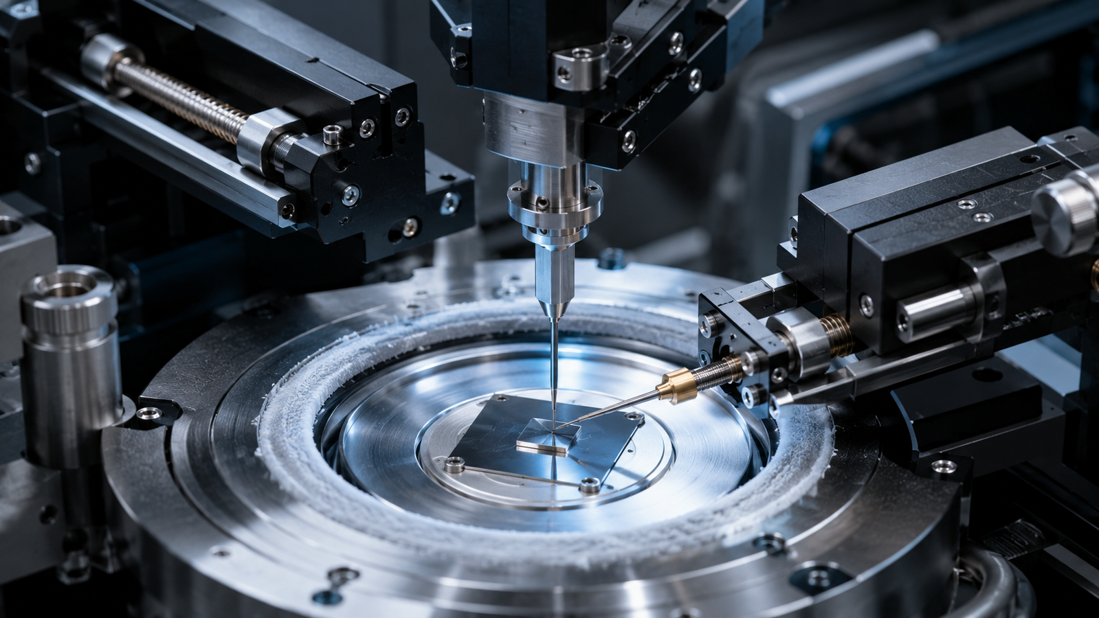
Every variable-temperature transport measurement in this knowledge hub rests on an act nobody writes up: landing a needle on a sample. Do it too gently and the contact is unstable; too firmly and the probe ploughs the film it was sent to measure; do it by hand at −150 °C and thermal contraction quietly walks the tip off its target between setpoints. Motorized probe positioning turns that act from craft into specification — micrometer-class, programmable, repeatable contact that survives a full temperature sweep. This article covers the physics of the probe–sample contact, why the landing force has a window rather than a setting, what motorization actually buys at temperature, and how to budget the errors. It builds on the electrical probe-stage overview and the four-probe & Hall geometry guide — this is the chapter about the tips themselves.
1. The Hidden Variable in Every Probe Measurement
Ask why two nominally identical four-probe measurements disagree and the suspects usually paraded are instruments and samples. The quieter culprit is the contact itself: where each tip landed, how hard it pressed, and what both did as the temperature moved. Contact behaviour is temperature-dependent physics in its own right — a junction that was ohmic warm can turn rectifying cold1 — and even a chemically stable contact changes its mechanical state as materials expand, contract and creep. Every formula in the companion geometry guide silently assumes the contact is where you think it is, as small as you think it is, and unchanged since you checked. Positioning is the discipline that makes those assumptions true.
2. Contact Mechanics 101: Why Force Sets Resistance
Two solids never touch across their whole apparent area. Real surfaces are rough, and contact happens at a sparse constellation of asperity summits whose true contact area is a small fraction of the nominal one — the picture quantified in Greenwood and Williamson’s classic model, where increasing load recruits more asperities and grows the true area roughly in proportion to force2. Electrical contact resistance lives on that constellation: current squeezes through the conducting spots, and their constriction resistance falls as load brings more and larger spots into play. Push harder and the contact resistance drops — steeply at first, then with diminishing returns as the junction approaches intimate contact; surface films and oxides add a barrier term that fresh mechanical contact can pierce, which is why a slight scrub often completes what force alone starts. The practical curve every prober learns is resistance versus landing force: a cliff, then a floor.
3. The Landing Window: Too Light, Too Hard, Just Right
The cliff-and-floor curve has edges on both sides, and they define the landing window. Too light, and the contact sits on the cliff: resistance is high, unstable, and hostage to vibration, drift and the smallest thermal motion — readings wander and reversal protocols cannot rescue a junction that changes between the measurements being averaged. Too hard, and the tip stops measuring the sample and starts editing it: soft films scratch, brittle flakes crack, thin layers punch through to the substrate — catastrophic for the two-dimensional and thin-film samples where probe stations earn their keep3. Between the edges lies the window: force high enough that resistance has reached its floor and stopped moving, low enough that the sample survives inspection afterwards. The window’s width depends on tip radius, sample hardness and film thickness — generous on bulk metal, razor-thin on a nanometer film — and the entire argument for controlled, repeatable landing is that the window must be found once and hit every time.
4. Manual vs Motorized: What Changes at Temperature
At room temperature a skilled hand on a good micrometer positioner lands probes beautifully. Temperature is what breaks the craft. Sweep a stage from −190 °C to several hundred degrees and everything in the mechanical chain — sample, holder, stage body, positioner arms — expands and contracts by its own coefficient; the tip–sample relationship drifts laterally and vertically, contact force changes without anyone touching a knob, and on small samples the tip can walk clean off its pad between setpoints. Manual correction ranges from opening the enclosure (internal holders — disturbing the thermal environment every time) to turning through-wall micrometers from outside (external holders — better, but still hand–eye repeatability at the tens-of-micrometers scale, repeatedly, for hours).
Motorized positioning changes the category of the problem. Driven axes place the tip in numbers — step sizes at the micrometer scale, coordinates that may be commanded, recorded or scripted when the controller and software support it — so thermal drift becomes something you correct rather than suffer: re-approach at each setpoint, repeat the same commanded approach displacement, then verify the contact by I–V or contact-resistance measurement before trusting it — the same commanded displacement does not guarantee the same contact force after thermal drift or sample deformation. The engineering lineage is worth naming: the precision that made scanning tunneling microscopy possible was exactly this discipline — piezoelectric and fine-mechanical positioning tamed to sub-nanometer control4 — and probe-station motorization is the same idea delivered at the micrometer scale where transport measurements live. The payoff compounds with probe count: repositioning one tip by hand is craft; repositioning multiple probes — or a custom four-contact configuration — consistently at every setpoint of a twenty-point sweep is a job for axes that do not get tired.
The probe-adjustment family at a glance:
| Probe adjustment | Closed-chamber adjustment | Programmable | Force sensing | Typical use |
|---|---|---|---|---|
| Internal manual | No / limited | No | No | Simple static measurements |
| External micrometer | Yes | No | Usually no | Manual repositioning under vacuum |
| Electronic control | Yes | Potentially | Not implied | Automated or repeated positioning |
5. Interactive: The Probe Landing Lab
The simulator below puts Section 3 under your finger. One slider sets the landing force; the curve shows the contact resistance falling off its cliff onto its floor, with the damage boundary marked on the far side. The read-outs report the contact resistance, which zone the landing sits in, and what a measurement made there would look like. A “temperature drift” button perturbs the effective force the way a real sweep does — and shows why a landing that was barely inside the window at room temperature falls out of it at the extremes, while a landing placed mid-window survives.
The lesson is placement, not just pressure: the goal is the middle of the window, where the resistance floor is flat and a drift-sized perturbation changes nothing. The model is schematic — a smooth constriction-resistance curve with an instability band at low force and a damage threshold at high force, parameters chosen for teaching rather than any specific tip–sample pair — and the drift button applies a fixed force offset in the direction that thermal contraction typically pushes. Real windows must be found experimentally for each tip radius and sample; the shape of the argument is what transfers.
6. Reproducing Probe Patterns: Geometry Meets Positioning
The geometry guide’s formulas assume patterns: equal spacing for the collinear array, perimeter placement for van der Pauw, opposed taps for Hall work. Positioning is where those assumptions are manufactured. In the collinear case the spacing s enters the bulk-resistivity formula linearly, so spacing error transfers one-for-one into the answer5 — and the century of correction-factor literature quantifies how placement relative to edges moves the result6. Motorized axes turn a pattern into coordinates: the same commanded coordinates can be revisited on the next sample or the next setpoint — with the actual re-landing error validated, not assumed — and, just as valuably, documented, because a logged coordinate set is a methods-section sentence that a manual landing never quite is. For temperature-series work the compounding is decisive: a geometry reproduced at every setpoint means the temperature dependence you extract belongs to the material, not to the drift of the layout7.
7. The Error Budget: Positioning Terms, Quantified Thinking
Three families of positioning error deserve lines in the budget. Placement: lateral error moves spacings and pattern geometry — in collinear work, directly proportional error in ρ; in van der Pauw, contact-placement error mapped in the correction literature6. Force: landing outside the window trades between the instability cliff (noisy, drifting readings that no averaging fixes) and the damage boundary (a sample quietly altered mid-campaign); force also modulates any pressure-sensitive contact barrier, an effect that itself changes with temperature1. Thermal: drift across a sweep changes both placement and force unless re-approached; and the excitation current that flows through the finished contact still carries the small-junction self-heating trap8. The temperature axis itself keeps its usual calibration and offset terms9, and the general low-level disciplines — settling after every landing, reversal averaging, re-verification at the extremes — remain the floor everything stands on10.
8. A Landing Protocol: From Approach to Verified Contact
1. Approach under control. Coarse to standoff, then fine approach in defined steps; watch resistance (or the camera) for first touch rather than trusting feel.
2. Find the window once. On a sacrificial region, step force upward and record R versus landing depth: identify the floor and the damage onset; choose the mid-window setpoint.
3. Land, settle, verify. Commanded approach displacement to the setpoint; settle; contact I–V check for ohmic, stable behaviour before any data — the displacement command is repeated, the contact quality is verified, never assumed7.
4. Log the coordinates. Positions and overtravel recorded per landing — the reproducibility contract.
5. Re-approach at temperature. At each setpoint of a sweep, re-verify contact; re-land at logged coordinates if drift moved anything; verify again at both extremes.
6. Inspect afterwards. Post-campaign imaging of the landing sites; scratches or punch-through invalidate more than the last point — they date every measurement since the damage began.
9. Hardware Notes: Running This on a Stage
The catalogued platform for this article is the InSitu Pro™ AECH400V-EC precision electronic adjustable probe stage: two electronically controlled probe holders with tungsten-carbide gold-plated probes and BNC × 2, XYZ travel of ±6 mm per axis, on a vacuum-capable −190 °C to 400 °C platform at ±0.1 °C — with a specified displacement accuracy of 5 nm for the motion system. Two important boundaries follow. First, the standard configuration supports two-terminal measurements directly, or serves as the movable-probe portion of a broader contact layout; a complete four-terminal or van der Pauw pattern requires additional fixed contacts or a custom multi-probe configuration confirmed at quotation. Second, the 5 nm figure is a displacement-accuracy specification — it does not by itself define positioning repeatability, minimum step size, backlash, absolute coordinate accuracy, or any probe-force control or force resolution; confirm those parameters separately for the intended configuration. The same probe-holder family is also catalogued in internally adjustable and externally adjustable (through-wall micrometer) versions. Manual-positioner platforms such as the AECH600S / AECH400SV remain excellent where patterns are static and sweeps are short; the motorized case earns its cost as temperature span, re-landing count and sample value climb. For the full family, see the electrical stage line or match your experiment with the stage selector.
- Precision Electronic Adjustable Probe Stage (AECH400V-EC) — two electronically controlled probes with heating, cooling and vacuum: the catalogued motorized configuration; multi-probe layouts by quotation.
- Electrical Heating & Cooling Stage (AECH600S / AECH400SV) — the manual-positioner four-probe workhorse for static patterns.
- Four-probe & Hall measurements at variable temperature — the geometries these positioners are asked to reproduce.
- All InSitu Pro™ electrical stages — the complete line, or use the interactive stage selector.
10. FAQ: Motorized Probe Positioning
11. Keep Exploring the InSitu Pro™ Knowledge Hub
This article completes the probe-side story of the electrical cluster. To keep going:
- In-situ heating, cooling & electrical stages: a theory guide — the pillar article on how temperature-controlled stages work.
- In-situ electrical probe stages — hardware anatomy, contact physics and measurement pitfalls.
- Four-probe & Hall measurements at variable temperature — the geometries and field protocols these probes serve.
- Resistance vs temperature: measuring R(T) in-situ — what the verified contacts are for: the fitting methodology.
- How to choose an in-situ heating & cooling stage — the five-step selection guide.
References
This article discusses probe positioning and contact methodology in general terms. Contact-resistance behaviour, landing-force windows, damage thresholds and drift magnitudes are idealized and depend on tip material and radius, sample hardness and thickness, surface condition, atmosphere and instrumentation; real values must be established experimentally for each tip–sample combination and validated against the manufacturer’s datasheets before quantitative use. The interactive simulator is a schematic teaching tool built on a stated illustrative model, not measured data for any real system. Motorized-positioning specifications — resolution, travel, probe count, force control — are configuration-specific; contact ACS Material to discuss options for your application.