Overhead stirrer impeller types differ in how they move liquid, so impeller choice is a major part of the mixing setup. Propellers, turbines, paddles and anchors differ in their flow patterns and power demand. This guide explains axial and radial flow, why viscosity changes which impeller works, and what the power number tells you about the turning effort an impeller needs. It ends with the stirring tools listed on the ALab™ OS-Pro and OS-S series, described only in ACS Material's own words. For how stirring compares with other ways of mixing, see our guide to laboratory mixing methods.
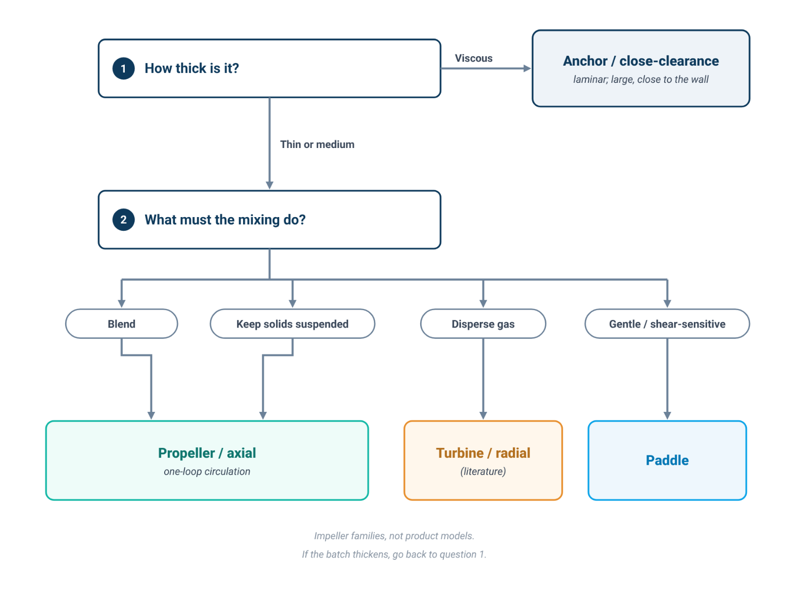
Quick answer: In thin to medium liquids, axial-flow impellers such as propellers circulate the vessel and help keep solids suspended; radial-flow impellers such as flat-blade and Rushton turbines direct flow toward the wall and are used where more local shear is wanted, for example in dispersion [1][2]. Two-blade paddles are a traditional reference geometry in mixing correlations [4]. As viscosity rises and Reynolds number falls, mixing can move into the laminar regime, where large impellers such as anchors, screws and ribbons are commonly used [2][3]. The power number is a dimensionless measure of impeller power demand; its value depends on impeller and vessel geometry, so tabulated literature values are guides rather than direct predictions for a lab beaker [1][4][5]. ACS Material lists propeller, paddle and anchor stirrers among 12 ALab™ tool names; no turbine is listed.
1. Axial vs Radial Flow, and Why Viscosity Changes the Choice
The first split is by flow regime. A University of Michigan chemical-engineering module puts it simply: "Impellers are classified as either laminar (viscous) or turbulent mixers" [2]. Turbulent-regime impellers are then split by the direction in which they push liquid.
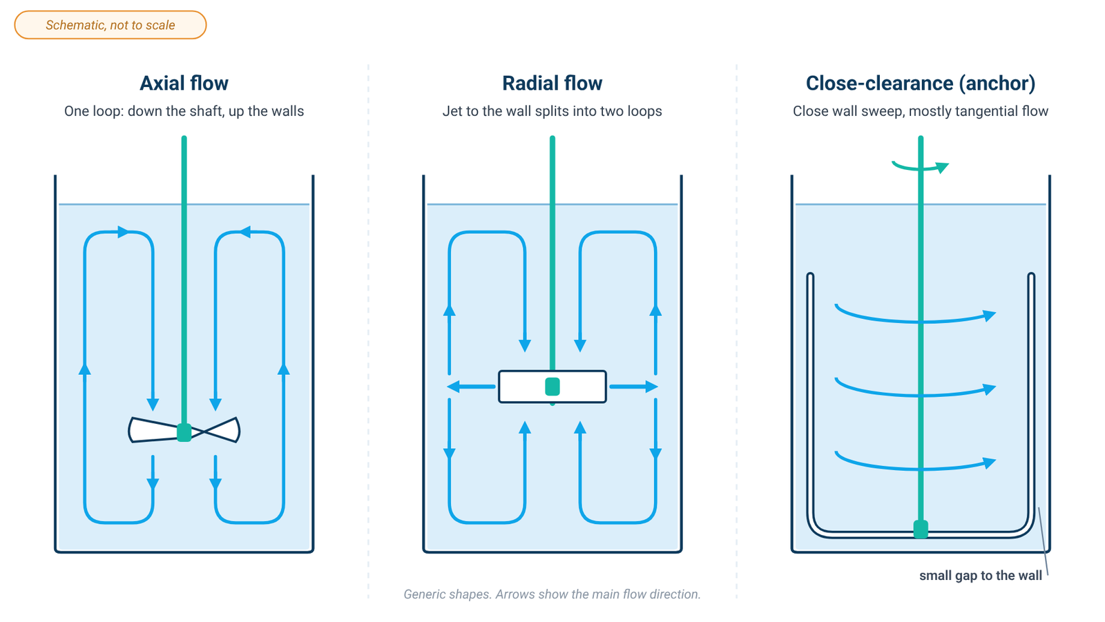
Axial flow. Axial-flow impellers "cause the tank fluid to flow parallel to the impeller's axis of rotation" [2]. With the shaft vertical, the impeller pumps liquid down towards the base; it turns at the bottom, rises along the wall and returns to the impeller, forming one large loop. The same module notes that axial-flow impellers "are very useful in mixing solid-liquid suspensions because they prevent the solid particles from settling at the bottom of the tank" [2]. Propellers are the classic example. In industrial mixers, profiled hydrofoils were developed to give a similar velocity profile and are "generally considered to be 'low-shear'" [1].
Radial flow. Radial-flow impellers push liquid "perpendicular to the impeller's axis of rotation" [2], in a jet aimed at the vessel wall. The jet splits at the wall into one loop above the impeller and one below. Flat-blade turbines are the common examples, and the Michigan module recommends radial-flow impellers "in situations where high shear rates are needed, such as in dispersion processes" [2]. A 2017 review of impeller performance classes pitched-blade turbines as mixed flow, with both axial and radial components [1].
Viscosity and the Reynolds number. Flow regime is described by the impeller Reynolds number, Re = ρND²/µ, where ρ is liquid density, N rotational speed, D impeller diameter and µ viscosity [3]. Increasing viscosity lowers Re when the other terms are unchanged. In viscous laminar mixing, the impeller is commonly large relative to the vessel: for "very viscous fluids where laminar mixing is present, the diameter of the impeller approaches the diameter of the tank" [2]. Ribbon, screw and anchor impellers are classic laminar shapes [2].
Vortex and baffles. A lab beaker usually has no baffles. Stirred fast, its contents swirl as a whole and form a central vortex. Dickey warns that a strong central vortex "usually means that the entire tank contents are moving in solid-body rotation", with almost no mixing across or up and down the vessel, and that a deep vortex draws air into the liquid [3]. Industrial vessels use baffles, vertical plates near the wall that redirect the rotating flow into vertical flow; Dickey calls them "necessary for nearly all turbulent mixing applications" [3].
2. The Main Overhead Stirrer Impeller Types
This section describes impeller families as the mixing literature describes them. It is not a list of ALab™ products; Section 4 covers the ALab™ tool list.
Propeller. The propeller is the classic axial-flow impeller [2]. A study of power consumption in mixing vessels notes that propeller-type impellers "are used for low-viscosity liquid and solid-liquid suspensions", in vessels from portable mixers to large tanks [4].
Paddle. The two-blade paddle is a traditional reference geometry for mixing-power correlations [4]. Furukawa et al. also reproduced the laminar power number of an anchor "by considering the anchor as a wide paddle impeller" [4].
Turbine. In the literature, pitched-blade turbines are mixed-flow impellers, flat-blade turbines are radial, and Rushton disc turbines are radial impellers used for gas dispersion; Grenville et al. describe the Rushton turbine as "high-shear" [1]. No ALab™ turbine is listed, so turbine terminology in this article is literature-only.
Anchor. An anchor is a laminar, close-clearance impeller: its arms follow the vessel wall with a small gap. Close-clearance impellers keep the liquid next to the wall moving and are "very useful in heat transfer applications" for that reason [2]. Their weakness is vertical mixing. Dickey notes that "the vertical arms of the anchor impeller create almost no vertical movement in the bulk material" [3]. Industrial designs add angled blades to an anchor, or use a helical ribbon, which Dickey calls the most effective design for blending high-viscosity fluids [3].
3. Power Number: What It Tells You, and What It Doesn't
Definition. The power an impeller draws is written as P = Po·ρ·N³·D⁵, where Po is the power number [1]. Rearranged, Po = P/(ρN³D⁵). The power number is a dimensionless drag coefficient for an impeller shape [1]. In turbulent flow, P scales as N³D⁵, so the same percentage increase in impeller diameter changes predicted power more than the same percentage increase in speed, all else equal [1].
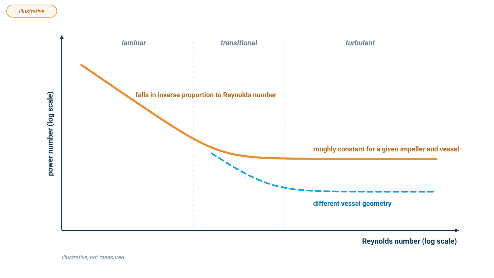
How it behaves. In turbulent flow, the power number of a given impeller in a given vessel is roughly constant, so the review can tabulate one typical value per shape [1]. In laminar flow it is not constant: it falls in inverse proportion to the Reynolds number, and the constant linking the two is "specific to the impeller design and tank geometry" [6]. In the laminar range, impeller power and pumping scale with the cube of impeller diameter [3], which helps explain why viscous laminar mixing commonly uses impellers large relative to the vessel [2][3].
Typical literature values. The table below gives typical turbulent-regime power numbers from Table 1 of the 2017 impeller-performance review [1]. The names are the review's own.
Literature-only values for the turbulent regime reported by Grenville et al. [1]; not measured for any ALab™ tool. Power number depends on vessel geometry, and baffling can change it substantially, so do not use these values as direct predictions for an unbaffled lab beaker [4][5]. Power-number values are from Table 1; flow classes are from the review's text and Fig. 1.
| Impeller (literature name) [1] | Flow class [1] | Typical power number [1] |
|---|---|---|
| Narrow-blade hydrofoil | Axial | 0.30 |
| Wide-blade hydrofoil | Axial | 0.70 |
| Pitched-blade turbine | Mixed | 1.50 |
| Flat-blade turbine | Radial | 3.00 |
| Rushton turbine | Radial | 5.00 |
| HSD-Sawtooth (high-shear disperser) | Dispersion | 0.10 |
Why the vessel matters. Baffling can change power number substantially. In one study, the same 90° pitched-blade turbine had a mean power number of 4.45 with four standard baffles and 0.88 with no baffles [5]. Furukawa et al. likewise use separate correlations for unbaffled, standard-baffled and fully baffled vessels [4]. Use literature values to compare literature cases, not to predict the load in your beaker.
From power to torque. Shaft power is also P = 2πNΓ, where Γ is torque [6]. At fixed speed and fluid density, where the power-number relation applies, a higher power number or larger impeller diameter means higher predicted shaft power and therefore higher torque demand [1][6]. Motor torque availability also depends on speed; at constant power, torque falls as speed rises [7]. Our overhead stirrer vs magnetic stirrer guide explains how model torque, viscosity and water-volume ratings should be read separately.
4. ALab™ Stirring Tools: What the ALab™ Accessory List Includes
The OS-Pro series LCD digital overhead stirrer and OS-S series LED digital overhead stirrer share the same list of optional stirring tools. The table gives each tool's name, material and recommended use as ACS Material specifies them; where a tool is listed in two materials, both are shown.
| Stirring tool | Material | Recommended use |
|---|---|---|
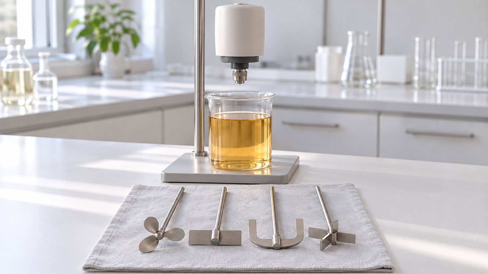
| Propeller stirrer | 316L stainless steel / PTFE coated | Standard stirring at medium and high speeds |
| Straight stirrer | 316L stainless steel / PTFE coated | Low viscosity media at medium and high speeds |
| Paddle stirrer | 316L stainless steel / PTFE coated | Gentle mixing at low and medium speeds |
| Centrifugal stirrer | 316L stainless steel / PTFE coated | Blades open while speeding; narrow neck vessels, medium to high speed |
| Grand propeller stirrer | 316L stainless steel | Standard stirring |
| Grand paddle stirrer | 316L stainless steel | Gentle mixing of samples that stratify easily or are sensitive to shear |
| Grand anchor stirrer | 316L stainless steel | Standard stirring, or samples that precipitate easily |
| Grand dissolving stirrer | 316L stainless steel | Breaking down granules in the mixture with strong shear |
| Flat-blade stirrer | 316L stainless steel | Medium speed stirring; low and medium viscosity materials |
| Anchor stirrer | 316L stainless steel | Low speed stirring; medium and high viscosity materials |
| Radial-flow stirrer | 316L stainless steel | Medium or high speed agitation; low or medium viscosity; gas in liquid |
| Spiral stirrer | 316L stainless steel | Medium or high speed agitation; medium and high viscosity; homogenization or suspension |
Listed as optional accessories for the OS-Pro and OS-S series (identical lists). Names, materials and uses follow ACS Material's descriptions; no flow pattern, power number or model pairing is specified for any tool.
All listed stirring tools have a shaft diameter of Ø8 mm. The OS-Pro additionally has a chuck clamp range of Ø0.5–10 mm.
The OS-T Plus series overhead stirrer has a paddle "through-the-top" design for easy container replacement, but no stirring-tool set is listed.
5. Matching the ALab™ Tools to the Impeller Families
ACS Material describes each tool by its recommended use only. They give no blade angle, flow direction, power number or pairing with a particular stirrer model. So the safe way to read them is in two groups.
Same name as a literature family. In this article, only the ALab™ names propeller, paddle and anchor are matched by name to the same-named literature families. Even for those three, the Recommended use text in the table in Section 4 remains the product evidence; blade geometry, wall clearance, power number and a pairing with any particular stirrer model are not specified.
Recommended use only. For the Straight, Centrifugal, Grand dissolving, Flat-blade, Radial-flow and Spiral stirrers, use only the Recommended use text in the table in Section 4. Do not infer a literature impeller geometry, power number or additional process capability from the product name.
6. Set-up Checklist
- Viscosity now and at the end: increasing viscosity lowers Reynolds number when the other terms are unchanged and can move the batch toward laminar flow [3]; reassess impeller choice if the material thickens.
- Job: blending, keeping solids suspended, dispersing gas or gentle mixing of a shear-sensitive sample each point to a different family (Sections 1–2).
- Vessel neck: check that the impeller fits through the opening; for narrow necks ACS Material lists the centrifugal stirrer.
- Vortex: in an unbaffled beaker, avoid a deep central vortex that draws air into the liquid [3].
- Material: some tools are listed in 316L stainless steel and in PTFE coated versions; check compatibility with your chemistry.
7. Frequently Asked Questions
Propeller vs turbine impeller: which should I use?
In the literature, a propeller gives axial flow for blending and solids suspension in thin to medium liquids, and a flat-blade or disc turbine gives radial flow and more local shear, for example for gas dispersion [1][2]. ACS Material lists ALab™ propeller stirrers but no turbine.
Which impeller families are used for viscous liquids?
In laminar mixing, large impellers such as anchors, screws and ribbons are commonly used [2][3]. The ALab™ anchor stirrer is listed for "Low speed stirring; medium and high viscosity materials".
Can I use literature power numbers for my beaker?
Only as a rough guide for comparing impeller shapes. In one study, the same impeller had a mean power number of 4.45 with four standard baffles and 0.88 with no baffles [5]. No power number is specified for any ALab™ tool.
8. Keep Exploring the Mixing Hub
- Laboratory mixing methods guide: stirring, homogenizing, vortexing, shaking and rolling compared by volume, viscosity and shear.
- Overhead stirrer vs magnetic stirrer: viscosity, torque and volume ratings for nine ALab™ overhead models.