
Many avoidable submission, geometry, and scale failures are decided before any machine turns on — in the file. A model that is not watertight, exported in the wrong units, or tessellated too coarsely will fail, mis-scale, or print visibly faceted on any process, from desktop FDM to industrial metal and ceramic systems.1,2 This guide walks the file-preparation chain that professional workflows share: what an STL actually is, when to send STEP or 3MF instead, the unit and resolution traps, route-specific preparation for resin, powder-bed, metal, and ceramic printing, and a handoff checklist that saves a revision cycle with any provider.2,3
What an STL actually is — and when to send something else
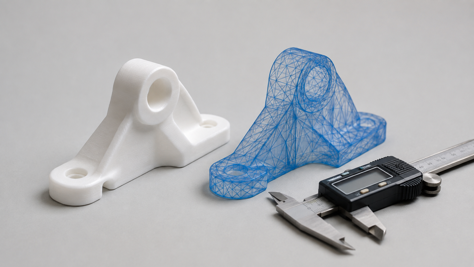
An STL file describes only one thing: the surface of your part, approximated as a mesh of triangles. No units, no colors, no materials, no tolerances, no feature history — just triangles and their facing directions.2 That radical simplicity is why STL remains supported across nearly every slicer and service-bureau workflow, and also why so much can go wrong: the format cannot tell anyone how big the part is meant to be or which surfaces matter.2,3
Two alternatives fix specific weaknesses. STEP (.stp) carries the exact CAD geometry — true curves, not triangles — plus units, and is the right companion file whenever a provider may need to check wall thicknesses, adjust features, or machine surfaces after printing.2 3MF is a modern mesh container that embeds units, orientation, and material metadata, closing STL’s most common failure modes; the specification is openly published as the 3MF Core Specification and standardized as ISO/IEC 25422, though toolchain support still varies, so confirm before relying on it.4 A practical professional default: model in CAD, export both STEP and STL, and let the STL drive slicing while the STEP answers questions.
The units trap
Because STL stores no units, the number “25.4” in a file is just a number — one toolchain reads it as millimeters, another as inches, and the part arrives 25.4× too large or too small.2 The industry convention is millimeters, and the defense is procedural: set the CAD export dialog to mm explicitly, then open the exported file in a viewer or slicer and check one known dimension before sending it anywhere. Providers routinely catch scale errors by asking for one overall dimension in the request — write it in every RFQ and the trap disarms itself.
Watertight geometry and consistent normals
Slicers need a mesh that unambiguously separates inside from outside. Two integrity properties deliver that. Watertight (manifold) means the surface is fully closed — no holes, no gaps, no edges shared by more or fewer than two triangles; a mesh with pinholes or self-intersections has no defined interior, and slicing becomes guesswork.2 Consistent normals means every triangle’s facing direction points outward; flipped patches read as inside-out geometry and slice as voids.2
Both defects come overwhelmingly from the modeling side: surfaces stitched from imported geometry, boolean operations that left slivers, duplicate shells sitting on top of each other. Most CAD packages and free mesh tools can detect and auto-repair the routine cases; the discipline is simply to run the check before export rather than let the printer discover the problem.2,3
Mesh resolution: fine enough, not finer
Export settings decide how closely the triangles hug your true curves — usually as a chord (deviation) tolerance and an angle limit. Set them too coarse and cylinders print visibly faceted; set them absurdly fine and the file balloons with zero print benefit, because no process can reproduce facets smaller than its own resolution.2,3 The working rule: make the tessellation error comfortably smaller than both your smallest meaningful feature and the process resolution, then stop. A mesh is over-resolved when additional facets stop preserving meaningful geometry relative to the process resolution, the inspection need, and the provider’s upload limits — past that point, extra fineness only slows every downstream step.
Resolution interacts with precision downstream: tessellation error adds to — never subtracts from — the process’s own accuracy budget, which is why file preparation is the first line item in any tolerance discussion. Our precision and tolerance guide covers the rest of that budget.1
Interactive: file-prep triage
Pick the symptom; get the diagnosis and the fix. The five cases below account for most rejected uploads.
Route-specific preparation
Beyond universal integrity, each process family adds its own file-level considerations.3 Resin (SLA/DLP): enclosed volumes trap liquid resin, so hollow parts need drain holes designed in, and delicate free-standing features should be flagged so supports can be placed where scars are acceptable.5 Polymer powder bed (SLS/MJF): parts print without separately printed supports, so the file question shifts to nesting and escape holes for internal powder — enclosed voids must let unfused powder out.3 Metal: geometry is inseparable from support strategy and thermal behavior, so metal providers usually want the STEP file and the freedom to orient and support — the design conversation in our metal 3D printing guide starts at the file.6 Ceramic: binder-based, sintering-densified routes print the part oversize by calibrated shrinkage factors; that pre-compensation is applied by the provider’s workflow, not in your CAD; unless a provider explicitly asks for pre-compensated geometry, send nominal fired dimensions and say so explicitly, as explained in our guide to how ceramic 3D printing works.7,8
The common-errors checklist
Before any upload, sweep the file against the failure modes that dominate rejected jobs: non-manifold edges and holes; flipped or mixed normals; wrong units; duplicate or nested shells occupying the same space; over- or under-tessellation; tiny unintended gaps between bodies that were meant to be one part; and features thinner than the process can form — the printability side of that last item is process-specific and covered across our 3D printing overview.2,3,9 Many items take seconds to screen — complex mesh defects may need repair or an engineering look — and all of them take a revision cycle to discover late.
Handing off to a provider
A complete handoff package answers the questions before they are asked: the STL (or 3MF) plus the STEP original; explicit units and one overall reference dimension; material and quantity; critical dimensions and tolerance callouts — only where function needs them; surface-finish expectations; and any orientation or cosmetic-face preferences.9 Standardized test artefacts exist precisely to characterize what a given machine and workflow can hold, so for tolerance-critical work, ask the provider what their system demonstrates rather than assuming datasheet figures — artefact results describe system capability, not an acceptance guarantee for your part.10,11 For metal work, our metal 3D printing service reviews uploaded files against exactly this checklist before quoting.
FAQs
1. What file format do I need for 3D printing?
STL is the universal baseline; 3MF adds units and metadata where supported; STEP preserves exact CAD geometry and is the best companion file for engineering work. A professional default is to send STL plus STEP together.2,3
2. Why is my 3D print the wrong size?
If the mismatch is exactly 25.4× or 1/25.4×, the cause is almost certainly an inch–millimeter unit mismatch — STL carries no units, so state them in the filename and confirm at upload. Smaller deviations point elsewhere: process shrinkage, calibration, compensation, orientation, material behavior, or the tolerance model in play.
3. What does watertight (manifold) mean?
The mesh is a fully closed surface with a defined inside and outside — no holes, gaps, or edges shared by anything other than exactly two triangles. Slicers require it to compute where material goes.2
4. What STL resolution should I export?
Fine enough that facet error is below your smallest meaningful feature and below the process resolution — and no finer. Over-resolved exports bloat files without improving the print.2,3
5. Do I scale my ceramic part for shrinkage myself?
Unless the provider explicitly requests pre-compensated geometry, send nominal fired dimensions and flag the critical features — on binder-based, sintering-densified routes the qualified provider applies calibrated, direction-specific scaling in their workflow. Double compensation is a classic error.7,8
References
This article is provided by ACS Material LLC for educational purposes and describes general file-preparation practice for additive manufacturing. Format capabilities, repair behavior, and acceptable file sizes vary by software and provider; process-specific limits (minimum features, drainage, supports, shrinkage compensation) are workflow-dependent and should be confirmed with your provider. The interactive triage tool is a qualitative teaching aid, not file-repair software.