
Every 3D printed part is built layer by layer — but supports solve a different physical problem in each process family, and every choice of which way is “up” decides where layer lines fall, where support scars land, and how the part behaves in which direction.1,2 This guide explains why supports exist, how the answer changes across FDM, resin, powder-bed, metal, and ceramic printing, and how to orient parts so the geometry works with the process instead of against it.
Why supports exist at all
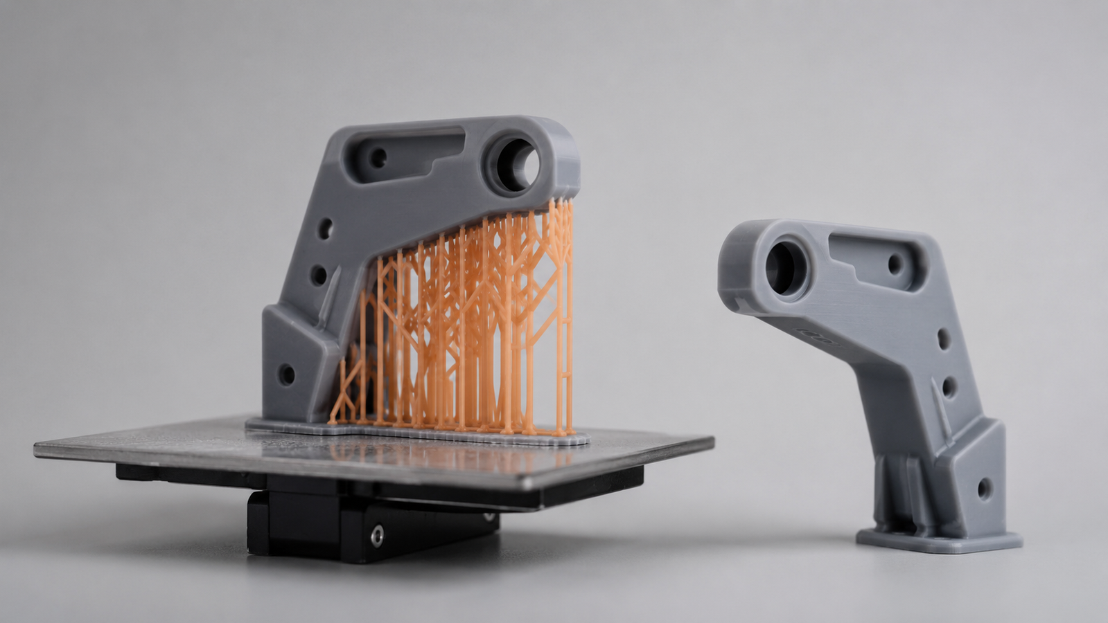
Supports do different jobs in different families. In material extrusion, they carry regions that cannot yet bridge or overhang reliably — fresh material over empty space sags until it has footing.1,2 In vat photopolymerization, thin supports help the part survive the separation forces of each peel cycle and hold delicate cured features in position — the load is the process pulling on the part, not simply the part sagging.3 In metal powder bed fusion, supports anchor the part against residual-stress distortion and conduct heat down into the build plate.4,5 And in ceramic workflows, supports can protect fragile green geometry during printing and handling. One word, four different physics.
Across these roles, supports add build time, material use, and removal labor — and they ultimately have to come off: a step budgeted in our post-processing guide — and every removal point leaves a witness mark that needs surface finishing if the face matters. That is why support strategy is inseparable from orientation strategy — the goal is not just fewer supports, but supports in places you do not care about.2,6
FDM and resin: the classic support story
In material extrusion, each layer needs the previous one under enough of its footprint; the steeper the overhang, the less it has, until sagging and curling begin. Slicers generate breakaway lattices or dissolvable secondary materials under the failing regions, and bridging lets short horizontal spans print unsupported where anchored on both ends.1,2 In vat photopolymerization, thin resin supports hold delicate cured features against the peel forces of the process and position the part for drainage; their contact points are small but numerous, and their scars sit exactly where the supports touched — which is why cosmetic faces are oriented away from them.3 A fuller comparison of the polymer processes lives in our FDM vs SLA vs SLS guide.
Polymer powder beds: no separately printed supports
Polymer powder-bed fusion (SLS, MJF) normally prints without separately printed supports: the surrounding unfused powder usually replaces printed scaffolds for overhangs and islands, which is why these processes handle interlocking assemblies, dense nesting, and complex organic geometry so freely.7,1 The cost shows up elsewhere — thermal history across the build cake governs accuracy, geometry remains constrained by powder escape, recoater interaction, and nesting, and enclosed voids must include escape holes so unfused powder can leave. Freedom from supports is not freedom from process physics.7
Metal: supports as heat anchors
Metal laser powder bed fusion needs supports for both jobs at once. Downward-facing surfaces melt into loose powder and form rough dross; unanchored regions warp as residual stress accumulates; and heat concentrated in tall thin features needs a conduction path out.4,5,6 Metal supports are therefore engineered structures — placed, angled, and perforated deliberately — and their removal is a machining or hand-finishing operation budgeted into the part cost. Orientation decisions here often carry exceptional weight, which is why metal design reviews start with them; our metal 3D printing guide walks the full design conversation.4
Ceramic green parts: supporting chalk
Slurry-based ceramic vat photopolymerization adds a fragility twist: the printed green part is a binder-ceramic composite with chalk-like strength, so unsupported spans and delicate free ends need support during printing and gentle handling afterward, with vat-style supports placed where removal scars are acceptable on the fired part.8,9 Powder-bed ceramic routes, like their polymer cousins, lean on the surrounding powder instead. The full print–debind–sinter chain is explained in our guide to how ceramic 3D printing works.
Interactive: overhang & orientation explorer
Pick an overhang angle and a process family to see whether the feature typically needs support — and why the answer differs by family.
Choosing an orientation: the three-way negotiation
Orientation optimizes three things that rarely agree.2,10 Support economy: rotate the part so steep overhangs become self-supporting slopes and support volume — and its removal labor — shrinks. Critical surfaces: put cosmetic and functional faces up-skin or vertical, away from support contact and down-skin roughness. Directionality: layer-wise builds behave differently along the build axis than across it, so load paths and tight-tolerance features should respect the build direction — the precision side of that story is covered in our precision and tolerance guide. Overhang thresholds commonly cited around 45° from the horizontal build plane are illustrative starting points, not laws; the real limit moves with machine, material, parameters, and feature size, and capability is demonstrated on standardized test artefacts rather than assumed.11 (Process-family terms follow the ISO/ASTM 52900 vocabulary.)12 When two goals conflict, the tiebreaker is almost always which surfaces the function actually touches.
For flexible parts, orientation carries one more consideration — soft features can deform under their own supports, a wrinkle covered in our flexible materials guide; for elastomer production work, our elastomer 3D printing service handles support and orientation strategy as part of the quote.3
FAQs
1. What angle needs support in 3D printing?
A commonly cited illustrative starting point sits around 45° measured from the horizontal build plane for extrusion and metal processes, but the true threshold is machine-, material-, and parameter-dependent — treat it as a test point, not a law.6
2. Which 3D printing process needs no supports?
Polymer powder-bed fusion (SLS, MJF) normally prints without separately printed supports because unfused powder carries the geometry; enclosed voids still need powder-escape holes.7
3. Why do metal prints need so many supports?
Metal supports do double duty: they hold overhangs and anchor the part against residual-stress warping while conducting heat into the plate. They are engineered structures whose removal is budgeted into the job.4,5
4. Do support marks affect surface quality?
Yes — every contact point leaves a witness mark. Orientation strategy places supports on non-critical faces, and critical surfaces are finished after removal where required.2,6
5. How should I orient a part for strength?
Use measured directional-property data for your material, machine, parameters, and post-processing route — layer-wise processes behave differently along the build axis than across it, and the qualified data, not an assumed universal stronger axis, should set how critical load paths are oriented. Verify on test coupons for critical work.1,12
References
This article is provided by ACS Material LLC for educational purposes and describes general support and orientation practice in additive manufacturing. Overhang thresholds, support styles, removal methods, and directional behavior vary substantially with process, machine, material, parameters, and geometry; figures cited are representative starting points from the referenced literature, not guarantees. Confirm capability for a specific part with your provider, using standardized test artefacts and project coupons where tolerances or loads are critical. The interactive explorer is a qualitative teaching aid.