
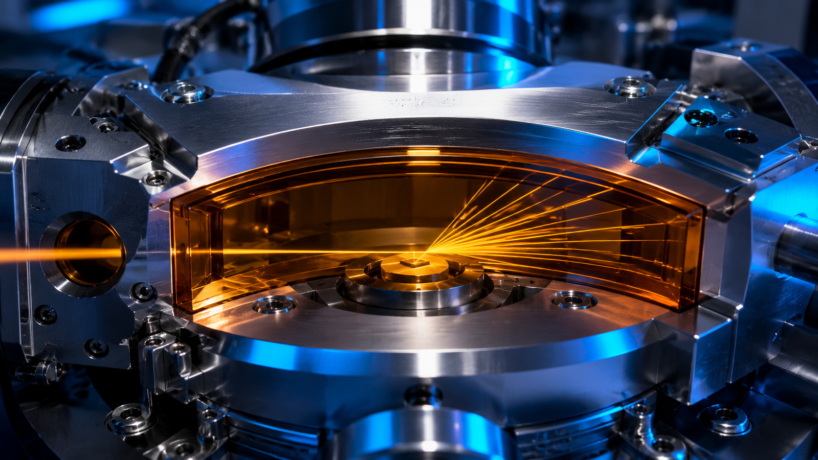
Nearly every non-ambient diffraction pattern — heated, cooled, pumped, or cycling — reached the detector through a window or a cell wall. The furnace needs a sealed atmosphere; the cryostat needs vacuum; the X-rays need to get in, diffract, and get out — and the thin film that reconciles those demands is one of the least discussed, most consequential components on the instrument. Get it right and the window becomes a quiet, characterized part of the background rather than the dominant feature. Get it wrong and it donates a broad amorphous hump to your background, eats your low-angle intensity, or — subtler and worse — lets a heated stage quietly shift every peak you measure. This guide is a close look at that thin film and the geometry around it: what the 2θ opening of a stage actually means, why Kapton earned its place as the default, what the alternatives buy you, and how heat turns window geometry into a peak-position problem you can predict and correct.
1. Why Sealed In-Situ XRD Stages Need a Window
An in-situ experiment is a negotiation between two incompatible requirements. The sample demands an environment — a defined temperature, a controlled gas, a vacuum, sometimes an electrochemical cell running a real charge cycle — and real-time diffraction is only as good as that environment is stable1. The X-rays demand a clear path: in, through the sample, and out across the full angular fan of the diffraction cone. The window is where those two demands meet. Purpose-built sample cells put the problem front and centre, engineering thin transmissive walls that hold flowing gas and elevated temperature while scattering data stream through them2; environmental chambers for polymer and soft-matter work do the same for humidity and solvent atmospheres3; and modern laboratory operando instruments run entire battery cycles behind X-ray-transparent walls between synchrotron campaigns4. In every one of these, the film over the aperture is a full member of the optical system — every in-situ pattern is a duet: your sample, plus the window it lives behind.
2. XRD Stage Window Geometry: Understanding the 2θ Opening
Reflection-mode powder diffraction is built on parafocusing: source, sample surface, and detector ride a common focusing circle, a geometry worked out in the earliest goniometer designs and still the backbone of the Bragg–Brentano instrument5. A stage bolted onto that geometry must respect it. As the goniometer scans, the incident beam arrives at angle θ and the diffracted beam leaves at θ on the other side — so a small circular port is rarely enough. Stages answer with a continuous arc — or a dome, or a set of positioned apertures — most commonly a transparent band wrapped around the sample that keeps both beams unobstructed across the scan you intend to run. That is why stage specifications quote the window as a 2θ span: a frame opening of 0°–164° means the window itself permits a very broad range — the usable 2θ span still depends on the incident optics, beam footprint, sample holder, and detector travel — while a narrower opening quietly amputates the high-angle reflections that lattice-parameter work depends on. Dome-style stages take the idea to its limit, stretching a hemispherical window over the sample so the diffraction vector can be tilted and rotated through the whole orientation space for texture and stress work at temperature6.
3. Kapton XRD Windows: Benefits, Background & Limits
Ask why the film is nearly always amber, and the answer is a polymer that behaves unreasonably well in every direction at once. Kapton is a wholly aromatic polyimide — poly(4,4′-oxydiphenylene pyromellitimide) — a rigid, imide-linked backbone identified and characterized in classic surface-analysis work7. For a window, that chemistry translates into an unusual bundle of virtues: the film is made of light elements only, so it absorbs little; it is tough and creep-resistant as a thin membrane; it resists a wide range of solvents and reactive gases; and it survives temperatures that would destroy ordinary polymers. Whether a given film holds a given window, though, is an engineering question — grade, thickness, unsupported span, pretension, pressure difference, temperature, and exposure time all enter — and should be confirmed for the actual stage configuration. It can even be optically flat in the sense X-rays care about: in one beamline characterization, polyimide film measured flatter than the beryllium foils tested alongside it — a reminder that thickness nonuniformity distorts a coherent wavefront, and that window optical quality is measured, not assumed8.
Kapton's one honest tax is scattering. An amorphous polymer has no sharp reflections, but it does have structure, and a Kapton window contributes a broad, low-lying hump to the background along with enhanced scatter at low angles — exactly where weak superlattice peaks or small-angle features may live. The discipline is the same one every cell designer practises: characterize the empty stage under the same optics and scan program — and at representative temperature and atmosphere, since the background can drift with both — then treat those patterns as part of the instrument2. A window background that is characterized can be subtracted when conditions match closely — and folded into the refinement model when they cannot.
4. The Rest of the Window Family
When Kapton's limits bind — temperature above its comfort zone, chemistry that attacks polyimide, or a hunger for every last photon — the alternatives each trade something for something. Beryllium is the classic high-transmission choice, nearly transparent to hard X-rays and stiff enough to span large openings, but it is toxic to machine, oxidizes, and its polycrystalline grain can add texture and roughness of its own8. Glassy carbon offers rigidity, chemical inertness, and clean scattering, which is why standardized operando battery cells clamp their electrode stacks between rigid glassy-carbon windows9. Graphite and aluminium serve as workmanlike foils where modest transparency suffices; diamond, grown as thin CVD membranes, buys extreme thermal and mechanical performance at extreme cost; and single-crystal windows such as sapphire domes are superbly strong and clean of powder rings, at the price of the occasional intense single-crystal spot wandering through a scan. Scaling any of these to large areas is an engineering discipline of its own — dedicated development work exists purely on fabricating big, uniform, high-transmission X-ray windows10. And at sufficiently high photon energy the calculus changes again: hard X-rays pass through millimetres of steel, which is how transmission cells with metal bodies run routine operando work at high-energy sources11. Whatever the material, the accounting is the same table lookup: attenuation is set by the mass attenuation coefficient of the film at your photon energy, tabulated for every element and many compounds in the standard reference data12.
| Window material | Main advantage | Background / diffraction note | Mechanical / thermal note | Main caution |
|---|---|---|---|---|
| Kapton / polyimide | Low-Z, flexible, widely available | Broad amorphous background | Thickness and span set pressure capability | Film temperature and chemistry per grade |
| Beryllium | High transmission at hard-X-ray energies | Possible nonuniformity, crystalline features | Rigid and strong | Toxic if machined or damaged |
| Glassy carbon | Chemically inert, rigid | Smooth amorphous contribution | Suits rigid cell windows | Thicker than polymer films |
| Graphite | High-temperature capability | Carbon scattering background | Brittle depending on form | Transmission depends strongly on thickness |
| Aluminium | Easy fabrication | More absorbing than low-Z polymers | Mechanically convenient | Energy-dependent transmission |
| Diamond / sapphire | Extreme strength and thermal resistance | Single-crystal spots may appear | Expensive, specialized | Orientation and cost |
Qualitative comparison only; transmission and mechanical suitability depend on photon energy, grade, thickness, unsupported span, pressure difference, and geometry.
5. X-Ray Window Transmission: Thickness, Energy & Angle
The physics of a window is one line: transmitted intensity falls exponentially with the path it crosses, I = I0 exp(−μteff), where the linear attenuation coefficient μ is the density times the tabulated mass attenuation coefficient μ/ρ at your energy12, and teff is the total effective path — entrance film plus exit film, each divided by the sine of its local beam angle. Two consequences do most of the practical work. First, thinning the film shrinks the exponent, but the transmission gained depends on the energy, the angles, and how many films the beam crosses — a saving measured at one angle is not quite the saving at another. Second, energy matters enormously: μ/ρ generally falls steeply as photon energy rises across the diffraction range — apart from material-specific absorption edges — which is why a window that is merely adequate for Cu Kα becomes generous for Mo Kα and almost irrelevant for high-energy synchrotron beams. None of this needs to be guessed: compute μteff for your films, your energy, and your geometry before the experiment, and the window becomes a characterized, modelable contribution instead of a surprise.
6. Heat, Vacuum & the Window
A window on a non-ambient stage lives a harder life than one on a beamline flight path. At the cold end, any film facing room air above a chilled sample space will ice over unless the design keeps the atmosphere dry — the reason cryogenic diffraction chambers control the gas around the sample as carefully as its temperature13. At the hot end, the polymer's distance from the heater is a design variable: the film must see a far milder temperature than the sample, which is part of why stage bodies are water-cooled and windows are set back from the hot zone. Chamber engineering — feedthroughs, seals, window frames that don't leak when cycled — is its own quietly demanding craft, visible in purpose-built diffraction chambers14, grazing-incidence, surface-sensitive cells whose window, incidence-angle, and sample-positioning constraints must coexist15, large controlled-atmosphere furnaces16, and high-temperature designs that keep wide angular openings honest while the interior glows17. Vacuum adds a mechanical load: a film with a pressure difference across it bows inward, and bowing changes the film's path length, its scattering contribution, and the beam clearance relative to the alignment condition. Deflection is tamed by minimizing the unsupported span, keeping the membrane pretensioned, adding a supporting frame or grid — or thickening the film where transmission allows. Thinner films buy X-ray transmission, not mechanical margin: window thickness is a transmission-versus-strength trade-off, and one more argument for the arc-and-frame construction over a single large port. Chemically, polyimide is famously stubborn, but not immortal: heated in air to 800 °C it burns away almost completely, leaving well under one percent solid residue7 — a destructive endpoint, not a service temperature. The allowable film temperature is grade- and configuration-specific and cannot be inferred from the sample setpoint; stand-off distance, shielding, and stage cooling are what keep an amber window alive over a hot sample, and its life in your gas, at your duty cycle, is a maintenance item, not a constant of nature.
7. Sample Displacement Error in Bragg–Brentano XRD
Here is the failure mode that costs the most papers, because it produces beautiful, wrong data. Parafocusing geometry assumes the diffracting surface sits exactly on the goniometer axis. Mount a stage, heat it, and the sample support expands — the surface rises by tens of micrometres, silently. The peaks do not broaden or vanish; they move. To first order the shift is Δ2θ ≈ −2s cosθ/R (in radians), where s is the height displacement and R the goniometer radius — a relation revisited and extended to large displacements and multiple geometries in recent careful work18. The cosθ factor is the cruel part: the error is largest exactly at low angles, where the d-spacings are biggest and phase identification lives. Transmission and capillary setups are not exempt; they obey their own displacement law with its own correction, derived for flat-area-detector Debye–Scherrer geometry19. And displacement has a sibling: in weakly absorbing samples the beam penetrates below the surface, so the effective diffracting plane sits inside the specimen — the transparency aberration, formulated rigorously as a convolution on the measured profile20.
The good news is that every one of these errors is modelable. Fundamental-parameters profile analysis builds the instrument's aberrations — displacement included — directly into the fitted line shape21; a certified line-position standard mixed into or measured alongside the sample pins the angle scale to a traceable truth22; a whole temperature series can be refined at once with the drift handled parametrically across the dataset23, all within the same whole-pattern refinement framework the field has trusted for decades24. Materials science even shows how far lattice response to heat can be engineered — negative-thermal-expansion ceramics like ZrW2O8 contract smoothly on heating25 — but in stage design the practical levers are plainer: low-expansion supports, symmetric heater layout, stable mounting, and calibrated displacement correction. And the honest first line of defence is awareness: a stage that heats is a stage that moves. The simulator below puts numbers on it — the displacement law Δ2θ = −2s cosθ/R rendered live, with the first-order cosθ dependence of the Bragg–Brentano displacement relation, so you can watch a temperature ramp translate micrometres of support growth into tenths of a degree at low angle, and then watch an internal-standard correction take it back out. Drag the displacement, switch the goniometer radius, and note which end of the pattern suffers.
8. Choosing and Caring for a Windowed Stage
Window and geometry questions are cheap to ask before purchase and expensive to discover after. Five cover most of the ground:
Five questions before committing to a windowed stage
This is exactly the design brief behind the AXCH600 / AXCH400V XRD heating-and-cooling stages: a resistive heater paired with liquid-nitrogen cooling behind a shared Kapton arc window spanning 2θ 0°–164°, with the AXCH600 running −190 °C to 600 °C in atmosphere and the AXCH400V running −190 °C to 400 °C in vacuum — a broad diffraction range accessible while the environment stays sealed. When the temperature program outgrows polyimide, the AXH1200 ultra-high-temperature XRD stage extends the same diffraction-first geometry to hotter regimes, and both belong to the InSitu Pro™ stage family spanning −190 °C to 1700 °C across optical, electrical, XRD, and SEM platforms. For a structured decision path, the stage selection guide works through temperature, atmosphere, and geometry step by step.
9. FAQ
Q. How often should a Kapton window be replaced?
Treat it as a consumable with a life set by your duty cycle: temperature seen by the film, atmosphere, and pressure cycling all age it. Inspect for haze, wrinkling, discoloration beyond the original amber, or softening around the frame, and replace on evidence rather than on calendar. A spare film kit next to the stage costs little; a mid-run window failure costs the run.
Q. Where does the Kapton background appear, and what do I do about it?
Expect a broad amorphous contribution rather than sharp peaks, strongest toward low angles. Collect empty-stage patterns under identical optics and scan settings — at the temperatures and atmospheres you will actually use — store them with the instrument configuration, and subtract or co-model them in refinement. If a weak feature in your data sits on the window hump, the empty-stage scan is the arbiter of what is sample and what is stage.
Q. Why did all my peaks shift when I heated the stage — did the lattice really change?
Check displacement before chemistry. Support expansion moves the sample surface off the goniometer axis, shifting every peak by −2s cosθ/R — strongest at low angle, all in the same direction. A real lattice change follows Bragg's law instead, moving each reflection according to its own d-spacing. An internal standard sharing the diffracting volume — or a refined displacement parameter — constrains the angle scale and helps distinguish geometric shift from lattice evolution, though transparency and axial divergence can stay partly correlated.
Q. Does a vacuum stage's window really bow inward?
Yes — any film with a pressure difference across it deflects, and the deflection grows with unsupported span. Well-designed stages keep the arc narrow and framed so the bow stays small and repeatable; what matters experimentally is that alignment and the empty-stage background are established under the same vacuum conditions as the measurement.
Q. Can I run low-angle or small-angle work through a Kapton window?
Down to moderately low angles, yes, with the empty-stage subtraction doing real work; the window's diffuse scatter rises exactly where you are looking. For demanding low-angle studies, favour the thinnest film that holds your atmosphere, tighten the incident optics, and confirm on the empty stage that the region of interest is not dominated by window scatter before committing beamtime or overnight scans.
10. Keep Exploring the InSitu Pro™ Knowledge Hub
- In-Situ Heating, Cooling & Electrical Stages: A Theory Guide — the physics foundation for the whole temperature-stage family.
- In-Situ XRD: Watching Crystal Structure Evolve — what peak position, width, and intensity should be telling you before the window has its say.
- Non-Ambient XRD Attachments: Heating, Cooling & Vacuum — choosing the chamber this window belongs to.
- Synchrotron In-Situ: High-Flux Beamline Furnaces — windows and cells where the flux is fiercest.
- InSitu Pro™ heating & cooling stages — the full temperature-stage platform from −190 °C to 1700 °C.
- InSitu Pro™ Stage Selector — answer five questions and shortlist a stage with one-click quote.
References
This article is provided by ACS Material LLC for educational purposes and describes the window and geometry considerations of non-ambient X-ray diffraction stages — 2θ arc openings, window materials and their scattering signatures, absorption physics, thermal and vacuum loads, and displacement-related peak-position aberrations. Angular ranges, temperature limits, and material behaviours cited refer to representative published designs and the specific product specifications referenced; the performance of any given stage or window film depends on the model, film thickness and grade, atmosphere, optics, and duty cycle. Sample temperature can differ from the controller setpoint, and peak positions measured on a heated stage should be validated against a certified line-position standard or a refined displacement model under the actual experimental conditions. The interactive simulator on this page is a schematic teaching tool implementing the first-order displacement relation with idealized peak profiles — not a substitute for measurement, alignment procedures, or instrument documentation. For product-specific specifications, always consult the relevant technical data sheets, or contact our team to confirm fit against your diffractometer and experiment.