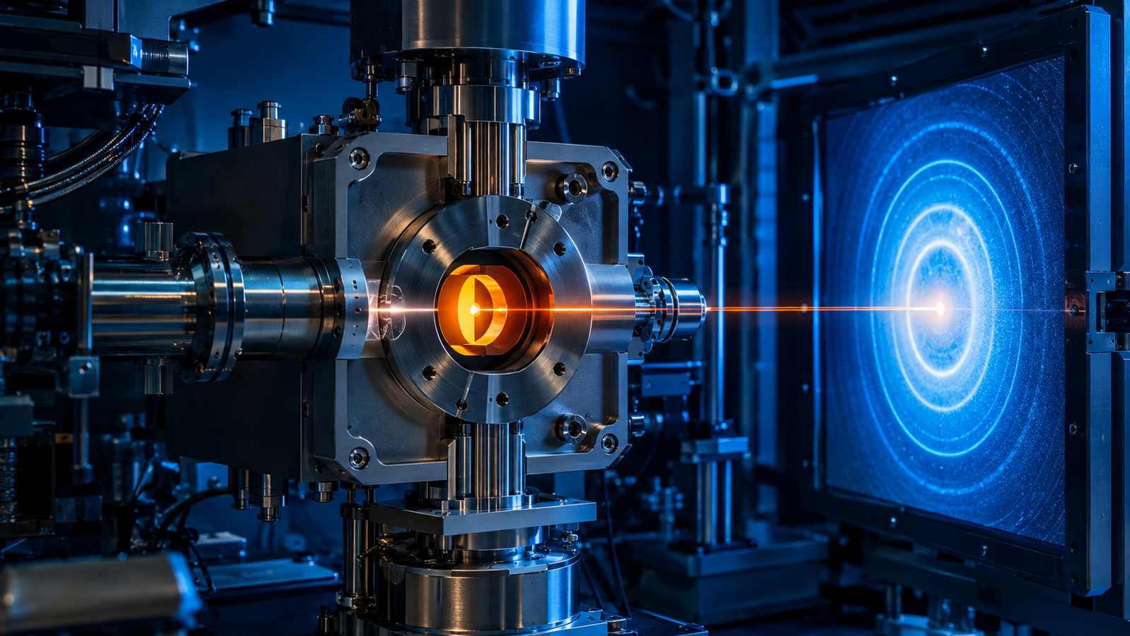
Every laboratory diffractometer has a waiting problem. A pattern takes minutes; a reaction takes seconds; and whatever happened between two exposures is simply gone. The synchrotron answer is brute photon force: park the sample in a storage-ring beam many orders of magnitude brighter than any sealed tube, and a measurement that took twenty minutes can collapse into seconds or below — with the usable frame time still set by the optics, the sample, the cell, the detector, and the counting statistics the analysis needs. Suddenly crystallization, phase transitions, charge cycles, and catalytic switching stop being before-and-after stories and become movies. This guide is about the hardware that makes those movies possible — the compact furnaces and sample cells that hold a specimen at temperature, in a controlled atmosphere, inside one of the most intense X-ray beams on Earth.
1. Why Use Synchrotron In-Situ XRD?
Three currencies matter in any in-situ diffraction experiment: time resolution, penetration, and beam size — and a synchrotron pays out generously in all three. The intense flux means a full powder pattern can be recorded in seconds or less, fast enough to follow structural changes in energy materials, catalysts, and ceramics as they actually happen rather than reconstructing them from quenched snapshots2. The tunable, often high, photon energy passes through millimetres of sample, cell wall, and atmosphere, so the reaction environment travels with the sample into the beam. And a small, well-collimated beam interrogates exactly the volume you care about. The result, in the memorable framing of the field's pioneers, is that you can quite literally watch solids crystallise3.
None of this replaces the laboratory instrument. A lab diffractometer — the workhorse we covered in our guide to in-situ X-ray diffraction — is where methods are developed, temperature programs rehearsed, and slow processes measured in comfort. The synchrotron is where you take the experiment that is too fast, too absorbing, or too small for the lab. Beamtime is scarce and scheduled months ahead; the golden rule of every user program is to arrive with a rehearsed experiment, not an idea. That rehearsal happens at home — on your own instrument, with your own furnace.
| Factor | Laboratory in-situ XRD | Synchrotron in-situ XRD |
|---|---|---|
| Time resolution | Seconds to minutes, depending on the system | Sub-second possible under favourable conditions |
| Photon energy | Fixed source lines (e.g. Cu, Mo) | Tunable; high-energy options available |
| Beam size | Typically larger | Focused and microbeams possible |
| Penetration | Limited by source energy and geometry | High-energy transmission through complex cells |
| Access | Flexible, routine scheduling | Competitive beamtime via proposals |
| Best suited for | Method development, screening, long campaigns | Fast transformations, complex cells, weak signals, operando studies |
Representative comparison only; actual performance depends on the source, optics, detector, sample, cell, and measurement goals.
2. Synchrotron XRD Geometry: Transmission, Capillaries & Windows
The first thing a laboratory crystallographer notices at a powder beamline is that the sample is no longer a flat plate. Most synchrotron powder work runs in transmission — Debye–Scherrer geometry — with the powder sealed in a thin-walled glass, quartz, or sapphire capillary that spins in the beam. Transmission through a rotating capillary averages over many more crystallites, tames preferred orientation, and, crucially for in-situ work, lets a purpose-built flow capillary double as the reaction vessel: gas can flow through it, liquid can fill it, pressure can be applied to it. Purpose-built flow cells extend the idea into a general-purpose sample environment in which temperature, gas composition, and flow are controlled while scattering data stream out4. High photon energies make the geometry generous: even steel-bodied cells and multi-millimetre samples become workable, and operando measurements through real device stacks are routine at dedicated instruments5.
Whatever encloses the sample, the beam must get in and the diffraction cones must get out. Window engineering is therefore a quiet discipline of its own: the material must be X-ray transparent, thermally and chemically stable, and mechanically sound at the operating temperature and pressure difference — a set of constraints that has driven dedicated development of large-area X-ray window technology6. Kapton, beryllium, glassy carbon, aluminium, and thin quartz each occupy a niche; each also contributes its own scattering signature, which a good experiment plan characterizes under representative conditions — a discipline we take apart film by film in our guide to 2θ windows and Kapton films — temperature, atmosphere, geometry — because a single room-temperature empty-cell scan does not describe the background throughout a run.
3. Beamline Furnaces, Cryostats & Sample Cells
Beamline heating hardware has evolved into a small zoo, and the species are best sorted by how the heat reaches the sample. Resistive furnaces surround the capillary or pellet with a heated winding or foil; carefully designed versions reach well above 1000 °C while keeping wide angular openings for time-resolved diffraction7. Radiation furnaces — halogen or infrared lamps, often with elliptical mirrors focusing the light onto the sample — heat without contact, which frees the sample to rotate and translate; designs of this type support even demanding X-ray microscopy techniques at modern beamlines8. The latest generation pushes the concept to remarkable numbers: a contactless furnace recently commissioned at the ESRF reaches 1000 °C with heating rates beyond 6000 °C min−1, stability of about ±2 °C, and full 360° rotational freedom for diffraction and imaging alike9.
The same logic runs downward in temperature — cryostats purpose-built for synchrotron powder diffraction combine sample rotation with a controlled gas atmosphere in the cold space10 — and outward in scope: dedicated sample chambers integrate heating, atmosphere, and precise positioning into one vacuum-tight unit engineered around a specific beamline's geometry11, and cells for surface-sensitive, grazing-incidence work on thin films add their own window, incidence-angle, and sample-positioning constraints12. It is worth noting what beamline hardware deliberately gives up: the roomy, large-volume controlled-atmosphere furnaces of laboratory diffraction13 trade away compactness that a crowded diffractometer circle simply does not have. Beamline furnaces are small because everything around the sample — incident optics, flight tubes, detectors, robots — is fighting for the same few centimetres.
| Sample environment | Strength | Main constraint | Typical use |
|---|---|---|---|
| Resistive capillary furnace | Stable, compact, gas-flow capable | Capillary and temperature-gradient limits | Reactions, phase transitions |
| Infrared / radiant furnace | Very fast, very hot, non-contact | Calibration and optical access | Melting, solidification |
| Cryostat | Deep sub-ambient temperatures | Cooling time, vibration, vacuum integration | Low-temperature phases |
| Operando flow cell | Controlled reactive atmosphere | Background and window absorption | Catalysis, gas reactions |
| Electrochemical cell | Real device operation | Complex background and geometry | Battery cycling |
Representative environments; every beamline maintains its own pool with its own interfaces.
4. Time-Resolved Diffraction and Crystallization Kinetics
The signature synchrotron experiment is the one where chemistry happens on camera. Hydrothermal syntheses followed in real time inside pressurized vessels showed crystalline intermediates appearing and vanishing on the way to the final product — phases no quench-and-grind study had ever caught14. Classic phase-transition work, such as following the polymorphic transformations of potassium nitrate by synchrotron powder diffraction, established the template: heat, watch every reflection, and let the pattern sequence tell the mechanistic story15. The same approach quantifies technology: in-situ high-temperature diffraction of early-stage crystallization in lithium aluminosilicate glass ceramics turns a furnace schedule into rate data16.
Turning a stack of patterns into kinetics usually runs through the Avrami description of nucleation-and-growth transformations, in which the transformed fraction follows x(t) = 1 − exp[−(kt)n] where, under ideal nucleation-and-growth assumptions, the exponent n reflects the combined contributions of nucleation behaviour and growth dimensionality17 — a diagnostic, not a unique mechanistic fingerprint, especially for non-isothermal or overlapping transformations. Fitting hundreds of sequential patterns one by one is the slow way; parametric Rietveld refinement fits the whole series against a single evolving model and can build kinetic expressions directly into the refinement18.
The simulator below makes the core trade-off tangible. It runs the same model α→β transformation — Avrami-type kinetics with an Arrhenius rate constant — under two light sources. In laboratory mode, each diffraction frame needs a long exposure, so the movie is sparse and noisy: ramp fast and the entire transformation can fall between two frames. In synchrotron mode the flux is high, exposures shrink to a fraction of a second, and the same transformation resolves into a clean S-curve with the old phase's peaks fading as the new phase's peaks grow. Counting statistics do the honest work here: noise scales roughly with the inverse square root of the collected photons, so more flux per second buys either faster frames or cleaner ones — the choice that defines every time-resolved experiment. Drag the ramp rate up and watch which source keeps up.
5. Operando Batteries and Catalysts at the Beamline
The word operando — structure measured while the device does its job — was practised before it was named. Dynamic X-ray diffraction of a working electrochemical cell was demonstrated as early as the 1970s19, and the battery community has since converged on standardized beamline hardware: the AMPIX cell, developed at the Advanced Photon Source, cycles a real electrode stack between rigid X-ray-transparent windows while diffraction, pair distribution function, small-angle scattering, or absorption spectra stream out, and it has become a workhorse across multiple beamlines20.
Catalysis added its own twist: because an active catalyst is often part crystalline, part disordered, the field pioneered cells that combine X-ray diffraction with X-ray absorption spectroscopy and on-line product analysis in a single experiment, so structure and function are recorded on the same clock21. In-situ diffraction has since become a basic tool of oxide and metal-oxide catalyst research, tracking reduction, phase changes, and sintering under reaction atmospheres22. The synchrotron is where these methods run fastest, but the discipline transfers home: modern laboratory instruments now run credible operando powder diffraction between beamtimes23 — which is exactly how a well-run program uses them, rehearsing at home and spending photons on the runs that need them.
6. Fast Area Detectors and Synchrotron Data Pipelines
Fast furnaces would be pointless without fast eyes. The decisive step was the hybrid photon-counting pixel detector — single-photon counting, essentially zero readout noise, and millisecond-scale full-frame readout — established at synchrotron sources by the PILATUS family and now standard equipment at powder and scattering beamlines worldwide24 — though the usable frame time still folds in the exposure itself, the count rate, and the statistics the analysis needs. Pair the detector with high-energy X-rays and whole new measurement classes open: rapid-acquisition pair distribution function analysis collects total-scattering data suitable for local-structure analysis in roughly one to tens of seconds per pattern under suitable high-energy conditions25, putting amorphous intermediates and nanoscale disorder on the same movie reel as the crystalline phases.
The price of speed is volume. A time-resolved run produces thousands of patterns, and the crystalline sequences still answer to the same quantitative framework — sequential or parametric whole-pattern Rietveld refinement26 — while total-scattering and PDF data run their own reduction-and-modelling pipeline. Next-generation storage rings compound the challenge, with projected data rates that make automated reduction pipelines part of the experiment rather than an afterthought1. Plan the analysis before the beamtime; the data will not wait politely afterwards.
7. Sample Temperature Calibration at the Beamline
Every rule about controller temperature versus sample temperature applies with extra force at a beamline. The control sensor usually sits near the sample — in the heater body or the gas stream — rather than in the beam-probed volume itself; gradients along a capillary can be steep; and an intense focused beam deposits its own heat in absorbing samples. The elegant fix is that a diffraction experiment carries its own thermometer: lattice parameters change with temperature in a material-specific, calibrated way, so an internal standard mixed with the sample — or a well-characterized phase transition of the sample itself — reads out the true temperature at the exact spot the beam probes. The newest beamline furnaces are calibrated precisely this way, tracking the iron body-centred-to-face-centred transition under beam conditions — repeat transition onsets reproduced within about ±5 °C, with the controller-to-sample relationship remaining specific to the material, mounting, and furnace geometry: a calibration to redo per experiment, not a universal constant9.
The method has range and a sense of humour. Thermal expansion is not even required to be positive: zirconium tungstate famously contracts smoothly from 0.3 to 1050 K, a behaviour mapped by exactly this kind of variable-temperature diffraction27 — and a reminder that the lattice-parameter thermometer must be calibrated per material, not assumed. Whatever standard you choose, measure it in your cell, in your gas, at your ramp rate; a calibration inherited from a different geometry is a guess wearing a lab coat.
8. How to Choose a Beamline-Ready Furnace
Beamtime punishes improvisation. A furnace that works beautifully on the home diffractometer can fail a beamline for reasons that have nothing to do with heating — it shades the detector, it cannot mount on the goniometer, its controller cannot be scripted from the hutch. Five questions sort most of it out in advance:
Five questions before taking a furnace to the beamline
On the hardware side, this is exactly the design brief behind the AIH1600-SR synchrotron IR furnace: infrared radiation heating from room temperature to 1600 °C, ramp rates up to 30 °C s−1 for genuinely time-resolved programs, ±0.5 °C stability, and transmission optics running from a φ15 mm Kapton entrance window to a φ130 mm exit aperture — a broad downstream angular field for beamline integration — around a φ10 mm platinum sample stage in a vacuum/atmosphere chamber. The vacuum system itself is an option, and the final configuration is confirmed against your specific beamline at quotation. The furnace is built to hold melting, solidification, and phase-transition experiments in an intense beam. It belongs to the same InSitu Pro™ heating and cooling stage family that spans optical, electrical, tensile, XRD, and SEM platforms from −190 °C to 1700 °C, so the beamline campaign and the home-lab rehearsal can run on matching thermal logic. For a structured walk through the whole line, the stage selection guide applies the five-question discipline to every family.
9. FAQ
Q. What actually makes synchrotron in-situ diffraction different from the lab version?
Flux, energy, and optics together. The diffraction physics is identical; what changes is many orders of magnitude more photons per second, plus tunable — often high — photon energy, focused beams, and detectors fast enough to use them. Flux buys shorter exposures; the energy reach and the small beams come from the source and its optics, not from flux itself.
Q. Which experiments are worth a beamtime proposal?
The ones the lab cannot do: transformations completing in seconds or minutes, weak or transient intermediate phases, samples buried inside cells or device stacks, total-scattering studies of disorder, and campaigns that need many temperature-composition points in a single shift. Slow, well-behaved processes are usually better science at home.
Q. Capillary or flat plate?
For powder transmission work, usually a spinning capillary: it averages orientation and matches how most powder beamlines are configured — but it is not a universal default. Flat plates, pellets, thin films, device stacks, and dedicated reaction cells all have their beamlines; choose by geometry, absorption, atmosphere, and the angular coverage the science needs.
Q. Can I bring my own furnace to a beamline?
Often yes, and many groups do — but only after checking mounting geometry, beam height, angular openings, cable and gas feedthrough routing, and remote-control interfaces against that specific beamline's documentation. Facilities also maintain sample-environment pools; the practical choice is frequently a hybrid of their positioning hardware and your reaction environment.
Q. How much data should I expect?
Plan for thousands of patterns per shift — a frame every second for a few hours is ordinary, and fast detectors can multiply that by an order of magnitude. Automated reduction and a fitting strategy (sequential or parametric Rietveld) should be tested on rehearsal data before the run, not invented afterwards.
10. Keep Exploring the InSitu Pro™ Knowledge Hub
- In-Situ Heating, Cooling & Electrical Stages: A Theory Guide — the physics foundation for the whole temperature-stage family.
- In-Situ XRD: Watching Crystal Structure Evolve — the laboratory-diffraction companion to this guide.
- Non-Ambient XRD Attachments: Heating, Cooling & Vacuum — choosing the chamber that surrounds the sample.
- InSitu Pro™ heating & cooling stages — the full temperature-stage platform from −190 °C to 1700 °C.
- InSitu Pro™ Stage Selector — answer five questions and shortlist a stage with one-click quote.
References
This article is provided by ACS Material LLC for educational purposes and describes in-situ experiments at synchrotron beamlines — transmission diffraction geometry, beamline furnaces and sample cells, time-resolved and operando methods, detectors, and temperature calibration. Flux comparisons, frame times, temperature ranges, and heating rates cited refer to representative facilities, published designs, and the specific studies referenced; the capabilities of any given beamline or furnace depend on the source, optics, detector, model, options, and sample. Sample temperature can differ from the controller setpoint and should be validated against an internal diffraction standard or certified reference under the actual experimental conditions. The interactive simulator on this page is a schematic teaching tool built on idealized models — representative peak positions, Avrami kinetics with fixed exponents, and Poisson-like noise scaling — not a substitute for measurement or beamline documentation. For product-specific specifications, always consult the relevant technical data sheets and safety data sheets, or contact our team to confirm fit against your beamline and experiment.