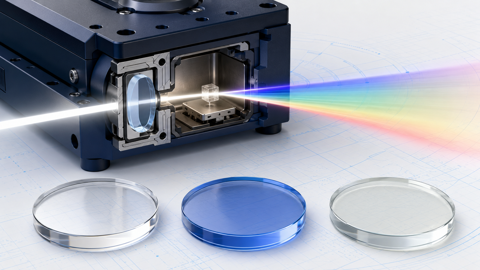
Every in-situ heating or cooling experiment that uses light — a microscope, a Raman spectrometer, an infrared beam — has to look at the sample through something. That something is the optical window: a thin transparent plate that seals the sample inside a controlled-temperature, controlled-atmosphere chamber while letting the measurement beam pass in and out. It is easy to treat the window as an afterthought, but it is an optical component in the beam path, and the wrong choice quietly costs signal, resolution, and sometimes the whole measurement. This guide covers what the window actually has to do, how quartz, sapphire, calcium fluoride and Kapton differ across the spectrum, and how refractive index, birefringence, Raman background and thermal shock decide which one belongs on your stage.
1. Why the In-Situ Window Is a Real Optical Component
A sealed in-situ stage exists to hold a sample somewhere it would not naturally sit still — at 600 °C, at −190 °C, under vacuum, or in a reactive gas — while a measurement is taken. The moment that measurement uses light, the seal has to become transparent, and that transparent patch is the window. Unlike the walls around it, the window sits directly in the optical path, so every property it has is inherited by the measurement: its transmission sets how much light survives the round trip, its refractive index and thickness bend and displace the beam, its own vibrational and electronic structure adds background to a spectrum, and any birefringence it carries scrambles polarization. A window is therefore not packaging; it is a lens, a filter, and a potential noise source rolled into one thin plate.
The demands pull in different directions, which is exactly why no single material wins. A window has to be optically good in the band you care about, but it also has to be mechanically and thermally good enough to survive being clamped over a chamber that swings through hundreds of degrees and, often, holds a pressure difference against vacuum. Push for the widest infrared transmission and you may land on a soft, thermal-shock-sensitive crystal; push for ruggedness and you may sacrifice deep-UV or mid-IR reach. The rest of this guide is really a tour of those trade-offs, material by material and property by property, so that the window on your stage is chosen rather than inherited.
2. The Window Material Family: Quartz, Sapphire, CaF2 & Kapton
Four representative materials are the ones most frequently encountered in in-situ optical and X-ray stage design, each occupying a different niche defined by the spectrum it passes and the environment it survives. They are not the only options — magnesium fluoride, barium fluoride, zinc selenide, silicon, germanium, diamond and various optical glasses each serve specialized bands — but these four cover the common ground. Understanding their personalities is the foundation for everything that follows.
- Fused silica (quartz). The default optical window. Amorphous silicon dioxide with excellent transparency from the ultraviolet through the near-infrared, very low fluorescence, a low thermal-expansion coefficient that makes it superbly thermal-shock resistant, and enough hardness and chemical inertness to survive most stage environments. It is the workhorse precisely because it is good at almost everything and bad at almost nothing1. Both "fused quartz" and "fused silica" denote the non-crystalline (amorphous) melted form — true crystalline quartz is birefringent and is a different material — but in commercial optics the two terms often flag different feedstock: fused quartz is commonly made from natural quartz, whereas synthetic fused silica is grown from chemical precursors and can reach higher purity, so impurity content, OH concentration and UV/NIR performance vary by grade.
- Sapphire (single-crystal Al2O3). The rugged specialist. Extremely hard and scratch-resistant, chemically almost inert, and transparent over a remarkably broad band from the UV at about 0.15 µm out to roughly 5.5 µm in the mid-infrared2. Its combination of strength and thermal endurance makes it the choice for high-pressure, high-temperature or abrasive environments — at the cost of being a birefringent crystal that must be cut on the right axis for polarization work.
- Calcium fluoride (CaF2). The spectroscopist's window. A cubic crystal transparent over an exceptionally wide range — roughly 0.13 to 10 µm, from the vacuum-UV deep into the infrared, depending on grade, thickness and the transmission threshold used — with a low refractive index and very low dispersion3. Being cubic, it is optically isotropic, so it carries no intrinsic birefringence, and Raman-grade material shows almost no fluorescence. Its weaknesses are mechanical: it is soft, cleaves easily, and is sensitive to thermal shock.
- Kapton (polyimide film). The thin, flexible, X-ray-friendly outlier. A polymer film rather than a rigid crystal, prized in diffraction and X-ray work for its low X-ray absorption and mechanical toughness. Optically, though, it is deeply coloured: an 80-µm Kapton film is a deep amber with an absorption edge near 550 nm, so it transmits poorly in the blue and UV and is unsuitable as a visible or UV optical window4. It appears here mainly to explain why the window that is standard for XRD stages is the wrong window for optical microscopy.
| Material | Transmission (approx.) | Optical class | Birefringence | Toughness | Typical niche |
|---|---|---|---|---|---|
| Fused silica (quartz) | ~0.18–2.5 µm | Amorphous, isotropic | None (stress-induced only) | Good; excellent thermal shock | General UV–VIS–NIR workhorse |
| Sapphire (Al2O3) | ~0.15–5.5 µm | Uniaxial crystal | Weak, intrinsic (cut-dependent) | Very high; hard, rugged | Harsh, high-pressure, broadband |
| Calcium fluoride | ~0.13–11 µm | Cubic crystal, isotropic | None (stress-induced only) | Low; soft, thermal-shock sensitive | VUV & IR spectroscopy, low-background Raman |
| Kapton (polyimide) | Poor <450 nm; NIR/IR & X-ray | Polymer film | Stress-induced (biaxial film) | Flexible, tough film | XRD & X-ray windows, not visible optics |
Representative bulk-material ranges only. UV-grade, IR-grade and Raman-grade variants shift the useful band, and the usable range of a mounted stage window depends on grade, thickness, coatings, temperature, atmosphere and the system optics. Values are for orientation, not specification.
3. Transmission Range: From the Ultraviolet to the Infrared
The first question to ask of any window is brutally simple: does it pass the wavelength I am using? Every transparent material has a transmission window bounded on the short-wavelength side by electronic (band-gap) absorption and on the long-wavelength side by lattice-vibration (phonon) absorption. Between those two walls the material is clear; outside them it is effectively opaque. Choosing a window starts with laying your working wavelength inside that clear band with margin to spare.
For fused silica the clear band runs from about 180 nm in the UV to roughly 2.5 µm in the near-infrared for standard grades, with the exact edges set by grade and purity1. A crucial subtlety hides in the near-infrared: ordinary "wet" fused silica contains hydroxyl (OH) impurities that produce absorption bands around 1.4, 2.2 and 2.7 µm, so UV-grade silica — low in metallic impurity but high in OH — transmits beautifully in the UV yet shows dips in the NIR, while IR-grade silica reverses the trade by removing OH at some cost to UV reach5. If your experiment sits near 2 µm, the OH content of the specific grade matters more than the nominal "fused silica" label.
Sapphire extends further into the mid-infrared, transmitting from about 0.15 µm in the UV to roughly 5.5 µm, which is why it is favoured when an experiment needs both a rugged window and reach past where silica cuts off2. Calcium fluoride is the transmission champion of the group, clear from roughly 0.13 µm in the vacuum-UV out to about 10 µm in the infrared (the exact edges depend on grade, thickness and threshold), covering spectral regions neither silica nor sapphire can reach36. That breadth, combined with very low dispersion, is exactly why CaF2 is the standard substrate for UV and IR spectroscopy despite its mechanical fragility.
Kapton is the instructive counter-example. Its deep amber colour is not a coating or a contaminant — it is intrinsic. The colour arises from charge-transfer complexes between the electron-donor and electron-acceptor units of the polyimide backbone, which absorb strongly in the UV and blue; an 80-µm film has an absorption edge (cut-on) near 450–550 nm and transmits only about 80% even in the red, with an optical band gap of roughly 2.2 eV4. Polyimide is itself photoelastically active — its stress-optic coefficient has been measured at around 400 nm per MPa per centimetre — so even as a film it develops stress birefringence when biaxially tensioned7. That makes Kapton a poor choice for quantitative visible or UV optics — though a thin film may still pass some red or near-infrared light — yet its low X-ray absorption and mechanical toughness make it the standard window for X-ray diffraction stages, a neat illustration that "transparent" always means "transparent to what." The window that is right for watching a Bragg pattern evolve is generally the wrong window for watching a crystal melt under a microscope.
4. Interactive: Stress Birefringence in a Sealed Window
A window sealed over a chamber that holds vacuum, or that swings through a wide temperature range, is not stress-free. The pressure difference across it and the constraint of its mounting put the plate under mechanical stress — and stress makes even an isotropic material optically anisotropic. This is the photoelastic effect: under load, the refractive index a light ray sees depends on its polarization direction, so a linearly polarized beam picks up a phase difference (a retardation) between its two components. For polarization-sensitive measurements, that retardation is a direct error source. Set the window material, thickness and assumed in-plane principal stress difference in the model below, then watch the estimated retardation — and the crossed-polarizer leakage it would produce — grow and shrink. The model takes the resulting stress as its input; it does not convert a pressure difference into a stress field, which requires a structural model of the specific window.
The physics is the stress-optic law. For a window of thickness h carrying a difference (σ1−σ2) between its two in-plane principal stresses, the optical retardation is δ = C · h · (σ1−σ2), where C is the material's stress-optic coefficient8. Note that this principal-stress difference is not the same as the gas pressure difference across the window: turning a pressure load into an actual stress field requires a structural (plate or membrane) model of the window's diameter, thickness, edge support and mounting. The coefficient is measured by tracking retardation between crossed polarizers under a known load9; for fused silica C is about 3.5 × 10⁻¹² Pa−110 — roughly 4 nm of retardation per millimetre of thickness per megapascal of stress — so the effect is small but not negligible: a 25-mm-thick part under 1 MPa can accumulate on the order of 100 nm of retardation, a meaningful fraction of a wavelength11. The practical lesson is that thinner windows and low-stress mounting both reduce the problem, and that for demanding polarization work the window and its mount are part of the optical design, not hardware details.
5. Refractive Index, Dispersion & Working Distance
Once a wavelength passes the window at all, the next question is how the window bends and delays it. A flat window does not focus light, but it is a slab of high-index material in the path, and that has three consequences an experimentalist feels directly: it displaces the focus, it can introduce aberration, and it eats into the objective's working distance.
The refractive indices of the common window materials span a useful range. Fused silica sits near 1.46 in the visible, described across its whole band by Malitson's classic Sellmeier dispersion equation1, with its small temperature dependence characterized down to cryogenic temperatures12. Calcium fluoride is lower, about 1.43 at 589 nm, with notably low dispersion — one reason it doubles as an achromatic lens material3. Sapphire is higher, around 1.76 in the visible, and because it is birefringent it actually has two indices (ordinary and extraordinary) that differ by about 0.0082. A lower-index window like CaF2 reflects less at each surface — low enough that it is often usable uncoated — while a higher-index window like sapphire loses more to Fresnel reflection unless anti-reflection coated. CaF2's low index gives it high uncoated transmission across a broad band, part of why it is a staple spectroscopic window6.
The working-distance issue is the one that most often bites in practice. A high-numerical-aperture objective focuses a steep cone of light, and any flat plate of glass in that cone introduces spherical aberration unless the objective is designed for exactly that plate thickness — the same reason microscope objectives specify a cover-glass thickness, conventionally 0.17 mm. Deviating from the design thickness degrades the image, and the effect worsens sharply as numerical aperture rises above about 0.7. An in-situ window is thicker and further from the sample than a cover slip, so two things follow: the objective must have a long enough working distance to reach the sample through the window and the gas gap, and, optically, a thinner window usually reduces absorption and plate-induced aberration. Thinner is not automatically better in every respect, though — the final thickness must also satisfy strength, deflection, wavefront-quality, thermal-gradient and mounting-stability requirements, so thickness and clear aperture have to be designed together. This is why in-situ optical stages are built around long-working-distance objectives and the thinnest window the pressure, temperature and wavefront budget will allow.
6. Birefringence & Polarized Light: Why the Crystal Axis Matters
Polarized light is one of the most powerful tools in optical microscopy and in-situ spectroscopy — it is how birefringent crystals are told apart from isotropic liquids, how liquid-crystal textures are read, and how stress and orientation are mapped. But polarized measurements are only as clean as the window they look through, because a birefringent window will rotate and scramble the polarization state before the light ever reaches the sample. Understanding which windows are birefringent, and why, is essential for any polarization-sensitive stage.
The distinction comes straight from crystal symmetry. An amorphous material like fused silica has no long-range order and no preferred direction, so it is optically isotropic — one refractive index for every polarization — and carries no intrinsic birefringence1. A cubic crystal like calcium fluoride is also optically isotropic by symmetry: its high crystal symmetry makes the refractive index the same along every axis, so CaF2, too, is intrinsically birefringence-free313. These two are the natural choices when polarization purity matters most.
Sapphire is different. It is a uniaxial crystal, meaning it has a single special direction — the optic axis, or c-axis — and light polarized perpendicular versus parallel to that axis sees different refractive indices. The difference is small, about 0.008, but it is enough to introduce retardation and disturb a polarization measurement214. The elegant fix comes from the geometry: along the optic axis itself, the two indices coincide and the birefringence vanishes. So a sapphire window cut with its c-axis perpendicular to the face — called c-cut, z-cut, or "zero-degree" sapphire — presents its optic axis to a near-normal, paraxial beam, which then travels close to the axis and experiences greatly reduced birefringence. This is why c-cut sapphire is usually preferred over an arbitrary orientation for polarization-sensitive work. It is not a guarantee of polarization neutrality, though: a high-numerical-aperture cone contains many oblique rays, and oblique incidence, edge rays and mounting stress can all still introduce measurable retardation, so the full illumination cone and the mount need to be evaluated14. A randomly oriented sapphire window is fine for simple transmission but will corrupt crossed-polarizer work.
There is a second, sneakier source of birefringence that affects every material, even the isotropic ones: mechanical stress, through the photoelastic effect explored in the simulator above. An intrinsically isotropic fused-silica or CaF2 window becomes weakly birefringent when it is clamped too tightly or loaded by a pressure difference, and although a cubic crystal such as CaF2 carries no intrinsic birefringence, its stress-induced birefringence can still be orientation-dependent10. So the recipe for a clean polarization window is twofold: start with an intrinsically isotropic material (silica or CaF2) or a correctly cut uniaxial one (c-cut sapphire), and mount it with low, symmetric stress so the photoelastic contribution stays negligible.
7. Raman & Fluorescence Background: When the Window Talks Back
Raman spectroscopy is a favourite in-situ probe because it reports chemical bonds directly and needs no contact. But Raman signals are weak, and anything in the beam path that scatters or fluoresces competes with the sample. A window is directly in that path, so its own Raman bands and fluorescence set a background floor that the sample signal has to rise above. For an in-situ Raman stage, the spectral cleanliness of the window is a first-order concern, not a detail.
The materials differ sharply. Calcium fluoride is often an excellent low-background choice for Raman work, and is widely treated as a benchmark substrate: Raman-grade CaF2 typically shows very low fluorescence in a suitable optical grade and has just a single narrow Raman band near 320–330 cm−1, in a low-wavenumber region where most functional-group vibrations of interest do not sit — so it rarely obscures the bands you actually want15. No window is universally clean, though, and the right one should be confirmed at the intended laser wavelength, spectral range, focus and temperature15. Fused silica is also usable: in suitable grades it shows generally low fluorescence, and its most prominent Raman activity is confined below about 900 cm−1, leaving a relatively clean window above 1200 cm−1 — though those broad silica Raman bands below 900 cm−1 can overlap parts of the spectrum, a more crowded region than CaF2's single line15. Ordinary optical glass can contribute a broad Raman band around 1400 cm−1 plus a fluorescence background that overlaps the fingerprint region and can swamp weak analyte features; it should be characterized experimentally and is usually avoided when low-background quantitative Raman is needed15.
Sapphire deserves a specific warning. It has sharp, well-known Raman lines of its own, and more importantly it can show a strong fluorescence background that depends on excitation wavelength and on trace impurities — the fluorescence in Al2O3 is attributed largely to iron and chromium impurities and can be intense under near-infrared (for example 1064 nm) excitation16. A rugged sapphire window that is perfect mechanically can therefore be a poor Raman window if its impurity-driven fluorescence lands on your bands. The general strategy is to pick the window for a clean region at your excitation wavelength, and to remember that the "best" window for Raman (CaF2) and the "best" window for ruggedness (sapphire) are often not the same plate.
| Window | Photoluminescence | Own Raman signature | Raman verdict |
|---|---|---|---|
| Calcium fluoride (Raman grade) | Essentially none | Single narrow band ~320–330 cm−1 | Gold standard — cleanest |
| Fused silica (quartz) | None | Activity below ~900 cm−1; clean above ~1200 cm−1 | Good, especially high-wavenumber |
| Sapphire | Impurity-driven (Fe, Cr); strong at 1064 nm | Sharp intrinsic lines | Use with care; wavelength-dependent |
| Ordinary glass | Often significant | Broad band ~1400 cm−1 | Usually avoided for low-background Raman |
Backgrounds depend on excitation wavelength, grade and impurity level. Always test the specific window at the working laser line.
8. Thermal Shock, Pressure & Mechanical Survival
An in-situ window has to survive the environment as well as pass the light. Two mechanical demands dominate: surviving rapid temperature change without cracking (thermal shock) and holding a pressure difference — often a full atmosphere against vacuum — without failing. These constraints frequently override optical preferences, because a window that cracks mid-experiment ends the measurement regardless of how clean its spectrum was.
Thermal shock is the more subtle threat. When a window's surface changes temperature faster than heat can conduct through it, the surface and interior expand by different amounts, generating internal stress; if that stress exceeds the material's strength, existing surface flaws propagate into cracks. The classic analysis of this failure, Hasselman's unified theory of thermal-shock fracture, expresses a material's resistance in terms of a critical temperature difference ΔTc it can tolerate before cracking — a quantity that rises with fracture strength and thermal conductivity and falls with thermal-expansion coefficient and elastic modulus17. A low thermal-expansion coefficient is the single biggest lever — it means small differential strain for a given temperature jump — but it is not the whole story: thermal-shock resistance also depends on thermal conductivity, elastic modulus, strength, fracture toughness, the flaw population, geometry and the heat-transfer conditions.
This is exactly where fused silica excels. Its very low thermal-expansion coefficient gives it outstanding thermal-shock resistance — it can take rapid temperature swings that would shatter many other materials — which, combined with its broad transmission, is a large part of why it is the default in-situ window17. Sapphire is mechanically the strongest of the group, very hard and able to hold large pressure differences — which is exactly why sapphire viewports are chosen for high-pressure, high-temperature optical cells18 — though its higher expansion coefficient makes it somewhat less forgiving of sudden thermal shock than silica. Calcium fluoride is the fragile one on both counts: it is soft, it cleaves along crystal planes, and it is notably sensitive to thermal shock, so CaF2 windows must be ramped gently and handled carefully despite their superb optical properties.
Pressure sets a second requirement. A window sealing vacuum must not deflect or fail under the load, which for a given material and diameter means a minimum thickness — and here the mechanical demand collides head-on with the optical preference for thinness from Section 5. The resolution is an engineering compromise: choose a strong enough material that the required thickness stays modest, support the window well at its edge, and match the thermal expansion of the window to its mount so that heating does not clamp or crack it. As the ultra-high-vacuum community has documented, low, symmetric mounting stress is also what keeps stress-birefringence negligible — so good mechanical design and good polarization performance turn out to be the same design goal19.
9. How to Choose an Optical Window: Five Questions
Every property in this guide collapses into a short decision procedure. Answer these five questions in order and the material almost always chooses itself — and where two materials tie, the tie-breaker is usually thermal shock or Raman background.
In practice the answers cluster. A great many in-situ optical and Raman stages end up on fused silica because it satisfies questions 1, 2, 4 and 5 simultaneously for visible-to-near-IR work — broad transmission, isotropic, thermal-shock resistant, and available thin — while CaF2 is reached for when the spectrum demands the vacuum-UV or the mid-IR or the very lowest Raman background, and sapphire when the environment is simply too harsh for anything softer. There is rarely a single perfect window; there is a best window for your five answers.
How this maps to ACS InSitu Pro™ optical stages
On ACS InSitu Pro™ optical heating-and-cooling stages, the standard optical access is a quartz-glass (fused-silica) window — the workhorse choice that satisfies most of the five questions above for visible-to-near-IR microscopy and Raman:
- ACH600S — atmosphere optical heating & cooling. −190 to 600 °C, quartz-glass optical window with a specified 220–2500 nm range; top window Ø25 × 1 mm, optional bottom window Ø10 × 1 mm, window-to-stage distance 4.5 mm.
- ACH400SV — vacuum optical heating & cooling. −190 to 400 °C in a vacuum chamber, using the same quartz-glass optical-access concept.
- ACH600S-T / ACH400SV-T — tight optical geometry. A 21.5 mm body height and 4.8 mm window-to-stage distance for more space-constrained optical instruments.
To see the full optical stage line-up and match a configuration to your instrument, browse the InSitu Pro™ optical-application stages, or answer five questions in the InSitu Pro™ Stage Selector.
10. Frequently Asked Questions
11. Keep Exploring the InSitu Pro™ Knowledge Hub
The optical window is one interface in a larger in-situ toolkit. These guides connect window choice to the stages, techniques and physics around it:
- In-situ heating, cooling & electrical stages: a theory guide — the shared physics of sample temperature, thermal lag and controlled environments that every windowed stage is built on.
- Variable-temperature Raman spectroscopy: a practical guide — where the Raman-background properties of the window in Section 7 matter most, alongside laser and temperature control.
- Hot-stage microscopy: watching melting, crystallization & phase change — the polarized-light technique that depends directly on an isotropic, low-stress optical window.
- XRD stage windows: 2θ geometry & Kapton films — the other kind of window, seen from the X-ray side, and why Kapton is standard there but wrong for optics.
- InSitu Pro™ Optical Heating & Cooling Stage (ACH600S / ACH400SV) — the product page for the optical stage whose quartz window is designed around exactly these trade-offs.
- How to choose an in-situ heating & cooling stage — the five-step selection guide, with two interactive simulators and a live stage selector, that puts window choice in the context of the whole stage decision.
- InSitu Pro™ Stage Selector — answer a few questions and get matched to the stage and window configuration that fit your experiment.
References
This article discusses optical windows — fused silica (quartz), sapphire, calcium fluoride and Kapton polyimide — for in-situ heating and cooling stages in general terms. Transmission ranges, refractive indices, birefringence, Raman backgrounds and thermal-shock behaviour are idealized and grade-dependent; real values vary with material grade, purity, thickness, coating and supplier, and should be confirmed against the manufacturer's datasheets and the specifications of your specific stage and objective before designing an experiment. The interactive simulator is a schematic teaching tool that illustrates the stress-optic relationship and is not a substitute for a proper finite-element stress analysis or optical-design calculation.