
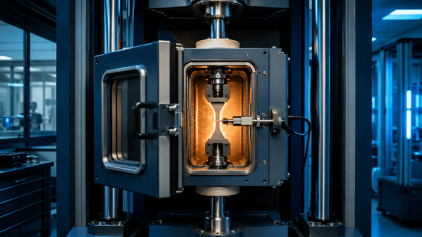
There are two roads to a stress–strain curve at −150 °C or +600 °C. One is the compact route the in-situ tensile testing guide describes: a desktop stage with temperature built in, sitting under a microscope. The other starts from the machine you already own — a full-size universal testing machine (UTM) with its calibrated load cells, its grip library and its decades of validated procedure — and adds the temperature axis as a module: an environmental chamber or furnace that wraps the specimen while the frame keeps doing what it does best. This article is the module road’s field guide: what a UTM temperature module actually consists of, why the specimen’s temperature is not the chamber’s, which standards govern hot and cold tensile work, and how to budget the errors that the temperature axis smuggles into a mechanical test.
1. Two Roads to Hot and Cold Mechanical Testing
The decision between a temperature-integrated desktop stage and a module on a big frame is mostly decided by three questions. How much force? Compact desktop stages such as the AFCH500-200 cover forces up to 500 N, and other dedicated in-situ tensile stages in the family reach the 5000 N class; full-size frames carry kilonewtons to meganewtons, so full-scale standard specimens, a broader force envelope, existing certified fixtures and established laboratory procedure all point to the module road. What specimen? Standard-geometry testing to the letter of the tensile standards families is the big frame’s home turf; films, fibers and micro-coupons under a microscope belong to the desktop route. What observation? If the point is watching microstructure evolve under an objective, the in-situ stage wins by design; if the point is certified mechanical numbers at temperature, the module preserves the load frame’s calibrated force chain and adds climate around it. The two roads are complements, not rivals — many labs run both: the underlying material response is shared, while the measurement systematics differ between the two architectures.
2. Module Architectures: From Full-Frame Chambers to Compact Modules
A. Full-frame environmental chambers and furnaces. Many conventional UTM chambers enclose the working volume with circulating air, radiant elements or furnace insulation; pull rods pass through insulated ports to connect in-chamber grips to the out-of-chamber frame and load cell — the mechanical umbilicals that let force cross the thermal boundary. Cryogenic versions swap heating elements for liquid-nitrogen injection or a cooled exchanger, and the insulation problem inverts: the enclosure fights frost and condensation instead of heat loss. Around this core sit access features — a window for optical strain work, ports for a clip-on extensometer or thermocouple bundle — and the grips themselves become temperature components: hot-side grips need alloys that keep strength at temperature, cold-side grips need toughness where ordinary steels embrittle1.
B. Compact sample-environment modules. A second architecture shrinks the climate to the specimen’s immediate neighbourhood: a conductive (typically copper) temperature-controlled sample stage inside a small atmosphere-capable chamber with an optical top window, mounted onto the host machine. Heating and cooling act through the stage rather than through a large air volume, observation and optical strain measurement go through the window, and the host machine’s force chain stays outside. The generic full-frame features of paragraph A — circulating fans, pull rods, in-chamber grips, grip-body cooling, extensometer penetration ports — should not be assumed on a compact module; each product’s datasheet defines what its architecture actually includes.
3. The Central Problem: Chamber Temperature Is Not Specimen Temperature
The controller on the front panel reports its own sensor — which, depending on the architecture, may sit in the chamber air, the heater body, the sample stage, the grip region or near the specimen; in every case it reports the sensor’s location, not automatically the specimen’s. The specimen is somewhere else thermally, for two structural reasons. First, the mechanical connections are heat paths: pull rods, fixtures or the stage body link the specimen region to room-temperature structure, and conduction along them continuously drains (or feeds) heat at the boundaries, imposing a steady-state gradient whose size is design-dependent — chamber, grip geometry, specimen conductivity, insulation, convection and radiation all enter — and which longer soaking does not necessarily remove, only the transient part. Second, the specimen has thermal mass and lag: after a setpoint change, the air arrives first, the grips later, the specimen core last — so “the chamber has been at 300 °C for ten minutes” is a statement about air. The elevated-temperature tensile standard is explicit on this point: it specifies permitted deviations of the specimen temperature, measured on the specimen, with tolerance bands that tighten the claim from an air reading to a material reading2. The general lesson transfers from every stage article in this hub: temperature claims trace to a calibration chain anchored in the practical scale3, and the last link of that chain must touch the specimen, not the furnace wall.
4. Interactive: The Gradient & Soak Lab
The simulator below turns Section 3 into two read-outs. Set a target temperature and watch the specimen’s core approach it along a lag curve — the soak clock only starts, honestly, when the specimen arrives, not the chamber. Meanwhile the gradient read-out reports the steady temperature difference between the gauge center and the grip ends imposed by pull-rod conduction, and a toggle shows what changing the grip-end thermal anchoring does to it.
Two lessons are built in. The soak time to a ±1 °C criterion grows with the size of the temperature step — and it is a property of the specimen-plus-fixturing thermal mass, not a constant you can memorize, which is why the protocol below says measure the soak rather than assume it. And the gradient scales with the distance between specimen temperature and room temperature: modest at 100 °C, structural at 600 °C or −150 °C. The model is schematic — a single-exponential core approach plus a proportional grip-leak gradient, with parameters chosen for teaching rather than any real chamber — and real modules add convection patterns, radiation and grip-mass asymmetries that only specimen-mounted thermocouples reveal.
5. What Temperature Does to the Test Itself
What temperature does to the material — moduli softening, thermally activated yield collapse, brittle transitions, creep — is the companion article’s territory, with the constitutive frameworks that couple temperature and strain rate4; the variable-temperature tensile guide walks every landmark. What temperature does to the test is this article’s half. Strain measurement leads the list: crosshead displacement now includes the thermal expansion of pull rods and fixtures on top of frame compliance, so gauge-section measurement stops being a nicety — a high-temperature-rated contact extensometer through a port, or optical strain through the window, where digital image correlation brings its full-field power and its hot-side homework of heat haze, speckle survival and radiant glow5. The strain zero moves too: the specimen expands or contracts on the way to temperature (not always in the intuitive direction — negative-thermal-expansion materials contract on heating6), so thermal and mechanical strain must be separated by a near-zero-load hold, with the constraint caveat the tensile guide details. And the force chain itself feels the climate: load-cell temperature sensitivity, grip strength at heat, fixture embrittlement in the cold1 — all reasons the module road keeps the load cell outside the chamber and lets calibrated pull rods carry the force across.
6. The Standards Map: Which Part Governs What
Hot and cold tensile testing is one of the most thoroughly standardized corners of materials science, and the module road exists largely to serve it. The map, for the metallic-materials series most laboratories cite:
| Standard | Scope | Why it matters on the module road |
|---|---|---|
| ISO 6892-17 | Tensile testing at room temperature | The baseline method every temperature part modifies |
| ISO 6892-22 | Elevated temperature | Specimen-temperature tolerances, soak, measurement location |
| ISO 6892-38 | Low temperature (down to −196 °C) | Cryogenic procedure and temperature control requirements |
| ISO/TR 152639 | Uncertainty evaluation in tensile testing | The formal framework for the error budget of Section 7 |
| ISO/TS 6892-510 | Miniaturised test pieces | Where module work meets small-specimen practice |
The ASTM families (E8/E8M and their elevated- and reduced-temperature kin, named here descriptively) cover the same ground for laboratories on that system. The practical point is identical either way: the standards’ temperature clauses are written about the specimen, which is why the module’s job description includes making specimen-mounted temperature measurement possible, not just making the chamber hot or cold.
7. The Error Budget: Where Module Numbers Go Wrong
The temperature terms first, because they are the module’s own contribution: axial gradient along the gauge length (pull-rod conduction), soak shortfall after setpoint changes, the offset between air thermocouple and specimen, and the calibration of whichever sensor finally touches the specimen3. Then the mechanical chain at temperature: pull-rod and fixture thermal expansion contaminating displacement-based strain; load-cell temperature coefficients if the cell sees chamber-adjacent warmth; grip slippage as thermal cycling loosens what was tight; alignment shifts as the chain expands unevenly. Then the measurement optics: window distortion, haze above hot specimens and glow at the top of the range for optical strain work5; extensometer knife-edge behaviour and calibration at the working temperature. The formal machinery for turning this list into a defensible uncertainty statement exists and is worth using9; the blunt version is the tensile guide’s refrain — the systematics deserve the effort before the noise does.
8. A Working Protocol: From Mounting to Reported Curve
1. Instrument the specimen, not just the chamber. At least one thermocouple on the gauge section (per the elevated-temperature standard’s placement guidance); for long specimens or wide ranges, one near each end to see the gradient directly.
2. Map the module once. On a sacrificial or dummy specimen, measure gradient and soak time at the temperatures you will actually use; record them as properties of your chamber-grip-specimen combination.
3. Verify the strain chain at temperature. Extensometer or DIC checked at the working temperature; if displacement must be used, measure the fixture-expansion contribution and say so.
4. Reach temperature at near-zero load. Record the thermal-strain baseline; only then load — the separation discipline of the tensile guide, with the module’s larger fixturing making the near-zero-load hold matter more, not less.
5. Soak to the specimen’s clock. Hold until the specimen-mounted sensors — not the controller — satisfy the standard’s tolerance band2.
6. Report the thermal facts with the mechanical ones. Specimen temperature and its measurement location, gradient if known, soak protocol, atmosphere — alongside rate, geometry and the usual landmarks. The reproducibility test is unchanged: a stranger with your record reaches your numbers unaided.
9. Hardware Notes: Running This on Your Frame
The catalogued InSitu Pro™ entry on the module road is the UTM temperature module (AUCH600 / AUCH600-HT) — a compact sample-environment module in the Section 2B sense: a conductive copper sample stage inside a small atmosphere-capable chamber with an optical top window, bringing the InSitu Pro™ temperature-control discipline to mechanical testing on a host machine. Its standard published specification:
| Item | AUCH600 | AUCH600-HT |
|---|---|---|
| Temperature range | −190 to 600 °C | −190 to 600 °C |
| Stability | ±0.1 °C | ±0.1 °C |
| Max heating / cooling | 100 / 40 °C·min−1 | 100 / 40 °C·min−1 |
| Sample stage | Cu, 30 × 25 mm | Cu, 30 × 50 mm |
| Top window | φ25 × 1 mm JGS2, 220–2500 nm | φ25 × 1 mm JGS2, 220–2500 nm |
| Chamber | Atmosphere | Atmosphere |
| Dimensions | 96 × 70 × 30 mm | 160 × 143 × 83 mm |
| Net weight | 1 kg | 2 kg |
Host-machine mounting, loading fixtures, DIC or video-extensometer arrangement and any alternative chamber configuration are confirmed at quotation. For work the module road does not serve — small specimens under a microscope, correlative imaging during the pull — the AFCH500-200 desktop tensile stage is the integrated alternative, and the stage selector or the selection guide will walk the choice.
- UTM Temperature Module (AUCH600 / AUCH600-HT) — compact −190 to 600 °C sample-environment module for host-machine mounting; standard specification above, mounting confirmed at quotation.
- Desktop Tensile Stage (AFCH500-200) — the integrated compact route: −190 to 200 °C under observation optics.
- In-situ tensile testing at variable temperature — the companion guide to what temperature does to the curve itself.
- All InSitu Pro™ stages — the complete family, or use the interactive stage selector.
10. FAQ: UTM Temperature Modules
11. Keep Exploring the InSitu Pro™ Knowledge Hub
This article extends the mechanical-testing wing of the InSitu Pro™ knowledge hub. To keep going:
- In-situ heating, cooling & electrical stages: a theory guide — the pillar article on temperature control, lag and stability.
- In-situ tensile testing at variable temperature — the curve-side companion: what temperature does to every landmark.
- In-situ SEM heating stages — electron-microscope integration for watching mechanisms at magnification.
- In-situ XRD: watching crystal structure evolve — the diffraction partner for lattice strain and phase change.
- How to choose an in-situ heating & cooling stage — the five-step selection guide.
References
This article discusses UTM temperature modules and hot/cold mechanical-testing methodology in general terms. Gradient magnitudes, soak behaviour, tolerance interpretations and fixture performance are idealized and depend on the chamber, frame, grips, specimen, atmosphere and instrumentation; real values must be established experimentally and validated against the applicable standards, the published literature, your own calibrations and the manufacturer’s datasheets before quantitative use. The interactive simulator is a schematic teaching tool built on a stated illustrative model, not measured data for any real chamber. Module specifications — temperature range, frame compatibility, pull-rod and grip interfaces, windows and ports — are configuration-specific; contact ACS Material to discuss options for your machine and application.