
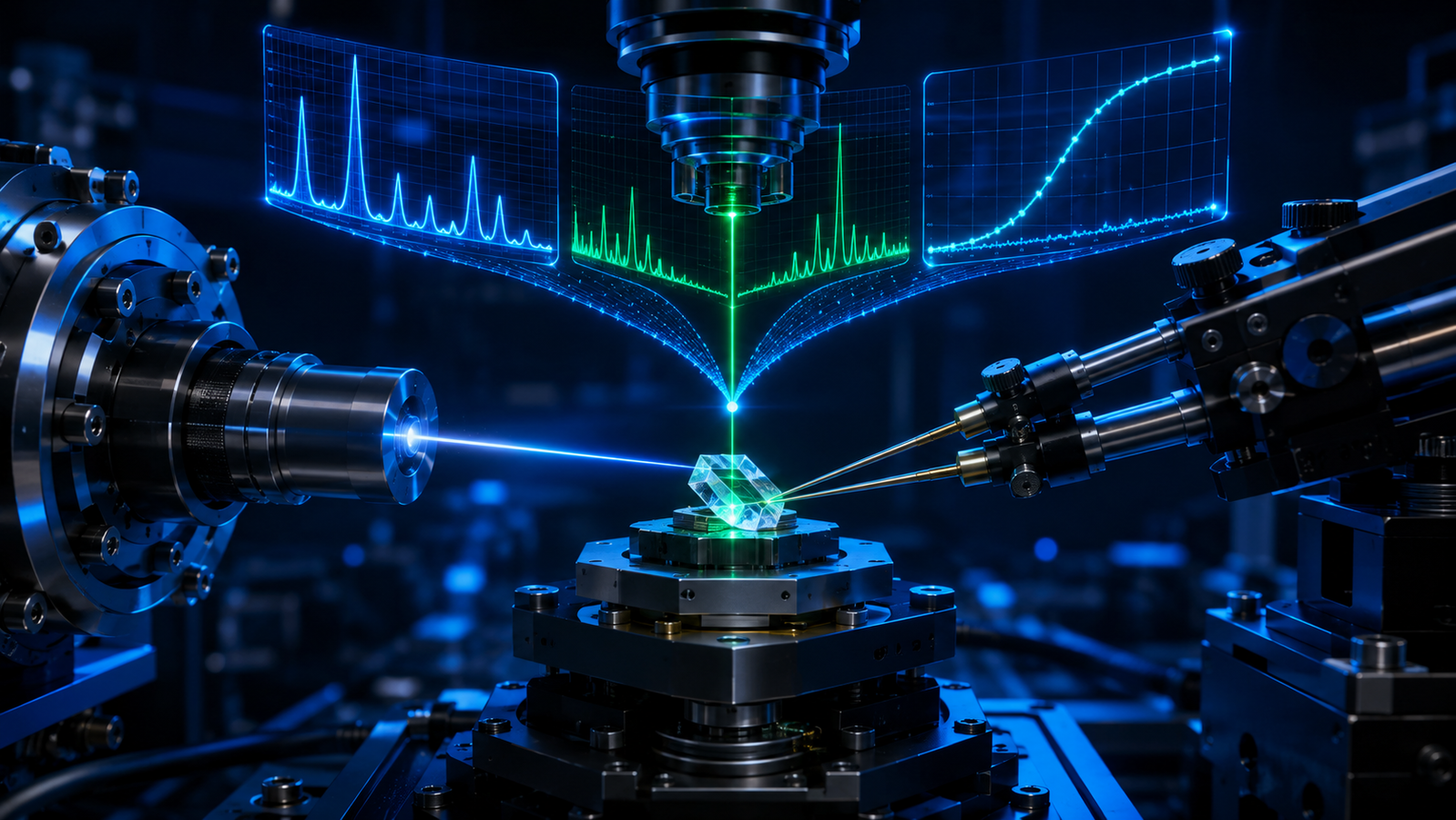
Every article in this knowledge hub has taught one instrument to watch one thing happen: a microscope watching oxidation, a diffractometer watching lattices, four probes watching carriers. This closing chapter is about what happens when the training wheels come off — when the sample is not merely held at temperature but made to work (a battery cycling, a catalyst converting, a film growing) while it is measured, and when one probe rarely determines the full mechanism and several interrogate the same sample at once. The first move has a name, operando; the second, correlative. Together they are where in-situ characterization is heading, and this article maps the territory: the definitions that keep the literature honest, why single probes systematically underdetermine complex mechanisms, how multiple channels triangulate an event, and the unglamorous alignment work that makes a multi-instrument story true rather than merely simultaneous.
1. From In-Situ to Operando: Climbing the Ladder
The distinction is worth being pedantic about, because the literature increasingly is. Ex-situ: take the sample out, measure it cold — and hope nothing relaxed, oxidized or transformed on the way. In-situ: measure inside the controlled environment, which is what every stage in this hub exists for. Operando: measure while the system performs its function, with the performance metrics (current, conversion, capacity) recorded in the same time base as the structural probe — so that when the diffraction pattern changes, you know what the device was doing at that instant, not merely how hot it was. The idea is older than the word: dynamic X-ray diffraction of a battery electrode during electrochemical cycling was demonstrated in 19781, and the modern methodological landscape — cells, beams, detectors and the discipline of simultaneous performance recording — is mapped in the current operando X-ray reviews2. The ladder’s payoff is inferential strength: correlations between structure and function measured on the same clock sharply narrow the plausible mechanistic sequence in a way that separately assembled experiments cannot — though simultaneity alone still does not prove causality, which takes controls, perturbation tests and reproducibility on top.
2. Why Single Probes Underdetermine the Mechanism
Every probe in this hub is honest about some things and structurally blind to others. Diffraction reports the crystalline, long-range-ordered fraction, averaged over the illuminated volume — amorphous products, surface layers and minority phases below its detection floor simply do not appear. Raman reports local bonds in a micrometer spot — exquisitely sensitive to what happens under the laser, silent about the other 99.99% of the sample, and capable of perturbing what it measures through laser heating. Electrical transport integrates the entire current path into one number — supremely sensitive to that something changed, incapable of saying what or where. Imaging sees morphology at the surface and projects everything beneath. None of these is a flaw; each is a definition. The failure mode is treating any single channel’s silence as the sample’s silence — a transition that is invisible to one probe (a surface reconstruction under diffraction; a homogeneous lattice shift under imaging) is often loud in another. The correlative argument is exactly the surveyor’s: one bearing gives a line, two give a point, three give a point with an error estimate. The channels are complementary rather than independent — they share the sample, the temperature program, often a window and a clock — which is precisely why their agreements and disagreements are both informative.
| Probe | Sampled volume | Strongest information | Main blind spot | Main perturbation risk |
|---|---|---|---|---|
| XRD | Beam-averaged | Crystal structure, phase | Amorphous / low-fraction surface states | Beam effects, cell background |
| Raman | Local optical spot | Bonds, local phase, stress | Representativeness of one spot | Laser heating |
| Electrical | Full current path | Functional transport | Cannot localize the cause | Joule heating, contacts |
| Optical imaging | Surface field of view | Morphology, coverage | Limited structural identity | Illumination, focus drift |
| SEM | Surface / near-surface | Fine morphology | Vacuum compatibility, little bulk information | Beam effects |
3. The Correlative Toolbox: The Stage as Common Denominator
What makes correlative work practical rather than heroic is that the stimulus platform is shared. A temperature-controlled stage with the right windows and feedthroughs is the common denominator: the same sample environment serves an optical microscope one week and a Raman spectrometer the next — or, with beam access and electrical feedthroughs, several at once. The hub’s own articles are the toolbox’s chapters: in-situ XRD for lattice and phase, variable-temperature Raman for bonds and stress, the electrical probe family for transport, SEM stages for morphology in the electron microscope. Two design features decide whether a stage graduates from single-probe to correlative service: optical and beam access (window material, aperture and geometry compatible with more than one instrument) and synchronizable control — where supported by the controller, software, API or external-trigger configuration, a temperature program that can be commanded, logged and time-stamped so that two instruments’ datasets can later be laid on one axis; available interfaces and synchronization behaviour are model- and configuration-specific and should be confirmed at quotation. Purpose-built multi-environment sample cells for beamline work show how far the same logic scales3.
4. Interactive: The Multi-Probe Event Lab
The simulator below stages Section 2’s argument. One sample warms through a hidden transition; three channels watch — a diffraction peak position, a Raman shift, and an electrical resistance — each with its own baseline drift and noise. Slide the temperature and watch each channel’s anomaly detector hesitate on its own, then watch the joint verdict fire when the witnesses agree.
The lesson is the surveyor’s, made visible. Any single channel’s deviation could be drift, noise or an artifact — each detector alone stays at “possible.” Three complementary channels — each carrying independently generated measurement noise — deviating at the same temperature is a different epistemic object: the joint verdict fires, and the transition temperature comes with a cross-checked confidence no single instrument could supply. The model is schematic — three illustrative response curves sharing one transition temperature, with independent noise — and real correlative work adds the alignment homework of Section 7: instruments that disagree about when can manufacture or destroy exactly this kind of coincidence.
5. The Time-Resolution Ladder
Operando work lives or dies by whether the probe is faster than the process. Laboratory diffraction historically metered minutes per pattern; the time-resolved in-situ tradition pushed powder diffraction into genuinely kinetic territory4, and synchrotron sources with modern area detectors now deliver patterns at seconds and below — fast enough to watch mechanochemical reactions mid-milling5 and energy materials operating far from equilibrium6. Laboratory instruments have climbed the same ladder more modestly: purpose-built transmission geometries bring in-situ and operando capability to the home lab at its own cadence7. Two disciplines keep the ladder honest. First, match cadence to kinetics — a five-minute pattern of a thirty-second event is an average, not an observation. Second, treat the resulting time series as one object: parametric refinement, which fits a physical model across the whole sequence rather than pattern-by-pattern, is the analysis-side twin of fast acquisition8.
6. Case Gallery: What the Combined View Buys
Batteries are the flagship: operando diffraction watches electrode lattices breathe with state of charge while the potentiostat writes the performance track — graphite’s staged lithiation being the canonical readout9 — and the story is rich enough that it has its own companion article in this hub. Gas–solid systems show the multi-stimulus face: crystallographic studies of gas sorption in metal–organic frameworks track the host lattice responding to pressure and temperature together, structure and uptake on one clock10. Thin-film growth and processing put synthesis itself under the beam, watching phases appear and compete during deposition and annealing rather than autopsying the result7. And correlative mechanics closes the loop with this hub’s tensile wing: full-field optical strain mapping during a pull ties the load cell’s global number to where the strain actually went11 — imaging and mechanics as two channels of one experiment. The common thread: in every case the mechanistic assignment (“this structural event accompanies — and plausibly drives — that functional change”) becomes testable only because two records share a clock; establishing it as causal still takes the controls and perturbations above.
7. The Alignment Problem: One Sample, One Clock, One Temperature
The quiet failure mode of multi-instrument work is misalignment — three kinds. Time: two instruments’ timestamps drift or offset, and a genuine cause-effect sequence flips order in the merged dataset; synchronization (shared triggers, logged clocks, deliberate fiducial events) is experiment design, not bookkeeping. Temperature: each instrument’s sample sits in its own thermal reality — different stages, different lags, different sensor offsets — so “both at 350 °C” is a claim about two calibration chains12, and the lag physics every stage article in this hub develops means ramping instruments disagree even when their setpoints agree. Space: probes with different spot sizes and depths sample different material; a Raman microspot and a millimeter X-ray beam can honestly disagree about a heterogeneous sample because they are measuring different places. The alignment audit — whose clock, whose thermometer, whose volume — belongs in the methods section of every correlative claim.
8. The Error Budget: Multi-Probe Edition
Everything from the single-probe articles carries over; correlative work adds the interaction terms. Probe–probe interference: the Raman laser is a local heater — capable of shifting the very transition the diffraction channel is timing — and beam heating plays the same trick from the X-ray side; the small-volume self-heating logic generalizes to every energy-depositing probe13. Window compromises: a window transparent and flat enough for optics, transmissive enough for X-rays and inert to the atmosphere is a real constraint set, and each probe pays a different price for the shared solution. Cadence mismatch: channels sampled at different rates create false lead-lag structure unless resampled honestly. And the alignment terms of Section 7, which are systematic and silent — the review literature’s consistent counsel is to engineer the synchronization and validate the sample environment before believing any cross-channel causality2.
9. Getting Started: A Realistic On-Ramp
The good news is that the on-ramp is incremental. Start with one stage and two probes in sequence: the same sample, the same logged temperature program, optical microscopy this week and Raman next — correlative in sample and program if not yet in simultaneity. Graduate to true simultaneity where the geometry allows: transparent-window stages already serve optics and spectroscopy at once; electrical feedthroughs add transport as a third channel on the same platform. The hardware requirement is the pair of features from Section 3 — multi-instrument access and loggable, synchronizable control — and the InSitu Pro™ stage family includes platforms and access geometries that can be configured for such workflows, from optical and electrical stages to diffraction and SEM platforms — available logging, API, trigger and synchronization interfaces remain model- and configuration-specific; the stage selector will match access geometry to your instrument pair, and multi-probe configurations are a quotation conversation. The cultural requirement is smaller but real: write the alignment audit into the plan on day one, because it cannot be retrofitted onto data.
10. FAQ: Operando & Correlative Work
11. Keep Exploring the InSitu Pro™ Knowledge Hub
This article is the trend-line of the InSitu Pro™ knowledge hub — the direction all the single-probe chapters point. To keep going:
- In-situ heating, cooling & electrical stages: a theory guide — the pillar article every probe chapter builds on.
- In-situ XRD: watching crystal structure evolve — the diffraction channel in depth.
- Variable-temperature Raman spectroscopy — the vibrational channel in depth.
- In-situ electrical probe stages — the transport channel in depth.
- Battery research in-situ: XRD, Raman & electrochemistry — the flagship operando application, three channels on one cell.
- How to choose an in-situ heating & cooling stage — the five-step selection guide.
References
This article discusses operando and correlative measurement methodology in general terms. Definitions, capability descriptions, time resolutions and alignment practices are idealized and instrument-, facility- and sample-dependent; real experimental design should be validated against the published literature, facility documentation, your own calibrations and the manufacturers’ datasheets before quantitative use. The interactive simulator is a schematic teaching tool — three illustrative response channels sharing a stated model transition, not measured data for any real material or instrument combination. Multi-probe and operando stage configurations are experiment-specific; contact ACS Material to discuss access geometry, feedthroughs and synchronization options for your application.