
Slow evaporation, missed pressure targets, foam carry-over and solvent reaching the pump call for different checks. This rotary evaporator troubleshooting guide works symptom by symptom, from possible cause to check order. Its static pressure-rise example calculates apparent gas accumulation, not automatically an external leak rate. Condensate in a downstream trap may be expected capture rather than a fault.
Quick answer: Stop safely for damaged glass, escalating foam, suspected pump contamination or a protective trip. Otherwise compare one observation at a time with a documented successful run. For slow evaporation check composition, fill, measured pressure, bath and cooling. For poor vacuum, an approved dry-system check helps separate load-related behavior from pump, connection or measurement problems; it does not prove the cause. A pressure-rise result does not by itself identify external leakage. Review foam and trapping under the approved method, not by automatically adding heat or deeper vacuum.
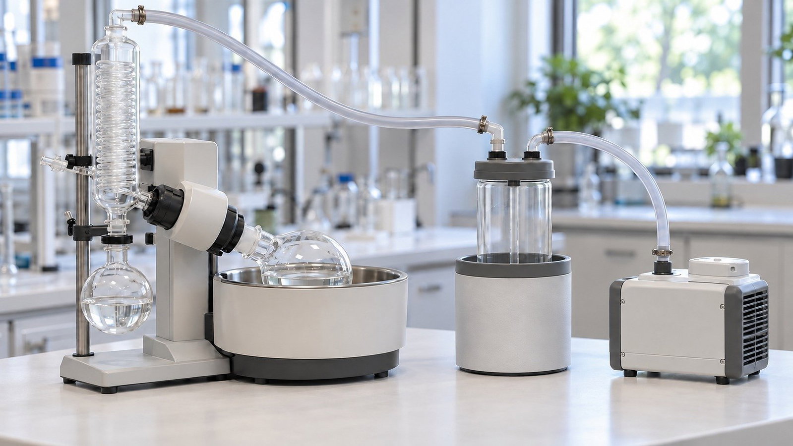
1. Start Here: Symptom, Cause, First Check
Symptoms covered in this guide
For the symptom "Vacuum will not reach setpoint," the complete guide to rotary evaporation lists these first checks: "Seal condition; joint seating; tubing and clamps; trap lid; whether solvent vapor load is simply exceeding pump capacity." The table below extends that approach to the five symptoms this article covers. Read across the row, then go to the section.
| Symptom | Possible causes | Check first | Section |
|---|---|---|---|
| Evaporation slower than usual | Changed composition or fill; heat-transfer or cooling limitation; unexpected pressure | Composition, fill, measured temperatures, coolant flow and actual pressure | 2 |
| Rotovap not reaching vacuum | Gas load, leaks, restrictions, pump condition, valve configuration or measurement error | Approved dry-system baseline, gauge and valve state; then pump and connections | 3 |
| Pressure rises after isolation | Leakage, outgassing, residual evaporation, isolation error or thermal drift | Stabilized pressure-rise record with known isolated volume; repeat under matched conditions | 4 |
| Foam climbing the vapor duct | Sample-dependent foam stability; unsuitable fill, rotation, heating or pressure changes | Stop safely if carry-over threatens; review charge, settings and method | 5 |
| Unexpected trap accumulation or solvent reaching pump/exhaust | Incomplete condensation, receiver re-evaporation or liquid carry-over | Cooling and circulation, rate, drainage, receiver and existing trap | 6 |
Change one variable at a time
How a rotary evaporator works recommends changing one variable at a time. Compare composition, charge, settings and measured conditions with a successful run [5][6]. This discipline is for controlled troubleshooting, not a reason to continue an unsafe run. Stop and follow the approved shutdown procedure when glass damage, exposure or uncontrolled carry-over is suspected.
2. Slow Evaporation
Check the inputs before the hardware
First verify the sample identity, composition and intended phase. The teaching troubleshooting text raises the possibility of an aqueous layer being mistaken for the intended organic phase [2]; check the preparation record rather than inferring identity from slow evaporation. Elapsed time alone does not establish a fault or justify more heat.
Compare measured pressure and temperatures with the approved method and sample limits. The solvent boiling points under vacuum article and the RE100-S/Pro product descriptions use the Δ20 °C rule. Treat it as an illustration, not a universal operating requirement or evidence of adequate cooling. Pure-solvent saturation estimates do not determine mixture behavior, flask temperature or evaporation rate [11][13].
A run that slows part way through
Composition, concentration, film behavior, pressure and cooling can change during a run. A slowdown alone does not establish which changed or justify progressively deeper vacuum. Compare the observations with the method; several components may evaporate together. Unusual downstream accumulation or loss of condensation warrants the checks in section 6, not an assumed pressure program.
Film, fill and rotation
The article on why the flask rotates explains why film behavior and over-filling matter. Teaching procedures use a no-more-than-half-full guideline [1][4], not a model-specific working-charge rating. Confirm the permitted charge, flask compatibility and method before splitting a batch or selecting another flask. Do not respond to a slow run automatically with more heat; the film mechanism is covered in that article.
Condenser, coolant and the specified rate
Check condenser cleanliness and the measured coolant inlet/outlet temperatures and circulation. Deposits can reduce heat transfer [11]. Establish the method's required cooling conditions before evaporation; a running chiller or a low setpoint alone does not establish delivered flow or sufficient cooling.
The RE100-S and RE100-Pro are specified at a maximum of 1.56 L/h with water. That is a maximum stated for water under the manufacturer's conditions, not a troubleshooting pass mark for another method. A change from a documented comparable run warrants investigation; it does not by itself identify an equipment fault.
3. Rotovap Not Reaching Vacuum: The Check Order
First, compare with a dry-system baseline
A missed pressure target during a run does not by itself identify an equipment fault. The C410 diaphragm pump has a 13 mbar ultimate-vacuum rating, which is not a pressure it will hold during evaporation; actual operating pressure depends on vapor load, condenser performance, tubing conductance, system tightness and solvent compatibility. An ultimate-pressure test uses specified blank-off conditions without imposed process throughput; residual gas sources remain. It is not a loaded operating-pressure guarantee [7][10].
After safe shutdown, use the instrument's approved dry, empty-system check. Compare readings under matched valve, rotation, temperature and gauge conditions. Recovery of the baseline suggests a load-related contribution but does not exclude leaks that appear only during operation. Failure to recover it also warrants checks of restrictions, valves, gauge behavior and pump condition, not leaks alone.
The check order
Use the following as a diagnostic sequence, not a servicing procedure. Vent, cool, decontaminate as needed and isolate power before touching joints or seals. Pressure checks require the approved test setup. Do not import another instrument's instructions to grease joints, bend tubing or replace seals [3][14].
| Step | What to check | How |
|---|---|---|
| 1 | Pump and pressure measurement | Use the authorized blank-off test and suitable gauge; compare with a documented baseline. An open inlet is not a blank-off test; internal service is outside this guide. |
| 2 | Hoses and clamps | Inspect accessible tubing for damage, collapse or loose connections after safe shutdown. |
| 3 | Vent valve and stopcock | Check the instructed test position; a hiss alone does not identify a leak. |
| 4 | Joints and clips | With the system vented and cool, inspect seating, contamination and chips; do not adjust evacuated glassware. |
| 5 | Receiver, trap and glassware | Inspect accessible seating, trap lid, residue and cracks under the operating instructions. |
| 6 | Rotary vacuum seal | Inspect only as authorized for damage, deposits or deformation; escalate inaccessible seals or uncertain findings. |
For step 2, ACS Material advises using vacuum tubing rated for the solvents in use with the C410, and keeping runs short and bores wide. For step 5, the complete guide says: "Check glassware, seals, clips and the flask for star cracks, scoring or hardened seals. A leaking seal can invalidate the system's performance specifications." Never put a cracked flask under vacuum [4][14].
For sectional testing, use only approved isolation points and determine each isolated volume. Compare Q under comparable starting pressure, temperature and test conditions, not raw mbar/min across different volumes. Changed boundaries, connecting fittings and isolation leakage can alter the result; a larger rise alone does not locate a defect.
Inspecting seals and joints
This article covers seal and joint inspection only; it specifies no replacement part. With the system safely vented, cool and isolated, inspect authorized accessible sealing faces for damage, deposits or deformation. Compatibility depends on the actual solvent, material and exposure conditions; a local teaching-lab warning about gasket degradation is not a universal material-life rule [4]. Follow the instrument instructions for cleaning or service, and do not disassemble inaccessible seals on this guide's authority.
4. Rotovap Leak Test: A Worked Pressure-Rise Example
Test setup and assumptions
A pressure-rise test measures pressure change in an isolated volume [8][9]. Leaks, outgassing, residual evaporation and temperature drift can contribute, so the result alone does not identify a leak. Keep the pressure sensor on the isolated-system side. The VC100 vacuum controller has a specified 1–1000 mbar measurement range, but that range alone does not establish resolution, accuracy or suitability for these small changes. Confirm the gauge and a measurement-only configuration that does not admit or remove gas during the test.
- Use an approved test configuration: empty, clean and dry, with intact vacuum-rated components. Document rotation and coolant conditions; do not improvise changes on evacuated equipment.
- Establish a permitted test pressure and allow pressure and temperature to stabilize. The 50 mbar absolute starting value below is selected for arithmetic, not an ALab test specification.
- Isolate through the designated device on the pump side of the sensor; do not assume bending a hose gives reliable isolation.
- Record pressure, temperature and elapsed time at several points. The example uses 60 s, not a prescribed test duration.
- Re-pump under the same conditions and repeat. Follow the approved shutdown procedure before opening or adjusting the assembly.
A repeatable, nearly linear rise can be consistent with leakage, while a smaller rise after further pumping can suggest outgassing. Neither pattern proves the cause; outgassing itself is measured by pressure-rise methods [7][8][19]. Temperature change, permeation, trapped gas and imperfect isolation can affect the trace. A short, straight segment is not an external-leak diagnosis.
The calculation: Q = V · Δp / Δt
For fixed, known isolated gas volume V and approximately uniform, constant gas temperature, Q = V·dp/dt describes net gas accumulation in pressure-volume units [7][9]. Over a measurement interval:
Q = V · Δp / Δt, in mbar·L/s, with V in L, Δp in mbar and Δt in seconds.
Call this an apparent gas load unless external leakage has been distinguished from other sources and sinks. Gauge drift, temperature change or an uncertain volume can invalidate the simple interpretation; active pumping or condensation may also mask incoming gas.
Assume an isolated free gas volume of 3.0 L for illustration. The RE100-S and RE100-Pro package lists each include 1000 mL evaporating and receiving flasks, but those nominal capacities plus an assumed 1 L elsewhere do not measure the connected gas volume. For an actual test, determine the volume inside the isolation boundary, including connected passages and the sensor; document uncertainty. Case B uses a separate assumed 6.0 L volume.
| Case | V (assumed) | Absolute pressure: start → after 60 s | Δp/Δt | Q = V·Δp/Δt | Equivalent volume flow at 1013 mbar |
|---|---|---|---|---|---|
| A: lower rise | 3.0 L | 50.0 → 52.0 mbar | 2.0 mbar/min = 0.033 mbar/s | 0.10 mbar·L/s | ≈ 6 mL/min |
| B: same rise, larger system | 6.0 L | 50.0 → 52.0 mbar | 2.0 mbar/min | 0.20 mbar·L/s | ≈ 12 mL/min |
| C: higher rise | 3.0 L | 50.0 → 58.0 mbar | 8.0 mbar/min = 0.133 mbar/s | 0.40 mbar·L/s | ≈ 24 mL/min |
The last column is Q divided by 1013 mbar, converted to mL/min, assuming ideal-gas behavior and the same gas temperature at both reference conditions. For A, 0.10/1013 L/s gives 5.9 mL/min, rounded to 6. This is an equivalent volume flow, not a measured air leak or standard-temperature flow. B shows that equal pressure-rise rates in twice the volume imply twice the apparent gas load; C shows a larger load, not an identified leak path.
Reading the result against an experience value
No pressure-rise acceptance limit is specified for the four ALab products. EN 13184 describes pressure-change testing [9]; citing it here does not establish a rotary-evaporator pass mark. A University of Cape Town chemistry SOP gives less than 3 mbar/min in its instrument-specific vacuum-tightness test [3]. That passage describes a rotating flask and pump isolation but specifies no initial pressure or internal gas volume.
Retain the SOP figure only as a source-specific experience value. At the assumed 3 L, 3 mbar/min corresponds arithmetically to 0.15 mbar·L/s. Cases A/B fall below and C above that pressure-rise figure, but none receives an ALab pass/fail verdict. Establish acceptance criteria for the actual equipment and method; compare documented baselines under matched conditions, not as proof of safety.
5. Foaming in a Rotary Evaporator
Foaming and bumping differ
Foaming and bumping are different phenomena and may occur together. Foam stability depends on the sample; a persistent foam layer or a sudden surge is not a definitive diagnostic test. The thin films and bumping article covers the mechanism. Here the priority is avoiding carry-over and reviewing the operating conditions.
What to review
The linked flask-rotation article notes that high speed may worsen foaming in some samples. Within an approved method, review these factors one at a time:
- Rotation: a lower speed may help some samples but also changes film behavior; there is no universal setting.
- Charge and headspace: confirm permissible fill and flask compatibility; the half-full teaching guideline is not a manufacturer charge rating [1].
- Heating: review the bath-to-sample temperature difference within sample and equipment limits rather than adding heat.
- Pressure approach: avoid unreviewed abrupt changes; no pressure program is prescribed here.
- Chemistry: consider solvent changes or antifoam only after compatibility, product-recovery and downstream-analysis assessment [12].
If foam approaches the vapor path, follow the approved shutdown or recovery procedure. Do not improvise venting or detach evacuated or hot glassware. Reassess the method before restarting.
After foam carry-over
Where a bump trap is already fitted, inspect it and the downstream path after safe shutdown; it does not guarantee containment. Carry-over may contaminate the condenser and receiver. Assess all affected components and follow the approved cleaning procedure before reuse. The cited university rules warn that dried residue can bind joints [4]; do not force stuck glassware.
6. Solvent in the Vacuum Pump
Observations to investigate
A downstream cold trap is intended to collect condensable material; some accumulation is not itself a fault. The complete guide treats substantial or increasing accumulation as a reason to check primary condensation. Solvent reaching the pump may involve uncondensed vapor, receiver re-evaporation or liquid carry-over. Lost vacuum or low recovery is nonspecific. Suspected exhaust emissions require the laboratory's exposure response, not deliberate smelling or continued operation.
Causes and checks
- Cooling not established. Check actual temperatures, circulation and the required heat duty before starting; local warm-up timings in a teaching procedure are not universal chiller specifications [4].
- Vapor load or carry-over exceeds the installed system's capability. Check rate, drainage, fill and condenser condition. RE100-S lists 1200 cm² (1700 cm² available for selection); RE100-Pro lists 1700 cm². Area alone does not establish condensing capacity [11].
- Solvent retained in the receiver. Review re-evaporation and collection handling; empty only after the approved shutdown and venting sequence, not while evacuated [4].
- Existing trap condition. Check the approved trap temperature, accumulated material, capacity and flow path. A temperature label alone does not establish capture for the intended vapor.
Trapping and exhaust controls
For the C410, ACS Material advises appropriate upstream cold or moisture trapping when condensable vapor load is high and routing solvent-laden exhaust according to laboratory procedures. This is not a guarantee of capture or a statement that every moisture trap removes organic vapor. Confirm the approved configuration; this guide names no trap product or replacement accessory.
The C410's oil-free diaphragm operation differs from that of oil-sealed pumps, and solvent vapor can leave through its exhaust. Oil-free operation does not make vapor harmless or prove solvent compatibility. The VC100 is specified with PTFE, PP, silicone and ceramics in contact with vapor; its general corrosion-resistance statement is not a compatibility chart for every chemical, temperature and exposure. It describes the controller, not the pump, tubing or the complete system. Confirm the actual wetted materials and conditions.
Route solvent-laden exhaust through the ventilation arrangement approved for the process [14][16][17][20]. Trapping is not a substitute for exposure controls; never obstruct the exhaust or continue a suspected release while experimenting with settings.
7. Record a Baseline and Know When to Stop
Record the dry-system pressure under documented conditions, the complete pressure-rise trace and assumed or determined volume, and the measured rate of a defined routine method. Preserve gauge, temperature, rotation, isolation and timing details so later comparisons are meaningful. After a configuration change, repeat the authorized checks rather than carrying over an old result. Stop safely for damaged glass, uncontrolled carry-over, suspected pump contamination, exposure or an unresolved fault. The RE100-S/Pro have 220 °C overheating protection and boil-dry protection; these are not safe process temperatures or reset instructions. Investigate a trip and follow the operating or service instructions before restarting; do not bypass protection [14][15][16][18].
8. Frequently Asked Questions
How do I troubleshoot a rotary evaporator?
Start from the symptom and a documented comparable run. Check composition, charge, measured pressure and cooling before changing settings. For poor vacuum, use an approved dry-system test and inspect connections only after safe shutdown. Foam carry-over, damaged glass, protective trips or suspected pump contamination call for stopping safely and reassessment, not continued trial-and-error adjustment.
Why is my rotovap not reaching vacuum?
Possible contributors include vapor load, leaks, restrictions, valve settings, pump condition and measurement error. An approved dry-system check against a documented baseline helps narrow the search but does not prove the cause. Check the gauge and authorized pump test before inspecting accessible connections and seals after safe shutdown.
How do I do a rotovap leak test?
Use an approved, stabilized, dry-system test with a suitable sensor on the isolated side. Record pressure and temperature, then repeat under matched conditions. Q = V·Δp/Δt estimates apparent gas accumulation at constant volume and temperature; it does not by itself identify external leakage. The cited university SOP's less-than-3 mbar/min experience value is not an ALab acceptance limit.
What stops foaming in a rotary evaporator?
No single setting stops all foaming. Review charge and headspace, rotation, heating and pressure approach under the approved method. Chemistry changes require compatibility and product-impact assessment. Stop safely if carry-over threatens, and inspect any existing trap and affected components before reuse.
Why is there solvent in my vacuum pump?
Possible causes include incomplete condensation, receiver re-evaporation and liquid carry-over. Check cooling and circulation, evaporation conditions, drainage and the existing trap under the approved procedure. Trap capture does not guarantee that nothing reaches the pump; suspected pump contamination or exhaust release calls for safe shutdown and assessment.
9. Keep Exploring
- Rotary evaporation: the complete guide: principles, setup, maintenance and recovery.
- How a rotary evaporator works in five steps
- Solvent boiling points under vacuum: the Δ20 °C illustration.
- Why the flask rotates: thin films and bumping
- Rotary evaporation vs simple distillation
Equipment: RE100-S, RE100-Pro, VC100 vacuum controller, C410 diaphragm pump, and all rotary evaporators.