
Dip coating is one of the simplest ways to put a liquid film on a substrate: lower it into a bath, then pull it out at a steady speed. The withdrawal speed, the liquid’s viscosity and surface tension, and the rate at which solvent evaporates decide how much liquid stays on the surface and how thick the dry film becomes. This guide explains the stages of dip coating, the two main coating regimes and the standard equations behind them. It also shows how to run a withdrawal-speed series and which instrument specifications matter.
In one paragraph: the film thickness in dip coating is set mainly by the withdrawal speed, and the direction of the effect depends on the regime. At moderate speeds the Landau–Levich equation predicts that the wet thickness grows with speed to the power 2/3. At very slow speeds, solvent evaporation at the meniscus deposits material directly, and the thickness grows as speed falls. Between them is a speed of minimum thickness. For an entrained wet layer that dries to a dense film, multiplying wet thickness by the non-volatile volume fraction gives a first dry-thickness estimate. Because the regime boundaries depend on your liquid and atmosphere, a short series of measured speeds is the most reliable way to set a recipe.
1. The short answer
If you only need the essentials of dip coating, these five points cover most practical decisions:
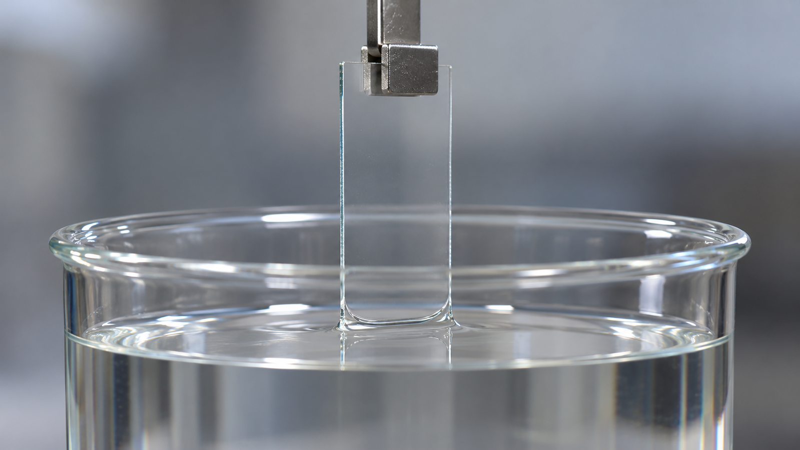
- Thickness is set at the meniscus. Where the substrate leaves the bath, viscous drag pulls liquid upward while surface tension and gravity pull it back. The balance decides how much liquid is carried away.
- Speed is the main control, but its effect changes direction. At moderate speeds, faster withdrawal gives a thicker film. At very slow speeds with a volatile solvent, slower withdrawal gives a thicker film.
- The Landau–Levich equation describes the draining regime. It predicts wet thickness from viscosity, surface tension, density and speed, for a Newtonian liquid and a slowly withdrawn vertical plate.
- For an entrained wet layer, dry thickness depends on solid content. Drainage, porosity and heat treatment also affect the final thickness.
- Measure, then model. A few speeds spread over a wide range, each with a measured thickness, show which regime you are in and give a working curve for your own liquid.
If you are still deciding whether dip coating is the right method, the pillar guide to solution-processed thin films compares spin, dip, slot-die and blade coating and includes an interactive coating method selector.
2. The five stages of dip coating
Scriven divided batch dip coating into five stages [1]. In continuous processes, several of them happen at the same time:
- Immersion. The substrate is lowered into the bath at a constant speed.
- Start-up. The substrate has dwelled in the bath and begins to move upward. The meniscus and the entrained film take a short time to reach a steady shape.
- Deposition. A thin layer is entrained on the moving substrate. The liquid splits at a stagnation point: liquid closer to the surface moves up with the substrate, while liquid further out returns to the bath.
- Drainage. Liquid in the entrained layer flows back down under gravity, so the film keeps thinning after it leaves the meniscus.
- Evaporation. Solvent leaves the film, concentrating the non-volatile material until it gels or solidifies.
With volatile solvents, evaporation overlaps with deposition and drainage. In sol-gel films this produces a wedge-shaped drying zone above the bath, in which the sol concentrates, gels and dries within a short distance [2]. Dwell time in the bath, which many dip coaters program as an immersion time, does not appear in the simple thickness equations. It can still matter where the substrate must wet fully, where species adsorb from the bath, or where a layer-by-layer process depends on adsorption.
3. Withdrawal speed: the main control
Withdrawal speed (often written U, U0 or u) is the variable you change most easily, and it has the largest effect on thickness. Dip coaters usually state it in millimetres per minute, while the equations need metres per second:
100 mm/min ≈ 1.667 × 10⁻³ m/s; 600 mm/min = 0.01 m/s; 0.1 mm/min ≈ 1.667 × 10⁻⁶ m/s
A common surprise is that the same change in speed can thicken one film and thin another. The literature describes three regimes [3][4]:
| Regime | Typical speed | What sets thickness | Speed dependence |
|---|---|---|---|
| Capillary (evaporation) | Very slow, volatile solvent | Evaporation at the meniscus feeds material onto the substrate | h ∝ U−1: slower is thicker |
| Intermediate | Around the minimum | Both mechanisms contribute | A minimum thickness at a crossover speed |
| Draining (Landau–Levich) | Moderate, low capillary number | Viscous drag balanced by capillary pressure and gravity | h ∝ U2/3: faster is thicker |
At higher speeds or viscosities, the viscous-gravity form h ∝ U1/2 takes over from the Landau–Levich law (Section 4). Where the regime boundaries fall depends on the liquid, the solvent and the atmosphere; they are not fixed speeds.
4. The draining regime and the Landau–Levich equation
For a Newtonian liquid and a vertical plate withdrawn slowly, Landau and Levich [5], and independently Derjaguin [6], derived the entrained wet film thickness by matching the thin film to the static meniscus. Brinker and co-workers wrote it in the form used for sol-gel dip coating [2]:
h = entrained wet film thickness (m); η = dynamic viscosity (Pa·s); U = withdrawal speed (m/s); γ = liquid–vapour surface tension (N/m); ρ = liquid density (kg/m3); g = 9.81 m/s2
The same result is often written using the capillary number and capillary length [7]:
Ca = capillary number (viscous force relative to surface tension); lc = capillary length, typically about 1.5–3 mm for common liquids
The prefactor is often quoted as 0.946. The difference is below 1% and smaller than the uncertainty in most measured liquid properties.
Illustrative example. Take an ethanol-like liquid with η = 1.2 mPa·s, γ = 0.022 N/m and ρ = 790 kg/m3, withdrawn at 100 mm/min (1.667 × 10⁻³ m/s):
- Ca = (1.2 × 10−3 × 1.667 × 10−3) / 0.022 ≈ 9.1 × 10⁻⁵, well below 1
- lc = (0.022 / (790 × 9.81))1/2 ≈ 1.68 mm
- h = 0.94 × 1.68 mm × (9.1 × 10−5)2/3 ≈ 3.2 µm of wet film on each face
Assumed liquid properties chosen to illustrate the calculation. They are not results from any coating liquid, dip coater or Levon™ instrument.
Because thickness scales with (ηU)2/3, doubling either the speed or the viscosity multiplies the wet thickness by 22/3 ≈ 1.59. Doubling the surface tension changes it by only 2−1/6 ≈ 0.89. In practice, speed and viscosity (through solid content and solvent) are the levers; surface tension is a weak one.
Limits. The derivation assumes a capillary number well below 1, a Newtonian liquid, steady withdrawal of a wide vertical plate, and no evaporation, surfactant or substrate roughness effects [8]. At higher capillary numbers, viscous drag is balanced mainly by gravity. The thickness then follows a viscous-gravity form, h = c1 · (ηU/ρg)1/2, with c1 of about 0.8 for Newtonian liquids [2]. Wilson extended the analysis with higher-order corrections that become important as the capillary number grows [9]. The companion article The Landau-Levich Equation in Practice: Viscosity, Surface Tension and Speed works through units, validity checks and fitting in detail.
5. The capillary regime and the thickness minimum
At very low withdrawal speeds with a volatile solvent, the picture changes. The meniscus moves so slowly that solvent evaporates from it faster than liquid is entrained. Evaporation draws solution toward the contact line, where solute is deposited directly on the substrate. Faustini and co-workers showed that in this capillary regime the deposited thickness increases as the speed decreases, scaling with the evaporation rate divided by the speed [3]. A related transition, from convective assembly at low speed to Landau–Levich deposition at higher speed, was reported for multilayered phospholipid films [10].
Combining the two contributions gives a semi-empirical description of dry thickness across the capillary-to-Landau–Levich crossover [3][4]:
A/U = capillary (evaporation) term: A depends on the evaporation rate per unit coating width and the solute content
B·U2/3 = draining (Landau–Levich) term: B collects viscosity, surface tension, density and solute content
Setting dh/dU = 0 gives the speed at which the film is thinnest:
A and B are fitted to measured thickness data for a given solution and atmosphere; they are not universal constants. Two practical consequences follow. First, a thickness can often be reached at two different speeds, one on each side of the minimum, and the films may differ in uniformity and structure. Second, anything that changes evaporation, such as temperature, airflow or solvent vapour above the bath, moves the capillary branch and the position of the minimum. The heated case is covered in Heated Dip Coating: How Temperature Shifts Evaporation and the Capillary Regime.
6. From wet film to dry film
The Landau–Levich equation gives the wet liquid layer. The dry film is thinner because the solvent leaves. For a solution that dries to a dense layer without lateral shrinkage, a first estimate is:
φ = volume fraction of non-volatile material in the coating liquid, counted as the dense dried solid (convert a weight-percent solid content using the solid and liquid densities)
Illustrative example. A 3.2 µm wet film of a liquid with φ = 0.05 gives hdry ≈ 0.05 × 3.2 µm ≈ 0.16 µm, or about 160 nm. The value of φ is assumed for the calculation.
Real films depart from this estimate in predictable directions. Porosity left after drying makes the film thicker than the dense estimate. Further condensation, densification or binder burn-out during heat treatment make it thinner. For sol-gel oxides, the structure and shrinkage of the gel on drying and firing are central to the final thickness and porosity [11][12]. In the capillary regime, solute deposits at the meniscus rather than from a draining wet film, so the wet-film estimate does not apply; the fitted A/U term is used instead [3]. The sol-gel case is covered in Sol-Gel Dip Coating: From Sol to Dense Oxide Film (SiO2, TiO2).
Repeating the dip builds thickness in steps. Each new layer is deposited on a different surface from the first, and a partly dried film can redissolve in the bath, so the thickness per cycle is not guaranteed to be constant. Many dip coaters program a number of cycles and an interval between them. Intermediate drying or heat treatment between dips is often used to stabilize each layer.
7. Drainage, film profile and edges
After the substrate leaves the meniscus, gravity keeps draining the liquid layer until the film gels or dries. For a vertical plate wetted by a Newtonian liquid that does not evaporate, Jeffreys gave the classic draining solution [13]:
x = distance down from the top of the draining film; t = draining time
The film is therefore thinner near the top and thicker lower down, and it keeps thinning until solidification stops the flow. With a volatile solvent the film usually solidifies quickly, which limits drainage. With a slowly drying solvent, drainage can produce a visible thickness gradient along the withdrawal direction. Several other features of dip-coated films follow from the geometry:
- Both faces are coated. If only one face is needed, the other must be masked or cleaned afterwards.
- The top edge carries the start-up transient, so the first few millimetres are often discarded.
- The bottom edge collects a bead of liquid as the substrate leaves the bath. Touching the lower edge, or a sacrificial strip below the useful area, to an absorbent material wicks away the excess. Slowing the last part of the withdrawal can also reduce the bead, but test it first: with a volatile solvent, a slower finish can move the film into the capillary regime and deposit extra material near the bottom.
- The side edges are affected by the meniscus wrapping around them, so the central region is usually the most uniform.
Speed fluctuations and vibration print directly into the film as horizontal bands, because thickness depends on instantaneous speed at the meniscus. A rigid stand, a smooth drive and a draught-free location all help.
8. Other variables that change thickness
| Variable | Effect in the draining regime | Practical note |
|---|---|---|
| Viscosity η | h ∝ η2/3 | Rises with solid content and aging of sols; strongly temperature dependent |
| Surface tension γ | h ∝ γ−1/6 | Weak effect on thickness, but strong effect on wetting and dewetting |
| Density ρ | h ∝ ρ−1/2 | Changes little for a given solvent |
| Solid content | Raises η and φ | Often the simplest way to change dry thickness at a fixed speed |
| Temperature | Lowers η and speeds evaporation | Can shift the regime boundaries as well as the thickness |
| Atmosphere and humidity | Change evaporation and, for sol-gel, hydrolysis | Covers or enclosures reduce draughts; humidity matters for many sols |
| Substrate surface | Wetting is assumed complete | Poor wetting causes dewetting and bare patches; cleaning comes first |
Non-Newtonian liquids, such as concentrated particle suspensions and some polymer solutions, do not follow the Landau–Levich exponent exactly, and surfactants can thicken the entrained film [8]. For such liquids, the measured speed–thickness curve is the reference rather than the formula.
9. How to run a withdrawal-speed series
A speed series takes only a few substrates and shows which regime your liquid is in:
- Fix everything except speed: solution batch, temperature, immersion time, atmosphere and drying step.
- Choose speeds spread on a logarithmic scale, for example 1, 3, 10, 30, 100 and 300 mm/min, so that both low-speed and draining behaviour can appear.
- Measure the dry thickness in the same central region of each film, by profilometry, ellipsometry or optical interference. A dedicated article, How to Measure Thin Film Thickness: Profilometry, Ellipsometry and Interference (coming soon), will cover these methods.
- Plot log h against log U. A slope near +2/3 indicates the draining regime; a slope near +1/2 at high speed indicates the viscous-gravity form; a slope near −1 at low speed indicates the capillary regime.
- Fit only the branch you will use, and interpolate rather than extrapolate. The same log–log fitting logic is worked through for spin coating in Spin Speed vs Film Thickness: How to Build and Use a Spin Curve.
Illustrative scaling. In the draining regime, each step of √10 ≈ 3.16 in speed multiplies the thickness by (√10)2/3 = 101/3 ≈ 2.15. In the capillary regime the same step divides the thickness by about 3.16. These are ideal exponents; real data scatter around them.
Time per stroke. The withdrawal time is the immersed length divided by the speed. Withdrawing 100 mm takes 10 s at 600 mm/min, 10 minutes at 10 mm/min and 1,000 minutes (about 16.7 hours) at 0.1 mm/min. Very slow runs therefore need a stable environment for hours, and their duration should be planned before a series is scheduled.
10. Dip coater specifications that matter
When comparing dip coaters, these specifications map directly onto the physics above:
- Speed range: the lowest speed decides whether you can reach the capillary regime; the highest decides how thick a draining-regime film can be.
- Stroke: the travel must exceed the coated length plus the start-up zone.
- Positioning accuracy and thrust: these describe the drive. Speed smoothness, which governs banding, is a separate property and is not always stated.
- Immersion time, interval and cycles: needed for multilayer films and adsorption-based processes.
- Substrate size, glovebox fit, heating and multi-beaker operation: these decide where and how the coater can be used.
The table compares the three Levon™ dip coater pages. Values are quoted from each page; “not stated” means the page does not give the value, not that the feature is absent.
| Specification | DP100-BE | DP100-BE-H | DP150-DR |
|---|---|---|---|
| Running speed | 0.1–600 mm/min | 0.1–600 mm/min | 0.1–600 mm/min |
| Stroke | 0–100 mm (other strokes can be customized) | 0–100 mm (other strokes can be customized) | Max. 240 mm |
| Displacement accuracy | ±0.01 mm | ±0.01 mm | ±0.1 mm |
| Rated linear thrust | >50 N | >50 N | >100 N |
| Immersion time | 1–9,999.9 s | 1–9,999.9 s | 0–9,999.9 s |
| Repeat coating interval | 1–9,999.9 s | 1–9,999.9 s | 0–9,999.9 s |
| Coating cycles | 1–999 | 1–999 | 1–999 |
| Max. substrate | ≤100 × 100 × 5 mm | ≤100 × 100 × 5 mm | ≤150 × 150 × 5 mm |
| Solution positions | Not stated | Not stated | Six-position turntable, six standard 300 mL beakers; turntable 0.1–10 rpm |
| Heating | Not stated | Heated base, RT to 120 °C, temperature controllable | Not stated |
| Glovebox | Compact structure designed for placement in a glovebox | Compact structure designed for placement in a glovebox | Not stated |
| Recipes | 100, named and stored | 100, named and stored | 100, named, stored and recalled |
| Dimensions (W × D × H) | 227 × 350 × 416 mm | 227 × 350 × 416 mm | 303 × 519 × 550 mm |
Specifications as published on the Levon™ product pages on 22 October 2026. The DP100-BE-H page states a heated base; it does not state the bath or substrate temperature reached. RT (room temperature) has no numeric value on the page and no cooling is stated. For glovebox use, check the antechamber size and internal height against the stated dimensions. The DP150-DR page lists the 150 × 150 × 5 mm substrate limit and the six standard 300 mL beakers as separate specifications; a typical 300 mL laboratory beaker is narrower than 100 mm, so confirm the bath container and immersion depth for large substrates.
All three share the same speed range, so the choice usually comes down to substrate size, stroke, glovebox use, heating and the need for several solutions. Multi-solution and layer-by-layer work with a turntable is covered in Layer-by-Layer and Multi-Solution Dip Coating with a Carousel Dip Coater. The full range is on the Levon™ dip coater category page.
11. Dip coating or spin coating?
Both are batch methods for laboratory films, but they suit different jobs [1]:
- Choose dip coating for coating both faces, non-flat or larger parts that fit the bath, slow and gentle film formation, very thin films from dilute solutions, and multilayers built from several baths.
- Choose spin coating for one-sided films on flat substrates, small liquid volumes, fast cycle times and thickness control through spin speed.
Dip coating needs a filled bath even for a single sample, but a stable bath can coat many samples, so the bath volume is not the amount of liquid used per run. Spin coating flings most of the dispensed liquid off the substrate. For the physics of spin coating, see Spin Coating Explained: Stages, Physics and Film Thickness; for a side-by-side choice among four methods, use the coating method selector in the pillar guide.
12. Keep Exploring the Dip Coating Knowledge Hub
Start here
- Solution-Processed Thin Films: Choosing Spin, Dip, Slot-Die or Blade Coating — when dip coating is the right method, with the interactive coating method selector.
- Spin Coating Explained: Stages, Physics and Film Thickness — the stages, thickness models and defects of the main alternative to dip coating.
Dip coating process guides
- The Landau-Levich Equation in Practice: Viscosity, Surface Tension and Speed — units, validity checks and worked examples.
- Sol-Gel Dip Coating: From Sol to Dense Oxide Film (SiO2, TiO2) — from sol preparation to dried and fired oxide films.
- Layer-by-Layer and Multi-Solution Dip Coating with a Carousel Dip Coater — sequential baths, rinses and cycles.
- Heated Dip Coating: How Temperature Shifts Evaporation and the Capillary Regime — temperature, evaporation and the thickness minimum.
- How to Measure Thin Film Thickness: Profilometry, Ellipsometry and Interference (coming soon) — checking your speed–thickness curve.
Levon™ dip coaters
- DP100-BE Dip Coater — 0.1–600 mm/min, 0–100 mm stroke, substrates to 100 × 100 mm, designed for placement in a glovebox.
- DP100-BE-H Heated Dip Coater — the same motion range with a heated base, RT to 120 °C.
- DP150-DR Carousel Dip Coater — six-position turntable for six standard 300 mL beakers, 240 mm maximum stroke, substrates to 150 × 150 mm (the bath container may set a smaller practical limit).
- All Levon™ dip coaters — the dip coater category page.
Questions about a specific substrate, solution or configuration can be sent through the contact form.
13. FAQ
What is dip coating?
Dip coating is a solution deposition method in which a substrate is immersed in a coating liquid and withdrawn at a controlled speed. A liquid film is entrained on both faces, then drains and dries to leave a solid film. Thickness is controlled mainly by withdrawal speed, liquid properties and evaporation.
Does a faster withdrawal speed make a thicker or thinner film?
In the draining regime, which covers most moderate speeds, faster withdrawal gives a thicker film, with wet thickness scaling with speed to the power 2/3. At very slow speeds with volatile solvents, the capillary regime applies and slower withdrawal gives a thicker film. A short speed series shows which case applies to your solution.
What is the Landau–Levich equation used for?
It predicts the wet film thickness entrained on a vertical plate withdrawn from a Newtonian liquid: h = 0.94·(ηU)2/3/(γ1/6(ρg)1/2). It holds for capillary numbers well below 1, steady withdrawal and negligible evaporation during deposition.
How do I estimate the dry film thickness?
For an entrained wet layer in the draining regime, multiply its thickness by the non-volatile volume fraction, assuming a dense layer without lateral shrinkage. Porosity makes the real film thicker; densification on heat treatment makes it thinner. Measured thickness should replace the estimate as soon as you have it.
Why does my dip-coated film have horizontal bands?
Because thickness depends on the instantaneous speed at the meniscus, any speed fluctuation or vibration during withdrawal prints into the film as bands. Draughts and uneven evaporation can do the same. Check the stand and drive for vibration, shield the bath from airflow and keep the withdrawal speed constant.