Layer-by-layer dip coating builds a film through successive adsorption steps, by dipping a substrate in turn into solutions of oppositely charged (or otherwise complementary) species, with rinses in between. Unlike ordinary dip coating, where withdrawal speed sets the thickness, layer-by-layer dip coating is governed mainly by adsorption chemistry, and a carousel dip coater makes the many steps repeatable. This guide explains how layer-by-layer (LbL) assembly works, which variables control growth, how to lay out a multi-solution sequence on a six-position carousel, and where single-bath dip coaters still fit.
In one paragraph: In electrostatic polyelectrolyte LbL, charge overcompensation enables adsorption of the next, oppositely charged species. The thickness per bilayer is set mostly by solution chemistry, such as ionic strength, pH and concentration, rather than by withdrawal speed. Growth can be linear or exponential, with diffusion contributing to some exponential growth mechanisms. Rinsing between adsorption steps is normally needed, because solution carried over into the bath of the oppositely charged species can form complexes there. A dipping sequence with two adsorption baths and four rinse baths fits a six-position carousel. The time budget, not the coating physics, is often what limits the number of bilayers, so automation and stored recipes matter.
1. The short answer
Layer-by-layer dip coating is a sequence, not a single coating step. Five points cover most practical decisions:
- Complementary species alternate. The classic pair is a polycation and a polyanion, but nanoparticles, proteins and hydrogen-bonding polymers are also used [1][2].
- Adsorption sets the thickness. Each step adds a layer whose thickness depends on the chemistry of the solutions. Typically this is on the nanometre scale, and it is set mainly by adsorption, not by how fast the substrate is withdrawn [1][3].
- Rinses are part of the process. Rinsing removes loosely bound material and limits the carry-over of one solution into the next.
- Thickness grows with the number of bilayers, linearly or exponentially depending on the system [4].
- The sequence is long and repetitive. Tens of bilayers can mean hundreds of individual dips, which is why automated, multi-position dip coaters are widely used for LbL work [5].
For the physics of ordinary dip coating, in which withdrawal speed controls the entrained film, see Dip Coating Explained: Withdrawal Speed, Coating Regimes and Film Thickness. For how dip coating compares with other solution methods, see the pillar guide to solution-processed thin films.
2. How layer-by-layer assembly works
The idea of building multilayers by alternate adsorption is older than the name. Iler described multilayers built from oppositely charged colloidal particles in 1966 [6]. In the early 1990s, Decher and co-workers showed that ultrathin films could be built by alternately adsorbing anionic and cationic polyelectrolytes onto a charged surface [7], and the method spread rapidly after that [1].
The mechanism for polyelectrolytes is usually explained by charge overcompensation [1][8]:
- A substrate with, say, a negative surface charge is dipped into a polycation solution. The polycation adsorbs and neutralizes the surface charge.
- Adsorption continues slightly beyond neutrality, so the surface ends up with a net positive charge. This overcompensation limits further adsorption of the same polycation, which makes the step self-limiting.
- After rinsing, the substrate is dipped into a polyanion solution. The polyanion adsorbs onto the now positive surface and again overcompensates, reversing the surface charge to negative.
- Repeating the cycle adds one bilayer each time.
Schlenoff and Dubas examined how this excess charge is distributed and balanced within the multilayer, and how it drives growth [8]. Electrostatics is not the only possible driving force. Hydrogen bonding, covalent bonding, host–guest and biologically specific interactions have all been used to assemble multilayers [2]. The same sequential principle applies whatever the interaction: each step leaves a surface that the next species can bind to.
Within the film, the layers are not sharply separated. Polyelectrolyte chains from neighbouring layers interpenetrate, so the film is better pictured as a stratified complex than as a stack of discrete sheets [1]. This is one reason why LbL films are usually described by the number of bilayers and the total thickness rather than by a thickness per layer.
3. LbL versus ordinary dip coating
Both processes use the same instrument motion: immerse, hold, withdraw. They differ in what controls the film:
| Aspect | Ordinary (single-bath) dip coating | Layer-by-layer dip coating |
|---|---|---|
| What forms the film | The entrained liquid layer, which dries to a solid film | Species adsorbed at the surface during immersion |
| Main thickness control | Withdrawal speed, viscosity, solid content, evaporation | Solution chemistry (ionic strength, pH, concentration) and number of bilayers |
| Role of immersion time | Usually minor; the film forms during withdrawal | Central; adsorption needs time to approach saturation |
| Role of withdrawal speed | Sets the entrained thickness | Mainly affects carry-over and drainage of liquid, not the adsorbed amount |
| Typical number of dips | One to a few | Several per bilayer, often many bilayers |
| Rinsing | Normally none between dips | Usually after every adsorption step |
| Thickness scale per cycle | Depends on the liquid and speed | Typically nanometres per bilayer for polyelectrolytes |
General tendencies from the LbL and dip coating literature [1][5][9]. Specific systems can differ; for example, exponentially growing films can add much more than a few nanometres per bilayer.
The withdrawal speed still matters, but for a different reason. The substrate leaves each bath carrying a thin liquid layer. In the draining regime its thickness increases with speed, roughly as speed to the power 2/3 [10]. That entrained liquid is carried into the next bath. Slower withdrawal, or a drainage pause above the bath, generally reduces the amount carried over. This is a qualitative guide; how much carry-over a given sequence tolerates depends on the chemistry and is best judged from results.
4. The dipping cycle step by step
A common polyelectrolyte cycle has six immersions:
- Polycation adsorption. Immerse in the polycation solution long enough for adsorption to approach saturation.
- First rinse. Remove loosely bound polycation and most of the entrained solution.
- Second rinse. A second, cleaner rinse bath dilutes the remaining carry-over further.
- Polyanion adsorption. Immerse in the polyanion solution.
- First rinse after the polyanion.
- Second rinse, after which the substrate is ready for the next polycation step.
Using separate rinse baths for each polyelectrolyte, rather than one shared rinse, keeps polycation and polyanion from meeting in the same rinse bath. When oppositely charged polyelectrolytes meet in solution, they can form insoluble complexes that redeposit as particles on the film. Some protocols add a drying step after selected layers, for example with a gentle gas stream; others keep the film wet throughout. Drying can change the film structure, so whichever choice is made should be applied consistently.
The appropriate adsorption and rinse times depend on the polyelectrolytes, their concentration and the solution conditions. Rather than borrowing a time from another system, measure the thickness after a fixed number of bilayers at two or three adsorption times. Then choose a time beyond which longer immersion no longer increases growth noticeably.
5. Linear and exponential growth
Plotting film thickness against the number of bilayers shows two broad types of behaviour:
- Linear growth. Each bilayer adds about the same thickness after the first few layers. This is common for strongly charged synthetic polyelectrolyte pairs, and it gives fine, predictable control over total thickness [1].
- Supralinear growth, including exponential growth. The thickness added per bilayer increases as the film grows. Picart and co-workers explained this for a polypeptide/polysaccharide system by the diffusion of one polyelectrolyte into and out of the whole film during each step. More material is therefore available to react at the surface as the film thickens [4].
The two regimes call for different planning. With linear growth, a short calibration series gives a thickness per bilayer that can be used to choose the number of bilayers. With exponential growth, the thickness after n bilayers cannot be extrapolated reliably from a few early points, so the calibration should cover the full target range. Some systems change from exponential to linear growth after a certain number of bilayers, which is another reason to measure across the whole range.
Early layers often behave differently from later ones in both cases, because the first layers depend on the charge and roughness of the bare substrate. A precursor or anchoring layer is sometimes deposited first so that later growth is more uniform.
6. Variables that control LbL films
| Variable | Typical effect | Practical note |
|---|---|---|
| Ionic strength (salt concentration) | Higher salt screens charges, so chains adsorb in a more coiled form and layers become thicker, within limits | Dubas and Schlenoff identified salt concentration as a dominant factor for the systems they studied [3] |
| pH (weak polyelectrolytes) | Changes the degree of ionization, and with it the thickness and composition of each layer | Control and record the pH of every bath, including rinses |
| Polyelectrolyte concentration | Affects how quickly adsorption approaches saturation; in some systems also layer thickness | Keep constant across a series; replace depleted baths |
| Adsorption time | Growth per step increases until adsorption approaches saturation | Find the plateau experimentally |
| Rinse volume, number and time | Too little rinsing leaves carry-over and complexes; enough rinsing gives cleaner layers | Refresh rinse baths regularly |
| Drying between layers | Can densify the film and change its roughness and growth | Apply the same drying schedule throughout |
| Temperature | Can affect adsorption and chain mobility | Keep the room and bath temperature stable and record them |
| Withdrawal speed | Affects carry-over and drainage rather than the adsorbed amount | Use a moderate, fixed speed; keep it constant through a series |
Qualitative trends from the LbL literature [1][3][2]. The direction and size of each effect depend on the specific pair of components.
Because so many variables act together, a reproducible LbL process depends on bookkeeping. Each bath should have a defined composition, pH and age. Each run should record the full sequence and its timings, and the same recipe should be reused for comparison.
7. Multi-solution dip coating beyond polyelectrolytes
The same multi-bath motion supports several other approaches:
- Nanoparticle LbL. Oppositely charged nanoparticles, or nanoparticles alternated with polyelectrolytes, give porous multilayers. Lee, Rubner and Cohen assembled films entirely from oppositely charged titania and silica nanoparticles and reported antireflection and antifogging behaviour [11]. This continues the colloidal multilayer idea that Iler described [6].
- Hydrogen-bonded and other non-electrostatic multilayers. Pairs such as hydrogen-bond donors and acceptors follow the same alternating sequence. In these systems pH often controls both assembly and stability [2].
- Alternating sol-gel layers. Two different sols, such as silica and titania, can be dipped in turn to build low- and high-index optical stacks. Here each layer is an entrained film, so withdrawal speed again sets the layer thickness. Drying or heat treatment between layers is usually needed, as described in Sol-Gel Dip Coating: From Sol to Dense Oxide Film (SiO2, TiO2).
- Sequential reaction baths. Some solution methods deposit a compound by alternating immersion in precursor solutions with rinses in between, so that a reaction takes place at the surface. The bath layout is similar to LbL.
Richardson, Björnmalm and Caruso compared dipping with other LbL technologies such as spin-assisted, spray-assisted and fluidic assembly. They noted that immersive assembly is versatile and simple to set up, and that its main drawback is the time it takes [5]. Automated sequencing addresses the time and labour of dipping, though not the duration of each adsorption step.
8. Laying out a sequence on a six-position carousel
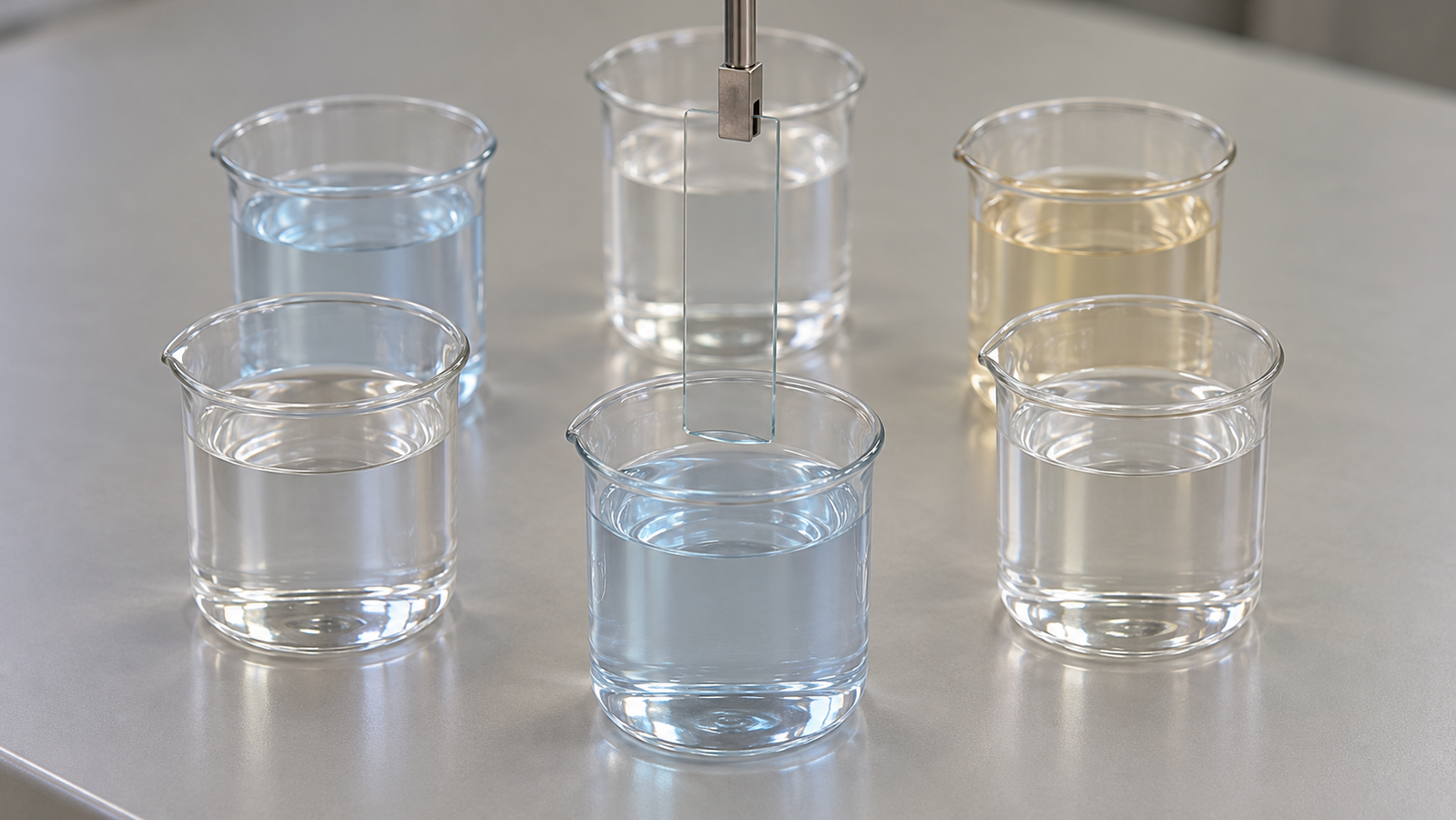
A carousel dip coater holds several baths on a turntable that rotates to bring a bath under the substrate. The six-step polyelectrolyte cycle in Section 4 maps directly onto six positions:
| Position | Bath | Purpose |
|---|---|---|
| 1 | Polycation solution | Adsorption of the positive layer |
| 2 | Rinse A1 | First rinse after the polycation |
| 3 | Rinse A2 | Second rinse after the polycation |
| 4 | Polyanion solution | Adsorption of the negative layer |
| 5 | Rinse B1 | First rinse after the polyanion |
| 6 | Rinse B2 | Second rinse after the polyanion |
An example layout, not a validated protocol. Rinse liquids, and whether rinses are buffered or salt-matched, depend on the system.
Other layouts use the same six positions differently. A tri-component film can use three adsorption baths with one rinse each. Two sols for an oxide stack leave four positions for rinses or spare baths. A single-rinse layout frees two positions for a third component.
Illustrative time budget. Assume adsorption steps of 600 s each and rinse steps of 60 s each, and ignore transfer and withdrawal time. One bilayer then takes 2 × 600 + 4 × 60 = 1,440 s, or 24 minutes. Twenty bilayers take 20 × 24 = 480 minutes, or 8 hours, before any transfer time is added. Halving the adsorption time to 300 s would bring one bilayer to 840 s (14 minutes), but only if growth per bilayer is unchanged at the shorter time, which has to be checked. Motion time is not negligible at slow withdrawal: withdrawing 30 mm at 60 mm/min takes 30 s, or 3 minutes over the six dips of one bilayer. If every position had to use the same immersion time, the rinses would run as long as the adsorption steps, and one bilayer would take 6 × 600 = 3,600 s, or 60 minutes.
The 600 s and 60 s step times are assumed values chosen to show the arithmetic. They are not recommended times for any polyelectrolyte pair and not results from Levon™ equipment.
Three practical points follow from a run of this length:
- Bath depletion and contamination. Adsorption consumes material from the polyelectrolyte baths, and every withdrawal carries liquid into the rinses. Over a long run, rinse baths become progressively contaminated. Plan when to replace them, and keep the replacement schedule part of the recipe.
- Evaporation. Open baths lose solvent over hours, which changes concentration. Covers between dips, or replenishing the baths, help.
- Geometry. The immersed length of the substrate must fit the liquid depth of the beaker, and its width must clear the beaker wall. Check this with the beakers and fill level you intend to use.
On the Levon™ DP150-DR, the product page states a six-position turntable for six standard 300 mL beakers, a turntable speed of 0.1–10 rpm, immersion and repeat-coating interval times each settable from 0 to 9,999.9 s, 1 to 999 repeat coating cycles, and 100 coating recipes that can be named, stored and recalled. The page does not describe how positions are sequenced within a recipe, or whether each position can have its own immersion time. Confirm this for your intended sequence before relying on a fully automated six-bath cycle.
9. Troubleshooting LbL and multi-bath runs
| Symptom | Likely causes | What to try |
|---|---|---|
| No growth or very slow growth | Substrate charge or cleanliness unsuitable; ionic strength or pH outside a useful range; adsorption time too short | Clean and activate the substrate; add an anchoring layer; check bath conditions; lengthen adsorption |
| Haze, particles or roughness | Polyelectrolyte complexes formed by carry-over; contaminated rinses | Refresh rinses; add a rinse step; slow withdrawal or add a drainage pause; separate rinses per component |
| Growth that drifts during a long run | Bath depletion; evaporation; rinse contamination; temperature change | Replace or replenish baths on a schedule; cover baths; record temperature |
| Thickness gradient from top to bottom | Immersion depth varies between baths; drainage pattern; uneven drying | Match fill levels; keep the substrate vertical; standardize drying |
| Poor reproducibility between runs | Untracked bath age, pH or salt; changed timings | Store and reuse the same recipe; log bath preparation and age |
| Film peels or delaminates | Weak first layer; incompatible drying; stress in thick films | Improve substrate preparation; use an anchoring layer; review the drying steps |
Typical associations from LbL practice; several causes can act together. Change one variable at a time when diagnosing.
Measuring thickness after fixed numbers of bilayers is the most useful diagnostic, because it separates growth problems from appearance problems. A dedicated article, How to Measure Thin Film Thickness: Profilometry, Ellipsometry and Interference (coming soon), will cover these methods.
10. Carousel and single-bath dip coaters compared
A single-bath dip coater can run LbL sequences if baths are changed by hand, and it remains a good choice for single-solution films. A carousel automates the change of bath. The table quotes the three Levon™ dip coater pages; “not stated” means a page does not give the value, not that the feature is absent.
| Specification | DP150-DR | DP100-BE | DP100-BE-H |
|---|---|---|---|
| Solution positions | Six-position turntable, six standard 300 mL beakers | Not stated | Not stated |
| Turntable speed | 0.1–10 rpm | Not stated | Not stated |
| Running speed | 0.1–600 mm/min | 0.1–600 mm/min | 0.1–600 mm/min |
| Stroke | Max. 240 mm | 0–100 mm (other strokes can be customized) | 0–100 mm (other strokes can be customized) |
| Displacement accuracy | ±0.1 mm | ±0.01 mm | ±0.01 mm |
| Immersion time | 0–9,999.9 s | 1–9,999.9 s | 1–9,999.9 s |
| Repeat coating interval | 0–9,999.9 s | 1–9,999.9 s | 1–9,999.9 s |
| Coating cycles | 1–999 | 1–999 | 1–999 |
| Recipes | 100, named, stored and recalled | 100, named and stored | 100, named and stored |
| Max. substrate | ≤150 × 150 × 5 mm | ≤100 × 100 × 5 mm | ≤100 × 100 × 5 mm |
| Heating | Not stated | Not stated | Heated base, RT to 120 °C, temperature controllable |
| Glovebox | Not stated | Compact structure designed for placement in a glovebox | Compact structure designed for placement in a glovebox |
| Dimensions (W × D × H) | 303 × 519 × 550 mm | 227 × 350 × 416 mm | 227 × 350 × 416 mm |
Specifications as published on the Levon™ product pages on 22 October 2026. Displacement accuracy describes positioning, not the smoothness of the withdrawal speed. The DP100-BE-H page states a heated base; it does not state the bath or substrate temperature reached. RT (room temperature) has no numeric value on the page and no cooling is stated.
For LbL sequences with two components and separate rinses, the DP150-DR Carousel Dip Coater provides six bath positions. With the stated 300 mL beakers, the beaker opening and liquid depth, rather than the 150 mm substrate limit, will in practice set the largest usable substrate, and whether each position can have its own immersion time should be confirmed (see Section 8). For single-solution films, or for short sequences where baths can be changed by hand, the DP100-BE and the heated DP100-BE-H are compact and designed for placement in a glovebox. All models are listed on the Levon™ dip coater category page.
11. Keep Exploring the Dip Coating Knowledge Hub
Start here
- Solution-Processed Thin Films: Choosing Spin, Dip, Slot-Die or Blade Coating — when dip coating is the right method, with the interactive coating method selector.
- Spin Coating Explained: Stages, Physics and Film Thickness — the stages, thickness models and defects of the main alternative to dip coating.
Dip coating process guides
- Dip Coating Explained: Withdrawal Speed, Coating Regimes and Film Thickness — stages, regimes and the speed–thickness laws.
- The Landau-Levich Equation in Practice: Viscosity, Surface Tension and Speed — how entrained thickness and carry-over scale with speed.
- Sol-Gel Dip Coating: From Sol to Dense Oxide Film (SiO2, TiO2) — sol chemistry, drying, cracking and heat treatment.
- Heated Dip Coating: How Temperature Shifts Evaporation and the Capillary Regime — temperature and evaporation in dip coating.
- How to Measure Thin Film Thickness: Profilometry, Ellipsometry and Interference (coming soon) — tracking growth per bilayer.
Links will be added as each article is published.
Levon™ dip coaters
- DP150-DR Carousel Dip Coater — six-position turntable for six standard 300 mL beakers, 0.1–600 mm/min, 240 mm maximum stroke, 100 stored recipes.
- DP100-BE Dip Coater — compact single-bath coater, 0–100 mm stroke, designed for placement in a glovebox.
- DP100-BE-H Heated Dip Coater — the same motion range with a heated base, RT to 120 °C.
- All Levon™ dip coaters — the dip coater category page.
Questions about a specific sequence, substrate or configuration can be sent through the contact form.
12. FAQ
What is layer-by-layer dip coating?
Layer-by-layer dip coating builds a film by dipping a substrate in turn into solutions of complementary species, such as a polycation and a polyanion, usually with rinses after each adsorption step. Each pair of steps adds one bilayer, and the film thickness is controlled by the solution chemistry and the number of bilayers.
Does withdrawal speed control thickness in LbL films?
Not directly. The adsorbed amount depends mainly on the chemistry of each bath. Withdrawal speed affects how much liquid is carried into the next bath: faster withdrawal entrains a thicker liquid layer. A moderate, constant speed, sometimes with a drainage pause, helps limit carry-over.
Why are rinse steps needed?
Rinsing removes loosely bound material and dilutes the solution carried out of each adsorption bath. Without it, oppositely charged species can meet in solution and form complexes that deposit as particles, causing haze and roughness. Separate rinse baths for each component reduce this risk.
Why does my film grow faster with every bilayer?
This is supralinear growth, which may be exponential. In some systems, one component can diffuse into and out of the whole film during each step, so more material is available at the surface as the film thickens. In such systems, calibrate thickness across the full range of bilayers rather than extrapolating from the first few.
How many baths do I need for layer-by-layer assembly?
A common two-component cycle uses six: polycation, two rinses, polyanion and two rinses. The DP150-DR has six bath positions, one for each of these baths; its page does not describe how the positions are sequenced or timed, so confirm this for your sequence. Fewer rinses free positions for a third component, while a single-bath coater can run the sequence with baths changed by hand.