
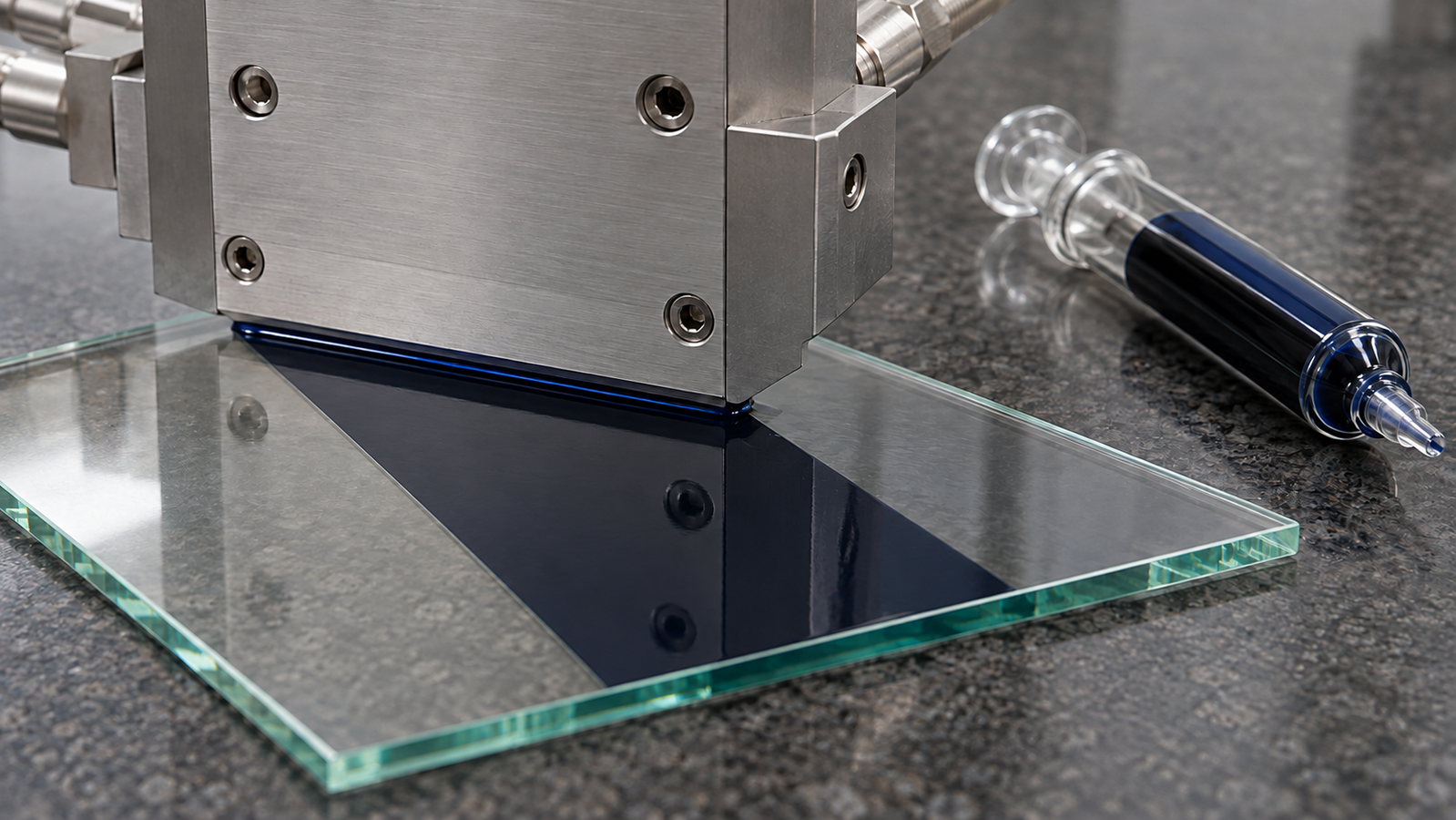
A slot-die set-up comes down to a handful of numbers: the dry thickness you want, the wet thickness that delivers it, the flow rate, the coating speed, the coated width, the gap, and how much ink the syringe must hold. Because slot-die coating is pre-metered, these numbers are linked by simple volume arithmetic. This calculator-style guide walks through each formula with units, illustrative worked numbers, and a check of the result against a lab slot-die coater’s published ranges, so the first run starts close to the target.
In one paragraph: a slot die coating calculator needs five relations. Wet thickness from a dry target: hwet = hdry/φ, where φ is the non-volatile volume fraction. Flow rate: Q = hwet·W·U. Ink volume for a coated length L: V = W·L·hwet. Syringe-limited length: Lmax = Vavail/(W·hwet). Coating time: t = L/U. In lab units, 1 µL = 1 mm3, so µL/s, mm and mm/s combine without conversion factors. The gap has no simple formula: it is a small multiple of the wet thickness, found inside the coating window.
1. The short answer: five formulas
Every slot die coating calculator, whether a spreadsheet or a few lines in a lab notebook, rests on volume conservation. Whatever the pump delivers in steady state is laid down on the substrate [1][3]. Five relations cover most set-ups:
- Dry to wet. hwet = hdry/φ, where φ is the volume fraction of material that remains after drying. This assumes a dense dried film and no change in coated width.
- Flow rate. Q = hwet·W·U. Rearranged: hwet = Q/(W·U) and U = Q/(W·hwet).
- Coated volume. V = W·L·hwet for a coated length L.
- Syringe-limited length. Lmax = Vavail/(W·hwet), where Vavail is the ink available for coating after priming, start-up and reserve allowances.
- Coating time. t = L/U, which also equals V/Q.
These relations are exact only for a steady, stable bead. They say nothing about whether the bead will be stable at the chosen numbers; that is decided by the coating window, which depends on the gap, the speed and the ink properties [2][4]. The physics behind the window is explained in Slot-Die Coating Explained: Pre-Metered Thickness and the Coating Window. For where slot-die coating sits among the solution methods, see the pillar guide to solution-processed thin films, which includes an interactive coating method selector.
2. Variables and units
Unit errors are a common source of mistakes in slot-die set-up. The table lists each variable with a convenient lab unit. The key identity is 1 µL = 1 mm3: with lengths in mm, speeds in mm/s and flow in µL/s, all five formulas work without any conversion factor.
| Symbol | Meaning | Convenient lab unit | How it is set or found |
|---|---|---|---|
| hdry | Target dry film thickness | nm or µm (convert to mm for the formulas) | Chosen by the application; measured after drying |
| φ | Non-volatile volume fraction of the ink | dimensionless (0 to 1) | Estimated from the formulation; calibrated from measured dry thickness |
| hwet | Wet film thickness | µm (0.001 mm) | Calculated; set by the pump through Q |
| W | Coated width | mm | Set by the die and any shim; measured on the film |
| U | Coating speed (relative die-substrate speed) | mm/s | Set on the coating axis |
| Q | Volumetric flow rate | µL/s (= mm3/s) | Set on the pump |
| L | Coated length | mm | Limited by substrate, stroke and ink volume |
| V | Ink volume | µL (= mm3) or mL | Calculated; plus priming and dead volume |
| G | Gap between die lips and substrate | µm | Set on the vertical axis from a zero on the substrate |
Useful conversions: 1 mL = 1,000 µL; 1 mL/min = 16.7 µL/s; 1 m/min = 16.7 mm/s; 1 µm = 0.001 mm; 1 mg/mL = 1 kg/m3 = 0.001 g/cm3.
Two cautions. W is the width of the wet film, not the nominal die width; if the film narrows as it leaves the die, the real wet thickness is larger than calculated. U is the relative die-substrate speed, whichever part moves.
3. From dry target to wet thickness
Most set-ups start from a dry thickness. The link to the wet film is the volume fraction φ of material that stays behind when the solvent evaporates. For a dense dried film of unchanged width, hdry ≈ φ·hwet [3].
Inks are usually specified by concentration or weight fraction rather than volume fraction, so a conversion is needed:
- From a concentration c (mg/mL). For a dilute ink, φ ≈ c/ρs, where ρs is the density of the dried material in the same units. Because 1 mg/mL = 0.001 g/cm3, a 100 mg/mL ink of a material with density 4 g/cm3 gives φ ≈ 0.1/4 = 0.025.
- From a weight fraction w. φ = (w/ρs) / [w/ρs + (1 − w)/ρl], where ρl is the solvent density. For w = 0.10, ρs = 4 g/cm3 and ρl = 1.1 g/cm3, φ = 0.025/(0.025 + 0.818) ≈ 0.030.
hwet = 0.0003 mm ÷ 0.030 = 0.010 mm = 10 µm.
If the dried film has a porosity p of 20%, the same wet film dries to about φ·hwet/(1 − p) = 0.3 µm/0.8 ≈ 375 nm, so a porous film needs a thinner wet layer for the same dry target. All values are assumed for illustration.
The conversion is the least certain step in the whole calculation. Solvent can remain in the film, the dried material may not reach its bulk density, and edges can shrink inward during drying. In practice, run one coating at a calculated wet thickness, measure the dry thickness at several positions, and back-calculate an effective φ for that ink, substrate and drying condition. Use the effective value for later set-ups. Thickness measurement methods are compared in How to Measure Thin Film Thickness: Profilometry, Ellipsometry and Interference.
Dilute inks need thick wet films: at φ = 0.01, a 100 nm dry film needs 10 µm wet. Very thin wet films run into the low-flow limit of the bead [5][6], so if the wet layer needed for a thin dry target sits below that limit, lowering the solids content raises the wet thickness required for the same dry target and moves the operating point away from the limit; dilution also changes the viscosity and the solvent load to dry, so recheck the coating window.
4. Flow rate, speed and width
With the wet thickness known, the flow rate follows from Q = hwet·W·U. Width is usually fixed by the die, so in practice the calculation is a triangle of three quantities: wet thickness, flow rate and speed. Fix any two and the third follows.
| You know | You calculate | Formula (lab units) |
|---|---|---|
| hwet, W, U | Flow rate | Q [µL/s] = hwet [mm] × W [mm] × U [mm/s] |
| Q, W, U | Wet thickness | hwet [mm] = Q [µL/s] ÷ (W [mm] × U [mm/s]) |
| Q, W, hwet | Speed | U [mm/s] = Q [µL/s] ÷ (W [mm] × hwet [mm]) |
Multiply a thickness in mm by 1,000 to get µm. All three rows are the same equation rearranged.
Q = 0.010 × 50 × 10 = 5 mm3/s = 5 µL/s (0.30 mL/min).
Reverse check: 5 ÷ (50 × 10) = 0.010 mm. At the same flow rate, slowing to 5 mm/s doubles the wet thickness to 20 µm; at the same speed, raising the flow to 7.5 µL/s gives 15 µm. The die width of 50 mm is an assumed value.
Which variable to adjust. Because thickness depends on the ratio Q/U, a thickness change can be made with either knob, but the two are not equivalent for the bead. Changing U changes the capillary number Ca = μU/σ and therefore where the operating point sits in the coating window; changing Q at fixed U moves the point along the wet-thickness axis only [6][2]. A practical approach is to choose a speed that gives a stable bead and an acceptable drying time, then fine-tune thickness with flow rate.
Speed and drying. Slower coating gives volatile solvents more time to evaporate near the bead and edges; faster coating raises the capillary number toward air entrainment. Speed is a compromise between the window and drying, not a free choice.
Width. If the die can be fitted with different shims, a narrower coating at the same Q and U gives a thicker film. Stripe coating with a shimmed die divides the flow among several lanes, and the edges of each lane behave differently from the centre [7]. For calculations, use the sum of the coated lane widths, not the die width.
5. Ink volume, coating time and syringe-limited length
The coated volume is V = W·L·hwet, and the coating time is t = L/U. In lab units, mm × mm × mm gives mm3, which equals µL.
V = 50 × 150 × 0.010 = 75 mm3 = 75 µL.
t = 150 ÷ 10 = 15 s, and 75 µL ÷ 5 µL/s = 15 s, which agrees.
The coated volume is only part of what the syringe must hold. The total is:
Vprime fills the tubing, fittings, die manifold and slot; Vstart forms the bead and covers any start-up length; Vreserve keeps the syringe from running empty, which would draw air into the line.
For a small lab coating, the priming volume usually dominates. The coated film in the example above holds 75 µL, while the internal volume of tubing and die can be much larger, depending on tubing bore and length and on the die cavity. Measure it once for your set-up, for example by weighing the ink needed to fill the system from empty, and record it with the die and tubing configuration. Short, narrow tubing and a small manifold reduce the priming volume; they matter more for expensive inks than any change in coating speed.
Syringe-limited length. Rearranging gives the longest coating one fill can make: Lmax = Vavail/(W·hwet), where Vavail is the ink available for coating after priming, start-up and reserve allowances. Two contrasting cases show when the syringe, rather than the substrate or the stroke, limits a run:
| Case (illustrative) | Vavail | W | hwet | Lmax | What limits the run |
|---|---|---|---|---|---|
| Thin functional film | 1 mL (1,000 mm3) | 100 mm | 10 µm | 1,000 mm | Substrate length or axis stroke, not ink |
| Thick paste or slurry layer | 1 mL (1,000 mm3) | 100 mm | 100 µm | 100 mm | Ink volume; a larger fill is needed |
Values assumed for illustration. Lmax = 1,000 mm3 ÷ (100 mm × hwet in mm).
For thin films the ink volume rarely limits a single coating; the limits are the substrate size and the travel of the coating axis. For thick layers, such as electrode slurries, the syringe can run out before the end of the substrate, and the pump capacity becomes a real constraint.
6. Choosing the gap
The gap is the one set-up parameter without a simple formula. It does not appear in hwet = Q/(W·U), but it decides whether that thickness can be coated at all. The low-flow limit, the thinnest wet film a bead can sustain at a given speed, is usually expressed in terms of the ratio of gap to wet thickness and the capillary number [5][4][8]. In the low-Ca, low-Reynolds-number regime, lower Ca generally permits a larger gap-to-thickness ratio; this trend need not hold when inertia becomes important [6][2].
A practical approach to the gap:
- Start with a gap a small multiple of the wet thickness. Ratios between roughly one and a few are common starting points in published work; the right value depends on the ink, the die-lip geometry and whether bead vacuum is used [4][8][2]. Treat any ratio as a starting point to be tested, not a specification.
- Zero the gap on the substrate. Use the manufacturer’s approved zeroing method on the mounted substrate. This accounts for the substrate thickness at the reference point; bow, tilt and height variation still affect the gap across the coating area.
- Adjust in small steps. If the film breaks into stripes or rivulets, reduce the gap or raise the flow; if liquid leaks upstream, reduce excess flow or bead vacuum and reassess the gap.
- Record the working range. Note the smallest and largest gaps at which a uniform film forms for each speed. Over several inks, this becomes a lab-specific map of the coating window.
Gap and mechanical accuracy. A gap error does not change the pre-metered thickness, but it moves the operating point within the window. The relative error is what matters: a ±2 µm variation is about ±4% of a 50 µm gap but ±20% of a 10 µm gap. Very small gaps therefore demand a flat substrate, a flat, parallel die and a repeatable vertical axis, and they increase the risk of the die touching particles or the substrate.
Bead vacuum. Where a die is fitted with an upstream vacuum box, a slight under-pressure on the upstream meniscus typically allows thinner films or larger gaps at a given speed, within its own limits [4][2]. It is a feature of the die set-up and is different from vacuum that holds the substrate flat on the stage.
7. Checking against published ranges
Once Q, U, L and V are calculated, check each against the instrument. The table quotes the Levon™ SD200 and SD300 product pages; “not stated” means the page does not give the value, not that the feature is absent.
| Specification | SD200 | SD300 | Calculator variable it limits |
|---|---|---|---|
| Compatible substrate area | 200 × 200 mm | 300 × 300 mm | W and L |
| Compatible substrate thickness | 0.05–10 mm | 0.05–10 mm | Substrate choice |
| Coating platform | 260 × 260 mm granite platform, vacuum adsorption | 360 × 360 mm granite platform, vacuum adsorption | Substrate hold-down |
| Y-axis speed | 0.002–50 mm/s | 0.002–50 mm/s | U |
| Y-axis stroke | 0–355 mm | 0–450 mm | L plus start and stop lengths |
| Z-axis | 0.001–20 mm/s; synchronous repeatability ±0.002 mm | 0.001–20 mm/s; synchronous repeatability ±0.002 mm | G |
| Contact detection | Accuracy 1 µm | Accuracy 1 µm | Gap zero |
| Injection pump control | Capacity control 0–10 mL; output speed control 0–1000 µL/s | Capacity control 0–10 mL; output speed control 0–1000 µL/s | Q and V |
| Slot-die head width | Not stated | Not stated | W |
| Bead vacuum | Not stated | Not stated | Gap and window |
| Heated platform | Not stated | Not stated | Drying |
Specifications as published on the Levon™ SD200 and SD300 product pages on 22 October 2026. The pages do not label which axis carries the coating motion; the Y-axis, with the longer stroke, is the likely candidate, but confirm this before planning coated lengths. The platform vacuum adsorption holds the substrate; it is not bead vacuum. Because the head width is not stated, every worked example here uses an assumed width.
A worked range check (illustrative). For the section 4 example, Q = 5 µL/s lies well inside 0–1000 µL/s, U = 10 mm/s inside 0.002–50 mm/s, and a 150 mm coating plus start and stop lengths inside a 355 mm stroke. The upper end of the pump range is rarely the constraint for thin films: even 100 µm wet over an assumed 100 mm width at 50 mm/s needs 500 µL/s. The lower end deserves more attention. A 2 µm wet film over an assumed 20 mm width at 0.5 mm/s needs only 0.02 µL/s. The pages do not specify low-flow resolution or smoothness. Verify mean flow by timed weighing with ink density and evaporation accounted for; assess pulsation separately.
8. Sensitivity and error budget
Because hwet = Q/(W·U) is a simple product and quotient, small relative errors add. To first order:
For the dry film, add the relative uncertainty in φ: δhdry/hdry ≈ δhwet/hwet + δφ/φ.
In many lab set-ups the largest terms are not the pump or the axis set-points but:
- The volume fraction φ. An estimate from the recipe can differ from an effective value because of porosity, residual solvent and density. Calibrate it for the ink, substrate and drying conditions.
- The coated width. Edge narrowing and thick edge bands change the effective width [7]. Use the actual wet coated width in the volume balance; assess the useful dry area separately, excluding edge bands.
- Transients. The pump and the line need time to reach steady flow, and compliance in the syringe, tubing and any trapped air delays both start and stop. Thickness near the leading and trailing edges can differ from the steady value even when the set-points are right [9].
- Temperature. Ink viscosity and surface tension change with temperature. They do not change the pre-metered thickness, but they shift the coating window through the capillary number.
9. A worked set-up, start to finish
The example below runs through a complete set-up. All numbers are assumed for illustration; they are not a recipe for any particular ink or a result from any instrument.
- Target. 400 nm dense dry film over a 150 × 150 mm useful area on a glass plate.
- Ink. A dilute precursor ink with an effective φ = 0.040, calibrated from a previous coating.
- Wet thickness. hwet = 0.0004 mm ÷ 0.040 = 0.010 mm = 10 µm.
- Width. Die and shim give an assumed coated width of 160 mm, leaving 5 mm edge bands on each side of the useful area.
- Speed. Choose U = 5 mm/s as a moderate starting speed. Ca at μ = 3 mPa·s and σ = 30 mN/m is 0.003 × 0.005 ÷ 0.030 = 5 × 10⁻⁴.
- Flow rate. Q = 0.010 × 160 × 5 = 8 µL/s (0.48 mL/min).
- Length and time. Coat 170 mm (150 mm useful plus 10 mm at each end for transients): t = 170 ÷ 5 = 34 s.
- Volume. Vcoat = 160 × 170 × 0.010 = 272 µL. Add the measured priming volume for the die and tubing, a start volume and a reserve; if priming takes 1.5 mL, load at least about 2 mL.
- Gap. Start at a gap a small multiple of 10 µm, zeroed on the glass surface, then adjust in small steps while watching the bead.
- Range check. 8 µL/s, 5 mm/s and about 200 mm of travel lie inside the SD200 page ranges quoted in section 7; the coated width of 160 mm and a 170 mm coated length fit a 200 × 200 mm substrate area. The head width must be confirmed separately.
- Measure and correct. Measure dry thickness at a grid of points inside the useful area. If the mean is 440 nm, the effective φ is 0.044; for the next run, reduce Q to 8 × 400/440 ≈ 7.3 µL/s at the same speed.
Drying is outside the calculator but decides the film morphology. Many functional inks, especially perovskite precursors, need controlled drying after slot-die coating, such as gas quenching or heating, and scalable slot-die processes reported for perovskite solar cells combine the coating step with such drying control [10]. Drying is covered in Air-Knife and Gas Quenching for Blade- and Slot-Die-Coated Films, and transferring a spin-coating ink in From Spin Coating to Slot-Die and Blade: Scaling a Thin-Film Ink.
10. Quick-reference table
The table gives the flow rate for a few combinations of wet thickness and speed over an assumed 100 mm coated width. For another width, scale Q in proportion: a 50 mm width needs half the tabulated value.
| Wet thickness | U = 1 mm/s | U = 5 mm/s | U = 10 mm/s | U = 25 mm/s | Ink per 100 mm length |
|---|---|---|---|---|---|
| 2 µm | 0.2 µL/s | 1 µL/s | 2 µL/s | 5 µL/s | 20 µL |
| 5 µm | 0.5 µL/s | 2.5 µL/s | 5 µL/s | 12.5 µL/s | 50 µL |
| 10 µm | 1 µL/s | 5 µL/s | 10 µL/s | 25 µL/s | 100 µL |
| 25 µm | 2.5 µL/s | 12.5 µL/s | 25 µL/s | 62.5 µL/s | 250 µL |
| 50 µm | 5 µL/s | 25 µL/s | 50 µL/s | 125 µL/s | 500 µL |
| 100 µm | 10 µL/s | 50 µL/s | 100 µL/s | 250 µL/s | 1,000 µL |
Calculated from Q = hwet·W·U with W = 100 mm (assumed). Ink per length excludes priming and start-up volume. Whether each combination can be coated depends on the coating window for the ink, gap and die.
11. Keep Exploring the Slot-Die and Blade Coating Knowledge Hub
Start here
- Solution-Processed Thin Films: Choosing Spin, Dip, Slot-Die or Blade Coating — when slot-die coating is the right method, with the interactive coating method selector.
- Spin Coating Explained: Stages, Physics and Film Thickness — the usual starting point for inks that later move to slot-die coating.
Slot-die and blade coating guides
- Slot-Die Coating Explained: Pre-Metered Thickness and the Coating Window — the physics behind the formulas and the coating window.
- Doctor Blade Coating: Blade Gap vs Wet Film Thickness — the self-metered alternative with a fixed gap.
- Wire-Bar (Mayer Rod) Coating: Wire Diameter and Wet Film Thickness — wet thickness set by the rod geometry.
- From Spin Coating to Slot-Die and Blade: Scaling a Thin-Film Ink — reformulating and transferring an ink.
- Air-Knife and Gas Quenching for Blade- and Slot-Die-Coated Films — controlling how the wet film dries.
Links will be added as each article is published.
Levon™ slot-die coaters
- SD200 Slot-Die Coater — 200 × 200 mm compatible substrate area, Y-axis 0.002–50 mm/s over 0–355 mm, injection-pump control 0–10 mL and 0–1000 µL/s.
- SD300 Slot-Die Coater — 300 × 300 mm compatible substrate area, 360 × 360 mm granite platform, Y-axis stroke 0–450 mm.
- All Levon™ slot-die coaters — the slot-die coater category page.
Questions about a specific ink, substrate or configuration can be sent through the contact form.
12. FAQ
How do I calculate the flow rate for slot-die coating?
Multiply the wet thickness by the coated width and the coating speed: Q = hwet·W·U. With thickness and width in mm and speed in mm/s, the result is in mm3/s, which equals µL/s. For example, with illustrative values, 10 µm wet over 50 mm at 10 mm/s needs 5 µL/s.
How do I get the wet thickness from a target dry thickness?
Divide the dry thickness by the non-volatile volume fraction of the ink: hwet = hdry/φ. For a dilute ink, φ is roughly the concentration divided by the density of the dried material. Porosity and residual solvent make the estimate uncertain, so calibrate φ from a measured film.
How much ink do I need in the syringe?
The coated film needs W·L·hwet; for 50 × 150 mm at 10 µm that is 75 µL. Add the volume needed to fill the tubing, die and bead, plus a reserve so the syringe never runs empty. For small lab coatings, the priming volume is usually larger than the coated volume.
Can the calculator tell me the gap?
No. The gap does not appear in the pre-metered formula; it decides whether the bead is stable. Start with a gap a small multiple of the wet thickness, zeroed on the substrate surface, and adjust in small steps. The workable range depends on the capillary number, the die geometry and whether bead vacuum is used.
Why is my measured thickness different from the calculation?
The most common causes are an estimated volume fraction that differs from the effective one, a coated width narrower than the die width, start and stop transients, and porosity in the dried film. Outside the coating window, the formula no longer predicts a uniform local thickness. Measure, recalculate an effective volume fraction, and correct the flow rate.