
A blade or slot die lays down a wet film in a fraction of a second, but for many functional inks, perovskites above all, the way that film dries decides what the dry film looks like. In still air it can dry slowly, so crystals may grow from a few scattered nuclei. An air knife blowing nitrogen or dry air can accelerate evaporation and promote dense nucleation when matched to the ink. This guide treats gas quenching as a mass-transfer problem: how gas speed, knife height, angle and timing change the evaporation rate, and how to set up an air knife on a lab film applicator.
In one paragraph: early evaporation can be limited by how fast solvent vapour is carried away. The flux is j = k·(cs − c∞), where cs is the saturated vapour concentration at the surface, c∞ the background concentration and k a mass-transfer coefficient. In still air k is small; a gas flow thins the vapour layer, and for laminar parallel flow k grows roughly with the square root of gas speed [5]. The illustrative parallel-flow model gives an order-of-magnitude increase in early evaporation; it does not predict a particular knife’s performance or the resulting nucleation density. Knife height, angle, timing, gas, substrate temperature and solvent all shift the result.
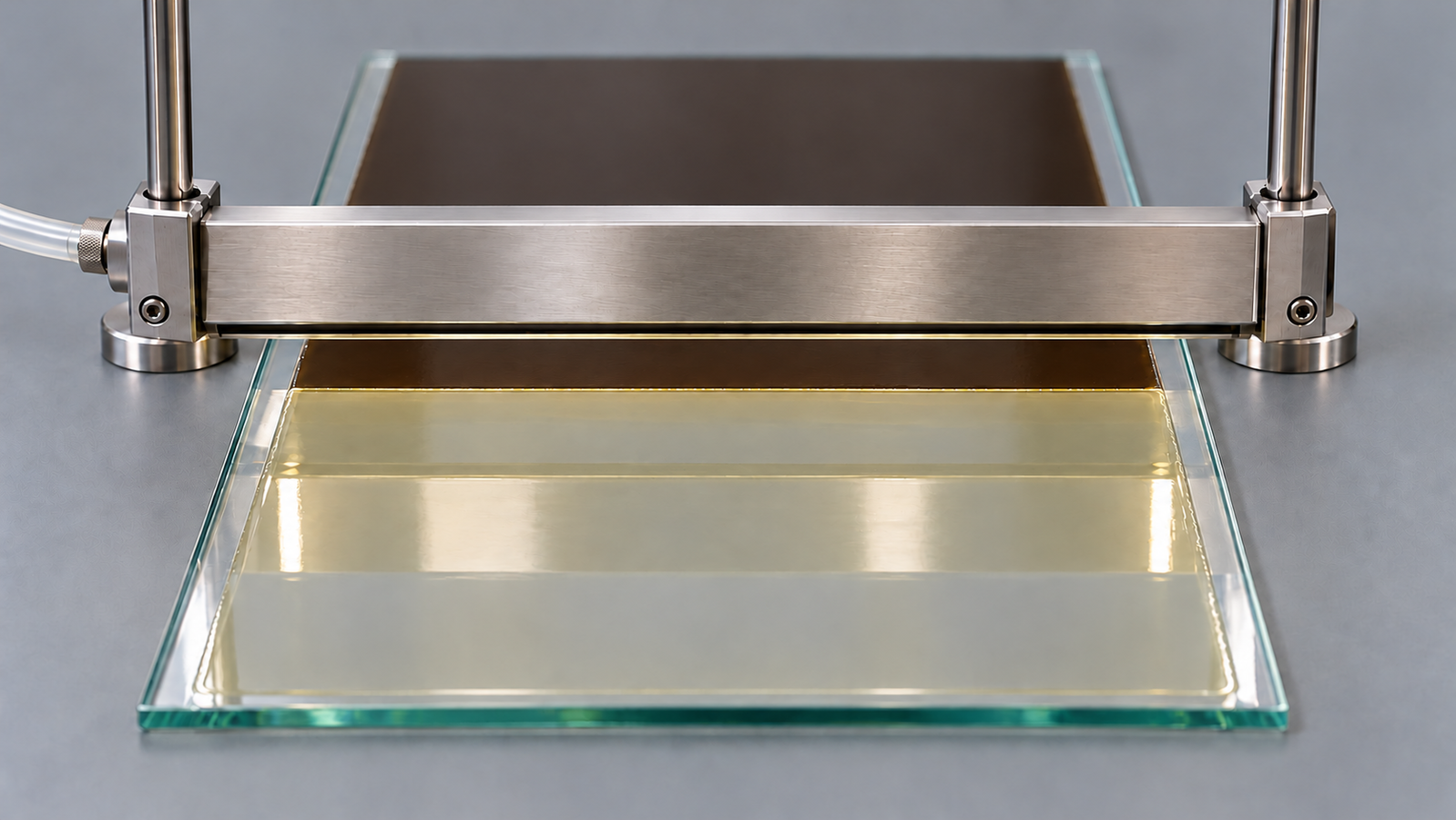
1. The short answer
Interest in gas quenching perovskite films usually starts with one problem: an ink that gives dense films on a spin coater gives hazy or pinholed films on a coater, where nothing sweeps the vapour away. The options compare as follows:
| Drying condition | What limits evaporation | Typical outcome for a crystallising ink |
|---|---|---|
| Still air or still glovebox atmosphere | Diffusion of vapour through a thick, stagnant layer | Slow drying; few nuclei grow into large, separated crystals, leaving gaps |
| Gentle, uncontrolled draught | Weak, uneven convection | Faster but non-uniform drying; patterns follow the air flow |
| Air knife or gas quench | Thin, controlled boundary layer under a gas jet | Faster, more even supersaturation; can give dense nucleation and a continuous film when matched to the ink [1][2] |
| Heated substrate | Higher vapour pressure at the film surface | Faster drying; combinable with gas flow; can also change crystal phase |
General trends; outcomes depend strongly on the ink and substrate.
The air knife works in line: it follows the blade or slot die at a fixed distance and treats every part of the film the same way. For the wider picture of why spin recipes need changing on coaters, see From Spin Coating to Slot-Die and Blade: Scaling a Thin-Film Ink. For how blade and slot-die coating compare with spin and dip coating overall, the pillar guide to solution-processed thin films includes an interactive coating method selector.
2. Why drying speed decides the film
A solute crystallises when its concentration exceeds solubility by enough to form stable nuclei. In the classic LaMer and Dinegar picture, the concentration rises past a critical supersaturation, a short burst of nucleation lowers it again, and the nuclei then grow with few new ones forming [6]. The picture was developed for particles in solution but is widely applied to drying films.
In a simplified nucleation picture, evaporation raises solute concentration, and its rate can influence the number of nuclei:
- Slow rise. Few nuclei form and grow by drawing solute from around them, giving large, isolated crystals or dendrites with bare substrate between.
- Fast rise. Many nuclei form at once across the film and meet before any grows large, giving a dense, continuous layer of small grains that annealing can later coarsen.
Antisolvent dripping in spin coating achieves the fast rise chemically, by lowering the solubility in one step [7]. Gas quenching achieves it physically, by removing solvent quickly. Gas-assisted spin coating was shown to give perovskite films consisting of a monolayer of single-crystalline grains [3], and a gas-quenching protocol was reported to work across several hybrid lead halide perovskite compositions [2]. A perspective on the method highlights that it needs no antisolvent and no timed drip [1].
3. Evaporation as mass transfer
During early drying, gas-side transport can control evaporation. The examples assume a solvent-rich single-solvent ink, negligible background vapour and fixed film temperature; solvent activity and evaporative cooling can modify actual rates. In this approximation, the flux per unit area is:
j: mass flux (kg m−2 s−1); k: mass-transfer coefficient (m/s); cs: saturated vapour mass concentration at the surface; c∞: vapour concentration in the bulk gas; psat: solvent vapour pressure at the film temperature; M: molar mass; R: gas constant; T: absolute temperature.
This separates the two ways to speed up drying: heating raises psat and so cs; gas flow raises k and keeps c∞ near zero. In perovskite work, in situ measurements in a drying channel with laminar dry-air flow at varied temperature and gas velocity have been combined with a quantitative drying model of this kind [8].
k depends on the vapour diffusion coefficient D and the layer it must cross: for a stagnant layer of thickness δ, k ≈ D/δ.
Diffusion coefficients. The Fuller–Schettler–Giddings correlation estimates gas-phase diffusion coefficients from molar masses and tabulated atomic diffusion volumes [9]. For common polar solvents such as DMF, DMSO or 2-methoxyethanol in nitrogen at room temperature and atmospheric pressure it gives values of about 1 × 10⁻⁵ m2/s (0.10–0.12 cm2/s). That value is used in the examples below.
Minutes of slow drying are ample time for a few nuclei to grow into large, isolated crystals, and the poorly defined stagnant layer makes the result sensitive to every draught in the room.
4. How gas speed raises evaporation
When gas flows over the film, the vapour is swept away within a thin concentration boundary layer. For laminar flow along a flat plate, boundary-layer theory gives the average mass-transfer coefficient over a length L through the Sherwood number [5]:
U: gas speed over the film; L: length of film swept by the flow; ν: kinematic viscosity of the gas (about 1.5 × 10⁻⁵ m2/s for nitrogen or air at room temperature). Rearranged, k ∝ U1/2·L−1/2·D2/3·ν−1/6. The relation holds for laminar flow, roughly Re below a few hundred thousand.
The square-root dependence is the key practical point. Doubling the gas speed raises the evaporation rate by only about 40%; a tenfold increase raises it about threefold. The coefficient is highest where the flow first meets the film and falls downstream as the boundary layer thickens.
| Gas speed over the film | Re (L = 50 mm) | Sh | k | Relative to still gas (k ≈ 2 mm/s) |
|---|---|---|---|---|
| 0.1 m/s | about 320 | about 14 | about 2.8 mm/s | about 1.4× |
| 1 m/s | about 3,200 | about 44 | about 8.7 mm/s | about 4× |
| 5 m/s | about 16,000 | about 98 | about 20 mm/s | about 10× |
| 10 m/s | about 32,000 | about 138 | about 28 mm/s | about 14× |
| 20 m/s | about 65,000 | about 195 | about 39 mm/s | about 20× |
Assumed values: D = 1.0 × 10⁻⁵ m2/s, ν = 1.55 × 10⁻⁵ m2/s (Sc ≈ 1.55), L = 50 mm; still-gas reference from section 3 with δ = 5 mm. The flat-plate formula ignores the impinging jet, natural convection and the vapour’s own effect on the gas, so the numbers are orders of magnitude, not predictions.
An air knife produces an impinging jet, so the parallel-flow table does not predict its local or average transfer coefficient. Impinging-jet transfer depends on slot width, nozzle distance, angle and jet Reynolds number; relevant correlations were reviewed by Martin [10]. Those correlations were developed for nozzles within a few tens of slot widths of the surface and jet Reynolds numbers in the thousands; a 0.05 mm slot held 10–35 mm above the film at flows of a few litres per minute lies far outside that range. Measure the drying under a particular knife, for example by timing the visible change of the film, rather than calculating it.
5. Air knife geometry: slit, height and angle
An air knife is a manifold that feeds gas from one or more inlets to a long, narrow outlet slot. Three settings matter: the slit, the height and the angle.
Slit and gas flow. For a slot of length Ws and clearance b, the mean exit speed is roughly the actual volume flow at outlet conditions divided by the slot area: U0 ≈ Q/(Ws·b). The ideal pressure needed to reach that speed is the dynamic pressure, ½ρU02; real knives need more because of losses in the manifold and slot.
| Gas flow Q | Exit speed, 180 mm × 0.05 mm slot | Ideal dynamic pressure at 180 mm slot |
|---|---|---|
| 2 L/min | about 3.7 m/s | about 8 Pa |
| 5 L/min | about 9.3 m/s | about 50 Pa |
| 10 L/min | about 19 m/s | about 200 Pa |
| 20 L/min | about 37 m/s | about 790 Pa |
Arithmetic only: U0 = Q/(Ws·b) and ½ρU02 with ρ = 1.15 kg/m3. The outlet lengths and 0.05 mm clearance match published Levon™ air knife module dimensions (section 10); the gas flows are assumed, since no flow rate or supply pressure is published. Ignores compressibility and manifold losses.
For the same flow, a shorter slot gives a faster jet, and even modest flows give several metres per second at the outlet; the question is how much of that speed reaches the film.
Height above the substrate. As a slot jet travels towards the film, it entrains surrounding gas and spreads. Increasing the knife height often broadens the drying zone and reduces its peak intensity, but the change depends on the nozzle, gas flow, angle and flow regime [10]. Compare heights at fixed flow and angle, observing both drying uniformity and film disturbance.
Angle. A knife pointing straight down splits its flow in two directions along the film. Tilting it sends most of the gas one way. Tilting away from the coating head, so the gas flows over the already-coated film and not back towards the wet meniscus, keeps the meniscus from drying out or being disturbed. Gas backflow is a recognised concern: in a study of gas quenching of slot-die-coated perovskite modules with a flow-controlled, oblique impinging slot nozzle purged with nitrogen, the authors derived slot-jet adjustments that prevent gas backflow [11].
Coverage across the width. The useful part of the knife is the outlet length, not the overall body length. The gas sheet weakens near the slot ends, so the outlet should exceed the coated width by a margin; otherwise the edges can dry more slowly than the centre.
6. Timing on a moving coater
On a coater the knife usually follows the coating head at a fixed distance. Two times then follow from the geometry and the coating speed Uc:
- Delay between deposition and quench: td = dbk/Uc, where dbk is the distance from the coating line to the knife’s impact line.
- Exposure to the intense part of the jet: te ≈ wz/Uc, where wz is the width of the drying zone along the coating direction.
| Coating speed Uc | Delay, dbk = 20 mm | Delay, dbk = 40 mm | Exposure, wz = 20 mm |
|---|---|---|---|
| 5 mm/s | 4 s | 8 s | 4 s |
| 10 mm/s | 2 s | 4 s | 2 s |
| 25 mm/s | 0.8 s | 1.6 s | 0.8 s |
| 50 mm/s | 0.4 s | 0.8 s | 0.4 s |
Arithmetic only: time = distance ÷ speed. Distances and zone width are assumed for illustration.
The table shows a coupling that is easy to miss: changing the coating speed to change the wet thickness also changes both the delay and the exposure. Faster coating shortens the delay, useful if the ink starts nucleating on its own, but also the exposure. When the coating speed changes, re-check the knife distance or gas flow.
For scale only: if the film dried at the illustrative parallel-flow rate of section 4, a 2 s exposure would remove about 1 µm of a 10 µm wet film, raising the average solute concentration by only about a tenth. The actual rate under a knife must be measured, and a short pass is enough only if the ink is already close to saturation or the surface layer supersaturates first. Otherwise a thinner wet film, a more volatile solvent, a heated plate or a longer exposure (lower coating speed or a wider drying zone) has to make up the difference.
Blade coating examples. In fully air-bladed perovskite films, an air-blading process both coated the film and induced nucleation without an antisolvent [12]. In room-temperature blading with a nitrogen knife behind the blade at a fixed distance, an ink whose solvent was mostly volatile and non-coordinating, with a little coordinating solvent, allowed blading at up to 99 mm/s [13]. Both matched the ink to the gas flow.
Slot-die examples. A slot-die head holds a liquid bead in the gap, so gas directed back towards it could disturb the bead or dry ink on the die lips; keeping the gas flowing away from the head is a sensible default. Slot-jet adjustments that prevent gas backflow were part of the slot-die gas-quenching process of section 5 [11]. The pre-metered side of slot-die coating is covered in Slot-Die Coating Explained: Pre-Metered Thickness and the Coating Window, and the blade side in Doctor Blade Coating: Blade Gap vs Wet Film Thickness.
7. Gas, temperature and solvent
Which gas. Nitrogen is the usual choice for moisture- or oxygen-sensitive inks, including most perovskite precursors. Dry, filtered compressed air works for inks that tolerate oxygen and is cheaper to supply. Either way the gas must be dry and clean: hygroscopic inks absorb water from humid gas, and oil or particles from an unfiltered supply land on the wet film. D, and therefore k, differs little between nitrogen and air.
Substrate temperature. A heated substrate raises psat at the film surface; the vapour pressure of a liquid rises roughly exponentially with temperature, as described by the Clausius–Clapeyron relation. In the illustrative parallel-flow model with negligible background vapour, doubling the surface vapour pressure and quadrupling the gas speed would raise the early evaporation rate about fourfold. Heating also offsets evaporative cooling, but it affects crystal phase and solvent complexes too, so treat it as a separate variable. The temperature dependence of evaporation is discussed for dip coating in Heated Dip Coating: How Temperature Shifts Evaporation and the Capillary Regime.
Solvent. The ink sets the target. A high-boiling, strongly coordinating solvent evaporates slowly and may hold the solute in intermediate complexes, so it needs more drying effort; a volatile, weakly coordinating solvent dries quickly even under modest gas flow. Reformulating with a larger fraction of volatile solvent is often what makes a knife effective at high coating speeds, as in the high-speed blading example of section 6 [13].
8. Troubleshooting gas-quenched films
| Symptom | Likely cause | First thing to try |
|---|---|---|
| Hazy or grey film with uncovered areas | Quench too weak or too late; slow nucleation | Raise gas flow, lower the knife, or shorten the delay |
| Ripples or wave marks across the coating direction | Jet momentum deforms the still-liquid film | Lower the gas flow, raise the knife or tilt it to reduce normal impact |
| Good centre, poor edges | Weaker gas sheet near the slot ends, uneven gas flow, or a thicker wet film at the edges | Check outlet margin, gas uniformity and edge wet thickness; then try a longer outlet or a narrower coating |
| Streaks along the coating direction | Uneven gas sheet from a blocked or damaged slot, or particles in the gas | Clean the slot, filter the gas, check the gas sheet with a light tissue |
| Ink dries on the blade or die lips | Gas backflow towards the coating head | Tilt the knife away from the head, increase the distance |
General diagnostic guide. Causes overlap; change one parameter at a time. Defects caused by the coating flow itself, such as ribbing, are covered in the coating defect literature [14].
The first two rows are two sides of one balance: too little gas leaves the film to nucleate slowly, too much pushes it around before it sets. The window between them depends on the film’s viscosity and thickness when it reaches the knife.
9. Setting up a first air-knife run
A practical sequence on a film applicator with an air knife, with all numbers to be adapted to the ink:
- Coat without gas first. Find a gap or flow rate and speed that give a uniform wet film; dry it in still gas as a baseline.
- Choose the knife. Pick an outlet longer than the coated width; mount it a fixed distance behind the coating head.
- Set height and angle. Start in the middle of the available range, for example about 20 mm high, tilted slightly away from the coating head.
- Set the gas. Use dry nitrogen for sensitive inks. Start a moderate, constant flow before the stroke and record the flow or supply pressure.
- Coat and inspect. A well-quenched perovskite film often changes visibly, for example from transparent to a uniform darker film, within or just after the jet zone. Note where along the stroke the change occurs.
- Adjust one lever at a time. If drying is too slow, raise the flow or lower the knife; if the film ripples, do the opposite. Then fine-tune delay with knife distance and coating speed.
- Record everything. Gas flow, height, angle, distance, coating speed and plate temperature form one recipe.
An unrecorded change in supply pressure or knife height is a common reason a gas-quenching recipe stops working. For the spin-coating baseline used for many perovskite inks, see Perovskite Film Fabrication: Spin Coating, Antisolvent Timing and Annealing.
10. Levon™ film applicators with an air knife
The table quotes the Levon™ PF200-H and PF400 / PF400-H product pages. “Not stated” means the page does not give the value, not that the feature is absent.
| Specification | PF200-H | PF400 / PF400-H |
|---|---|---|
| Coating speed | 1–50 mm/s (1 mm/s regulation accuracy) | 1–300 mm/s (1 mm/s regulation accuracy) |
| Stroke length | 250 mm | 420 mm maximum |
| Vacuum panel | 380 × 210 mm; A4 adsorption area | 540 × 345 mm; A4/A3 adsorption area, optional |
| Heated panel | RT to 200 °C; 1–10 °C/min; thermal uniformity ≤±1.5% | PF400-H: RT to 200 °C; ±0.5 °C control accuracy; ≤±4% uniformity. PF400: heating not stated |
| Coating tools | Adjustable film scraper, four-sided coater, wire rod | Adjustable film scraper or standard wire rod |
| Air knife lengths | 80, 100, 150 and 200 mm modules | 150, 200, 270 and 320 mm modules |
| Air outlet lengths | 60, 80, 130 and 180 mm | 130, 180, 250 and 300 mm |
| Air outlet clearance | 0.05 mm | 0.05 mm |
| Air inlets | 1 (80 and 100 mm knives) or 2 (150 and 200 mm knives); 6 mm inlet pipe | 2; 6 mm inlet pipe |
| Knife angle and height | Angle −45° to 45°; 10–35 mm above the substrate | Not stated |
| Gas flow, supply pressure, jet speed | Not stated | Not stated |
| Gas type | Not stated | Not stated |
| Glovebox operation | Not stated | Not stated |
Specifications as published on the Levon™ PF200-H and PF400 product pages on 22 October 2026. Air knife modules are listed on the pages as compatible modules; the supplied configuration is confirmed in the quotation. The PF400 page states that external utilities, where required, are supplied by the user.
How this connects to the guide: outlet lengths decide which coating widths are covered with margin, the PF200-H angle and height adjustments let the drying zone be tuned, the speed range sets the times of section 6, and the heated panel adds the temperature lever of section 7.
11. Keep Exploring the Slot-Die and Blade Coating Knowledge Hub
Start here
- Solution-Processed Thin Films: Choosing Spin, Dip, Slot-Die or Blade Coating — how the methods compare, with the interactive coating method selector.
- Spin Coating Explained: Stages, Physics and Film Thickness — why spin coating dries films so quickly, the reference point for gas quenching.
Slot-die and blade coating guides
- From Spin Coating to Slot-Die and Blade: Scaling a Thin-Film Ink — why drying must change when an ink moves to a coater.
- Doctor Blade Coating: Blade Gap vs Wet Film Thickness — setting the wet film the knife then dries.
- Slot-Die Coating Explained: Pre-Metered Thickness and the Coating Window — the pre-metered alternative.
- Perovskite Film Fabrication: Spin Coating, Antisolvent Timing and Annealing — the antisolvent route that gas quenching replaces.
Links will be added as each article is published.
Levon™ film applicators
- PF200-H Heated Film Applicator — heated vacuum panel, adjustable angle and height air knife modules with 60–180 mm outlets.
- PF400 Film Applicator (PF400 and PF400-H) — 1–300 mm/s, 540 × 345 mm vacuum panel, air knife modules with 130–300 mm outlets.
- All Levon™ film applicators — the film applicator category page.
Questions about a specific ink, substrate or configuration can be sent through the contact form.
12. FAQ
What does gas quenching do to a perovskite film?
It accelerates solvent removal and can promote rapid supersaturation and dense nucleation. Film continuity still depends on the ink, wetting and drying conditions. In a suitably developed process it can replace the antisolvent drip used in spin coating.
Should I use nitrogen or compressed air in an air knife?
Use dry nitrogen for moisture- or oxygen-sensitive inks such as most perovskite precursors. Clean, dry, filtered air works for tolerant inks. The drying effect itself is similar for both gases; what matters is that the gas is dry and free of oil and particles.
How high should the air knife be above the substrate?
Start within the permitted range for the module and compare heights at fixed gas flow and angle. Increasing height often broadens the drying zone and reduces peak intensity, but the effect must be checked for the actual nozzle and ink.
Does coating speed affect gas quenching?
Yes. At a fixed knife position, the delay between coating and quenching and the time the film spends under the jet both scale inversely with coating speed. Changing speed to change thickness therefore also changes the quench, so re-check gas flow or knife distance.
Why does my gas-quenched film have ripples?
The jet is pushing the still-liquid film before it sets. Lower the gas flow, raise the knife or tilt it to reduce the component of the jet normal to the film, or use a slightly more viscous ink.