
Slot-die coating meters a known volume of ink through a narrow slot onto a moving substrate, so the wet film thickness is set by the flow rate, the coating width and the speed rather than by the liquid’s viscosity. The catch is the coating window: the formula holds only while the liquid bridge between die and substrate stays stable. This guide covers the pre-metered relation with units, illustrative worked numbers, the coating window, common defects, and how a lab slot-die coater’s controls map onto each variable.
In one paragraph: in slot die coating, wet thickness hwet = Q/(W·U), where Q is the volumetric flow rate, W the coated width and U the coating speed. In lab units, µL/s divided by (mm × mm/s) gives mm, so 5 µL/s over a 50 mm width at 10 mm/s gives 0.01 mm, or 10 µm wet (illustrative). Dry thickness is roughly the wet thickness times the volume fraction of non-volatile material. The relation holds only inside the coating window, bounded by the low-flow limit, air entrainment and upstream leaking.
1. The short answer
Five points cover most decisions in slot die coating:
- Thickness is pre-metered. At steady state, wet thickness equals flow rate divided by coated width times speed. Viscosity and surface tension do not appear in the formula [1].
- The formula needs a stable bead. It holds only inside the coating window. Outside it, the film breaks into stripes, entrains air or leaks, and the thickness is no longer what the pump predicts [3].
- Thin films are limited by the low-flow limit. For a given gap and speed there is a minimum wet thickness below which the bead cannot be sustained [4][5].
- The gap must suit the wet thickness. The gap is normally a small multiple of the target wet thickness, and the right ratio depends on the capillary number and the die geometry [6][7].
- Edges and transients need managing. The start, the end and the side edges of a slot-die film are rarely as uniform as the middle, so plan the useful area accordingly [8].
For how slot-die coating compares with spin, dip and blade coating, start with the pillar guide to solution-processed thin films, which includes an interactive coating method selector.
2. How a slot die works
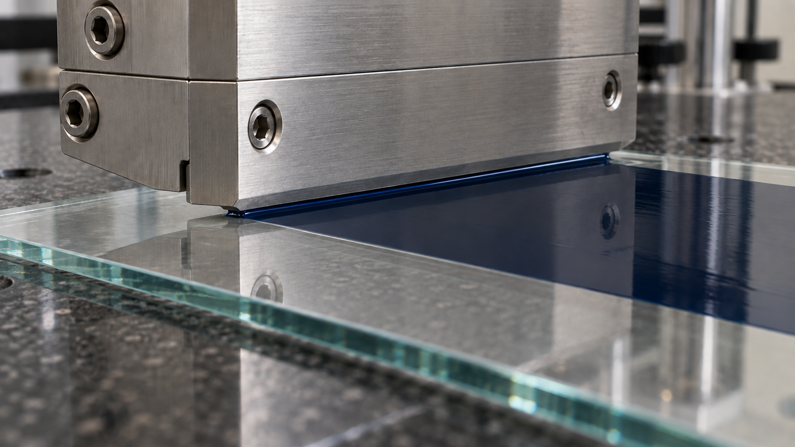
A slot die is a precision-machined head, usually made of two halves clamped together. Liquid enters a distribution cavity, or manifold, which spreads it across the width of the die. It then flows through a narrow slot, whose opening is often set by a thin spacer called a shim, and leaves at the die lips. Below the lips, the liquid bridges the gap to the substrate and forms the coating bead [1].
The bead has two free surfaces. The upstream meniscus sits on the side the substrate approaches from, where the liquid meets the oncoming dry substrate at a moving contact line. The downstream meniscus sits on the side where the coated film leaves the bead. The stability of these two menisci decides whether a uniform film forms. The pressure inside the bead, set by viscous flow through the gap and by capillary pressure at the menisci, must balance so that neither meniscus is pushed out of the gap or drawn too far in [6].
Unlike spin and dip coating, where the film is what the flow leaves behind and its thickness depends on the ink’s properties and on evaporation, slot-die coating is pre-metered: the pump flow rate and the coating speed set it. The film is one-sided, its width is defined by the die and any shim, stripes can be coated with a suitably shimmed die [8], and the same principle works from sheet-to-sheet lab coating to roll-to-roll production [2][9].
In lab slot-die coaters, the die usually moves over a substrate held on a flat stage, or the stage moves under a fixed die. Either way, the coating speed U is the relative speed between the die and the substrate.
3. Pre-metered thickness: h = Q/(W·U)
At steady state, mass conservation means the volume pumped per second equals the volume laid down per second. A film of width W and wet thickness hwet, moving away from the die at speed U, carries a volume W·hwet·U per second. Setting this equal to the flow rate Q gives the pre-metered relation [1][2]:
SI units: Q in m3/s, W in m and U in m/s give hwet in m, because m3/s ÷ (m × m/s) = m.
Lab units: 1 µL = 1 mm3, so Q in µL/s (= mm3/s), W in mm and U in mm/s give hwet in mm. Multiply by 1,000 for µm.
The relation contains no fluid properties: viscosity, surface tension and density decide whether the bead is stable, not the thickness it delivers. Once a stable bead is found, thickness changes predictably with flow rate or speed.
hwet = 5 mm3/s ÷ (50 mm × 10 mm/s) = 5 ÷ 500 mm = 0.01 mm = 10 µm.
If the ink contains a non-volatile volume fraction of 0.02, the dry film is roughly 10 µm × 0.02 ≈ 0.2 µm, or about 200 nm, assuming the dried film is dense and the coated width does not change. Halving Q or doubling U halves both numbers, provided the bead stays inside the coating window. All values are assumed for illustration.
The dry-thickness estimate is approximate, because dried films may be porous or shrink at the edges. In practice, use the relation to set the first run, measure the dry thickness, and calibrate an effective conversion factor for each ink. Thickness measurement is covered in How to Measure Thin Film Thickness: Profilometry, Ellipsometry and Interference.
The same arithmetic gives the ink volume needed. A coated length L uses V = W·L·hwet. In the example above, a 150 mm long coating uses 50 × 150 × 0.01 = 75 mm3, or 75 µL, which is also Q times the coating time of 15 s. The syringe must hold this plus the volume needed to fill the lines and die, prime the bead and run any start-up length, which depends on the die and tubing and, in small lab coatings, is often larger than the coated volume. These setup calculations will be collected in Slot-Die Setup Calculator: Flow Rate, Coating Speed, Gap and Syringe Volume.
4. The coating window
The coating window is the range of operating conditions in which the bead is stable and the film is uniform. It is usually drawn as a map with coating speed (or capillary number) on one axis and wet thickness, often scaled by the gap, on the other. Inside the window, hwet = Q/(W·U) holds. At its boundaries, the bead fails in recognisable ways [3][6]:
| Limit | What happens | Typical trigger | Usual first response |
|---|---|---|---|
| Low-flow limit (minimum wet thickness) | The downstream meniscus is drawn into the gap and the film breaks into rivulets, ribs or stripes | Too little flow for the gap and speed; film too thin | Raise Q, lower U or reduce the gap |
| Air entrainment | The upstream contact line cannot keep up and air is trapped under the film as bubbles or streaks | Speed too high for the liquid and substrate wetting | Lower U; improve wetting; adjust upstream pressure |
| Upstream leaking, weeping or dripping | Liquid escapes past the upstream lip and runs back along the die or drips | Too much flow for the speed, excessive bead vacuum or unsuitable gap/lip geometry | Reduce excess flow or vacuum; reassess the gap |
| Ribbing (downstream) | Regular lines in the coating direction from an unstable downstream meniscus | Operating near the low-flow limit; die-lip geometry | Move away from the limit; check the lips |
General failure modes reported in the slot-die literature and reviews; the boundaries for a particular ink, die and substrate must be found experimentally.
The low-flow limit is the boundary that matters most for thin films. Ruschak analysed the capillary-dominated limit [4]; Higgins and Scriven extended the analysis to include viscous pressure losses within the bead [6]. Later experiments and simulations mapped the minimum wet thickness as a function of capillary number and gap, and showed that the limit also depends on fluid rheology, for example in dilute solutions of high-molecular-weight polymers [7][5][10]. A review by Ding and co-workers summarises the vacuum limits, the low-flow limit, the zero-vacuum wet-thickness limit, dynamic wetting failure and speed limits in one place [3].
5. Gap, capillary number and bead vacuum
Three quantities control where an operating point sits relative to the window.
The gap. The distance between the die lips and the substrate. For a given wet thickness, a smaller gap generally makes the bead easier to sustain at low flow, because the downstream meniscus has less room to be drawn in. A gap that is too small risks contact with the substrate, particles or substrate bow, and increases sensitivity to small height variations. The gap is therefore usually chosen as a small multiple of the target wet thickness, with the exact ratio depending on the capillary number and die geometry [6][7][5]. The flatness and parallelism of the die and stage therefore matter as much as the set-point.
The capillary number. Ca = μU/σ, where μ is viscosity, U speed and σ surface tension. It compares viscous forces with surface tension. In the low-Ca, low-Reynolds-number regime, lowering Ca generally lowers the minimum wet thickness relative to the gap; this trend need not hold when inertia becomes important [5][3].
Bead vacuum. On many slot-die coaters, a slight under-pressure can be applied to the upstream side of the bead through a vacuum box. This stabilises the upstream meniscus and typically widens the window toward thinner films and higher speeds. Too much vacuum draws liquid upstream and causes weeping, so bead vacuum has its own upper and lower limits [6][3]. It acts on the upstream meniscus; in the classic viscocapillary analysis, the downstream low-flow limit itself is set by the gap, the capillary number and the flow rather than by the vacuum. Bead vacuum is a feature of the die set-up, distinct from the vacuum that holds a substrate flat on a stage.
6. Start, stop and edges
The pre-metered relation describes steady state. Real lab coatings are short, so the start and end can be a significant fraction of the coated length.
- Start-up. The bead must form before the substrate moves under it at full speed. Too little liquid at the start gives a thin or missing leading edge; too much gives a thick bulge. A short pre-dispense or a controlled delay before motion are common approaches.
- Stop. When the pump stops, the liquid in the die and lines keeps flowing briefly because of compliance in the tubing, syringe and any trapped air, so the trailing edge is often thick; stopping the pump slightly before the end of travel helps.
- Side edges. The film often has thicker or thinner bands at its side edges, caused by flow at the ends of the slot and by surface tension pulling at the film edge during coating and drying. Schmitt and co-workers investigated these edge effects in stripe and pattern coating of battery electrodes and showed that they depend on the die geometry and process conditions [8].
For thin-film work, it is normal to define a useful area that excludes a margin at each edge and at the start and end, and to place devices or measurements within it.
7. Common slot-die defects
Many slot-die defects can be traced to one of a small number of causes: the bead, the die, the ink, the substrate or the motion [11].
| Defect | Likely causes | Things to check |
|---|---|---|
| Streaks or lines in the coating direction | Particle or dried ink at the lips; damaged lip; ribbing near the low-flow limit | Clean the lips; filter the ink; raise flow or reduce the gap |
| Bands across the coating direction (chatter) | Speed fluctuation, vibration, pump pulsation or gap variation | Mechanical rigidity; pump smoothness; substrate flatness |
| Rivulets or bare stripes | Below the low-flow limit | Raise Q or lower U; reduce the gap |
| Bubbles or air streaks | Air entrainment at high speed; air in the syringe or lines | Lower speed; degas the ink; purge lines |
| Thick or thin side edges | Edge flow at the slot ends; drying-driven edge effects | Die and shim geometry; define a useful area |
| Rough or hazy film | Drying too slow or uncontrolled; crystallisation during drying | Drying conditions; gas quenching or heating where suitable |
Diagnostic guide only; each cause should be confirmed by changing one variable at a time.
8. Slot-die coating at lab scale
Lab slot-die coaters are commonly used for two purposes: making uniform films over areas larger than a spin coater handles comfortably, and developing an ink and process that can later move to roll-to-roll production. Reviews of printed solar cells describe slot-die coating as one of the main scalable methods for this reason [2], and scalable slot-die processes have been reported for perovskite solar cells [9].
Several points differ from large-scale coating:
- Short coatings. A lab coating may be only a few times longer than the start-up and stop transients, so section 6 matters more than it does on a roll.
- Low speeds and thin films. Lab work often uses dilute inks and low speeds to reach thin dry films. At low speeds with volatile solvents, evaporation near the meniscus can start to influence film formation, in a way loosely similar to the capillary regime of dip coating. Such low-speed operation is sometimes grouped with blade and dip coating under the label meniscus-guided coating; how far the pre-metered relation still describes the dry film in this case depends on the ink and conditions and should be checked by measurement.
- Drying is part of the process. The wet film is set by the pump, but the morphology of the dry film is set by how it dries. For many functional inks, especially perovskite precursors, controlled drying such as gas quenching or heating is essential. This is covered in Air-Knife and Gas Quenching for Blade- and Slot-Die-Coated Films.
- Ink transfer. A spin-coating ink usually needs reformulating for slot-die coating; see From Spin Coating to Slot-Die and Blade: Scaling a Thin-Film Ink.
9. Setting up a first run
The sequence below is a general starting point, not a recipe for a particular ink.
- Define the target. Choose the dry thickness, estimate the non-volatile volume fraction of the ink, and convert to a target wet thickness.
- Choose width and speed. The coated width is set by the die and any shim. Choose a moderate speed within the coater’s range.
- Calculate the flow rate. Q = hwet × W × U. In lab units, mm × mm × mm/s gives mm3/s, which equals µL/s. Check that Q lies within the pump’s range.
- Set the gap. Start with a gap that is a small multiple of the wet thickness. Zero the gap on the substrate surface first, so the set value is relative to the actual surface.
- Prepare the substrate. Clean it, hold it flat, and confirm that the ink wets it; plasma surface activation covers wettability and adhesion.
- Prime and coat. Purge air from the syringe and lines, form the bead, then start motion. Watch the bead and both menisci.
- Adjust one variable at a time. If the film breaks into stripes, reduce the gap, raise Q or lower U (raising Q or lowering U also thickens the film, so recheck it against the target); if it entrains air, reduce speed; if it leaks upstream, reduce excess Q or bead vacuum and reassess the gap.
- Measure and calibrate. Measure the dry thickness at several positions, compare with the prediction, and adjust the conversion factor for the next run.
10. What a slot-die coater page tells you
When comparing lab slot-die coaters, look for substrate size, coating-axis speed, pump range, gap control, stage hold-down, and whether the die width, bead vacuum and heating are stated. The table quotes the Levon™ SD200 page; “not stated” means the page does not give the value, not that the feature is absent.
| Specification | SD200 |
|---|---|
| Compatible substrate area | 200 × 200 mm |
| Compatible substrate thickness | 0.05–10 mm |
| Coating platform | 260 × 260 mm granite platform with vacuum adsorption; standard hole size 2 mm (minimum 1 mm, customizable) |
| Tool alignment and vertical drive | Auto tool alignment; dual vertical-axis servo motors, automatic adjustment |
| Z-axis | Speed 0.001–20 mm/s; stroke 0–50 mm; positioning accuracy 0.001 mm; synchronous repeatability ±0.002 mm |
| Y-axis | Speed 0.002–50 mm/s; stroke 0–355 mm; positioning accuracy 0.001 mm |
| Injection pump | Capacity control 0–10 mL; output speed control 0–1000 µL/s |
| Contact detection | Resolution ±1 µm; accuracy 1 µm |
| Utilities | 800 W; AC 200–240 V single-phase (220 V model); gas interface: rear-panel outlet, 6 mm outer diameter |
| Dimensions and weight | 820 × 600 × 680 mm; installation space 920 × 700 × 780 mm; 100 kg |
| Slot-die head width | Not stated |
| Shims or stripe coating | Not stated |
| Bead vacuum | Not stated |
| Heated platform | Not stated |
| Glovebox placement | Not stated |
Specifications as published on the Levon™ SD200 product page on 22 October 2026. The page does not label which axis is the coating axis; the Y-axis, with the longer stroke, is the likely candidate, but confirm this before planning coated lengths. The platform “vacuum adsorption” holds the substrate down; it is not bead vacuum. Because the die width is not stated, the coated width W must be confirmed before calculating Q.
Read against the physics above, the injection pump sets Q, the axis speed sets U, and the Z-axis repeatability and contact detection set and repeat the gap from a zero found on the substrate. With the illustrative numbers from section 3, 5 µL/s lies well within the stated pump range of 0–1000 µL/s, and 10 mm/s within the stated Y-axis range of 0.002–50 mm/s. For a compatible substrate area of 300 × 300 mm, the SD200 page lists the SD300 as a related model; see the Levon™ slot-die coater category page.
11. Keep Exploring the Slot-Die and Blade Coating Knowledge Hub
Start here
- Solution-Processed Thin Films: Choosing Spin, Dip, Slot-Die or Blade Coating — when slot-die coating is the right method, with the interactive coating method selector.
- Spin Coating Explained: Stages, Physics and Film Thickness — the usual starting point for inks that later move to slot-die coating.
Slot-die and blade coating guides
- Slot-Die Setup Calculator: Flow Rate, Coating Speed, Gap and Syringe Volume — the section 3 and 9 arithmetic in one place.
- Doctor Blade Coating: Blade Gap vs Wet Film Thickness — the self-metered alternative with a fixed gap.
- Wire-Bar (Mayer Rod) Coating: Wire Diameter and Wet Film Thickness — wet thickness set by the rod geometry.
- From Spin Coating to Slot-Die and Blade: Scaling a Thin-Film Ink — reformulating and transferring an ink.
- Air-Knife and Gas Quenching for Blade- and Slot-Die-Coated Films — controlling how the wet film dries.
- Perovskite Film Fabrication: Spin Coating, Antisolvent Timing and Annealing — the lab process that slot-die coating often scales up.
Links will be added as each article is published.
Levon™ slot-die coaters
- SD200 Slot-Die Coater — 200 × 200 mm compatible substrate area, 260 × 260 mm granite platform with vacuum adsorption, integrated injection-pump control (0–10 mL, 0–1000 µL/s).
- SD300 Slot-Die Coater — listed on the SD200 page as the related model for a 300 × 300 mm compatible substrate area.
- All Levon™ slot-die coaters — the slot-die coater category page.
Questions about a specific ink, substrate or configuration can be sent through the contact form.
12. FAQ
What is slot die coating?
Slot die coating is a pre-metered method in which a pump feeds ink at a controlled flow rate through a narrow slot in a die, forming a liquid bead in the gap between the die and a moving substrate. Everything pumped is laid down, so the wet thickness is set by the flow rate, the coated width and the speed.
How do I calculate wet film thickness in slot-die coating?
Use hwet = Q/(W·U). With Q in µL/s (equal to mm3/s), W in mm and U in mm/s, the result is in mm. For example, with illustrative values, 5 µL/s over 50 mm at 10 mm/s gives 0.01 mm, or 10 µm wet. Multiply by the non-volatile volume fraction for a rough dry thickness.
What is the coating window?
The coating window is the range of flow rate, speed and gap in which the coating bead is stable and the film is uniform. Its boundaries include the low-flow limit, where the film breaks into stripes; air entrainment at high speed; and leaking or dripping at the upstream side. Outside the window the formula no longer predicts a uniform local thickness.
Why does my slot-die film break into stripes?
Stripes or rivulets usually mean the operating point is below the low-flow limit: the film is too thin for the gap and speed. Increase the flow rate, reduce the speed or reduce the gap. Streaks that stay in one place can also come from particles or dried ink on the die lips.
How does slot-die coating differ from blade coating?
Slot-die coating is pre-metered: the pump sets the thickness. Blade coating is self-metered: the gap under the blade and the ink’s flow behaviour set how much liquid passes, so viscosity and speed affect the thickness. Slot-die coating gives direct thickness control through metered flow, while blade coating is simpler to set up.