
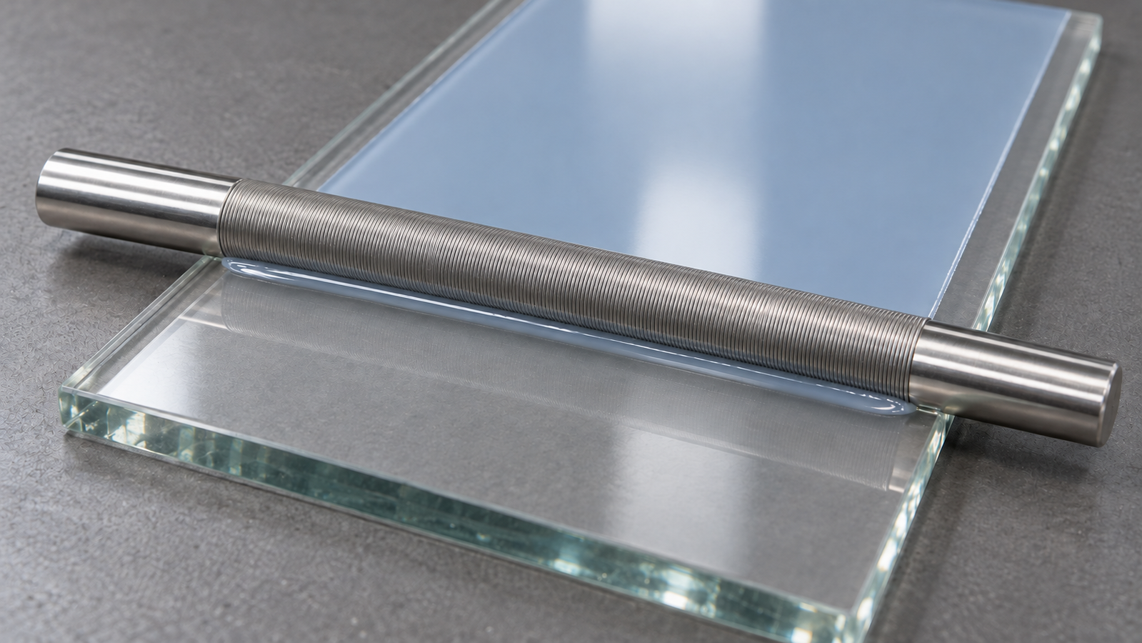
A wire-bar, or Mayer rod, is a metal rod with fine wire wound tightly around it. Drawn across a substrate through a pool of liquid, it leaves a wet film whose thickness is guided mainly by the wire diameter. That makes rod coating one of the most repeatable lab coating methods, and it raises one practical question: what wet film does a given wire give? This guide explains the geometric thickness estimate, about 0.107 times the wire diameter, why actual films differ, and how to choose and calibrate a rod for a target dry thickness.
In one paragraph: the substrate-facing groove between touching round wires has an ideal cross-section of (1/2 − π/8)d2 per wire turn, giving a geometric thickness reference of about 0.1073d, where d is wire diameter. Actual wet thickness also depends on liquid flow, wetting, speed and rod contact; this reference is not a universal upper limit. Use the supplier’s nominal wet thickness to select a rod, then calibrate with a measured film. The ridges left by the wires level under surface tension; at fixed ridge spacing, thicker and lower-viscosity films level faster [3]. Dense dry thickness is roughly wet thickness times the non-volatile volume fraction.
1. The short answer
Mayer rod coating thickness depends on wire geometry and liquid flow. Distinguish the geometric reference from the measured wet film:
| Quantity | Relation | Status |
|---|---|---|
| Substrate-facing groove area per wire turn | (1/2 − π/8)d2 ≈ 0.1073d2 | Ideal geometry for touching round wires on a flat substrate |
| Geometric thickness reference | hgeom ≈ 0.1073d | A reference, not a universal upper limit |
| Calibrated wet film | hwet = k · 0.1073d | k is measured for the ink, rod and conditions; it is not bounded by 1 |
d: wire diameter; k: measured wet thickness divided by the geometric reference. The geometry is derived in section 3; calibration is discussed in section 4.
The dry film is then roughly φ·hwet, where φ is the volume fraction of material left after drying. Because geometry does not determine the exact wet thickness, the reliable way to use a wire-bar is to pick a rod from its supplier’s nominal thickness, coat once, measure, and record the effective ratio of dry thickness to wire diameter for that ink. For where rod coating sits among the solution methods, see the pillar guide to solution-processed thin films, with its interactive coating method selector.
2. How a wire-wound rod meters liquid
A wire-wound rod consists of a straight core, usually stainless steel, with a single wire wound around it in a tight helix so that neighbouring turns touch. The rod is laid across the substrate and moved over it, or the substrate is moved under it, with an excess of liquid in front [2].
The wire turns touch the substrate. Liquid cannot pass under the wire crowns, only through the grooves between them. Each groove is a small channel that runs around the rod, and as the rod advances, each groove carries liquid past the contact line and leaves a stripe of it behind. The closely spaced stripes then flow together into a continuous film.
This distinguishes the rod from a blade. Both meter liquid by drag and pressure through a narrow channel, but a blade’s channel is an adjustable gap, while the rod’s channels are the fixed grooves between its wire turns. The rod sets a fixed channel cross-section: there is no gap to zero, and an undamaged rod gives the same grooves every time. The trade-off is that each rod gives one nominal thickness: changing thickness means changing rods.
Wire-bar coating is classed with blade, dip and roll coating as a self-metered method, in contrast to pre-metered methods such as slot-die coating, where a pump sets the flow [1]. It remains self-metered: groove geometry provides a thickness reference, while liquid properties and operating conditions determine the actual result.
3. Groove geometry and a thickness estimate
Consider a rod with wire diameter d, wound so that neighbouring turns touch. The axial distance between wire centres, the pitch, is then also d. Place the rod on a flat substrate. For the thickness estimate, count the exterior groove between the substrate and the lower semicircles of the wires.
For one pitch, the substrate-facing region is a rectangle of width d and height d/2, minus one semicircle of diameter d. The core-facing cavity is not included. The exterior groove area is:
Spread over one pitch of width d, this volume corresponds to a uniform layer of thickness Agroove/d ≈ 0.1073d. This is a geometric reference for close-wound round wires on a flat substrate, not a universal upper limit or a complete model of liquid flow.
Use the rod supplier’s nominal wet thickness for initial selection and verify it with the intended ink. To express a measured result relative to the geometric reference, define k = hwet/(0.1073d). This empirical calibration factor includes flow and transfer effects; it is not a fraction of a fixed volume and need not be less than 1. In drag-dominated flow with full crown contact on a flat, rigid substrate, k is expected to be below 1, because the liquid in a groove moves more slowly on average than the substrate; values above 1 point to liquid passing under the crowns (a rough or uneven substrate, loose winding, or the rod lifting at speed) or to strong pressure-driven flow.
Several real-world details move the geometry away from this ideal:
- Wire spacing. If the wire is not wound with turns touching, the pitch is larger than d, the open area per pitch grows, and the gap between turns connects the groove to the cavity behind it, so the 0.1073d reference no longer applies. Most metering rods are close-wound, but the geometry should be checked if the thickness is far from the estimate.
- Wire wear and deformation. Abrasive inks and pressure can flatten the crowns of the wires over time, changing the groove area. Damaged or kinked turns leave streaks.
- Substrate compliance. On a soft or flexible substrate, the wires press slightly into the surface and the effective groove is smaller; on a rough substrate, extra liquid passes under the crowns.
- Formed rods. Some metering rods have a profile machined or rolled into a solid rod instead of a wound wire. Their groove shape differs, and the 0.1073d relation does not apply; use the groove volume given for that rod, or calibrate.
4. Flow and transfer: why calibration matters
The geometric estimate does not calculate the liquid velocity through the grooves or the downstream meniscus. Wetting, pressure, viscosity, speed and rod contact can change the deposited thickness. Liquid left on the rod matters at the start and end of a stroke, but a laboratory drawdown rod need not rotate, and for a rod that does not rotate, steady coating does not divide the groove liquid between rod and substrate. No universal film-split fraction can be inferred from the groove area.
Write the measured ratio to the geometric reference as a calibration factor k. The wet film is then hwet = k·0.1073d. The value of k depends on:
- Wetting. Wetting of the substrate and the wires sets the shape of the menisci where liquid leaves the grooves, and whether the stripes from neighbouring grooves merge into a continuous film. A liquid that wets the substrate poorly can neck in, bead up or dewet, giving a thinner or patchy film.
- Viscosity and speed. Viscous and capillary forces affect flow through the grooves and the downstream meniscus, so k can change with speed and viscosity.
- How full the grooves are. If too little liquid is placed in front of the rod, the grooves do not fill and the film becomes thin or patchy whatever k would otherwise be.
- Rheology. Shear-thinning and viscoelastic inks flow differently from simple liquids, and viscoelastic inks can form filaments that leave a ribbed surface.
Because these effects cannot be predicted reliably for a new formulation, k is best treated as an empirical constant. Coat once with a rod chosen from its supplier’s nominal wet thickness, measure the wet or dry thickness, and compute k = hwet/(0.1073d), or the equivalent dry ratio. For the same ink, rod and speed it is usually reproducible.
Why rod catalogues quote wet thickness. Suppliers of wire-wound rods commonly list a nominal wet film thickness for each rod, rather than only a wire diameter. That value may be based on geometry or a reference test, and numbering conventions differ between suppliers, so check how each supplier defines its figures.
5. Ridges and levelling
Right behind the rod, each groove leaves its own stripe, so the surface has ridges spaced at the wire pitch, which for close-wound wire is d. Surface tension pulls the ridges flat; viscosity resists.
Orchard analysed the levelling of a sinusoidal ripple on a thin liquid film [3]. For a Newtonian film, the time for the ripple amplitude to decay scales as:
μ: viscosity; λ: ripple wavelength (here about the wire diameter); σ: surface tension; h: mean film thickness. The strong dependence on λ and h is the useful part.
Three consequences follow for rod coating:
- Fine wires level fast. Halving the wire diameter halves the ridge spacing, which shortens the levelling time by a factor of 16 if the film thickness stayed the same. If film thickness also halves while viscosity and surface tension remain unchanged, that offsets the gain by a factor of 8, leaving about a factor of 2 overall.
- Drying competes with levelling. As solvent evaporates, viscosity rises and the film thins; both slow levelling sharply. If the film dries before it levels, the ridges are frozen in as a striped surface. Fast-drying inks and heated substrates make this more likely.
- Thicker, lower-viscosity films level best. Low viscosity at the moment of coating and enough time before the film sets are what remove the ridges.
Ridges that remain visible after drying are a classic rod-coating defect. Streaks from a damaged wire or a particle appear as isolated lines rather than a regular pattern; coating defects in general are treated in depth by Gutoff and Cohen [4].
6. Speed, viscosity and pressure
The grooves give a wire-bar a repeatable geometry, but they do not fix the flow rate or make coating insensitive to speed and viscosity:
- Speed. At very low speed, the stripes can start to dry, or the liquid can retract on a poorly wetted substrate, before they merge and level. At high speed, a viscous liquid may not keep the groove inlets fully flooded from the bead in front of the rod, and the flow at the downstream meniscus can change. A middle range of speeds often gives the most reproducible film.
- Viscosity. Low-viscosity liquids fill grooves easily and level quickly, but can also run or dewet before drying. High-viscosity liquids may leave ribs and need slower speeds or fine wires.
- Pressure on the rod. The rod should rest evenly on the substrate. Pressing too hard deforms soft substrates and wears wires; too little contact, or a substrate that is not flat, lets liquid pass under the crowns and thickens the film locally.
- Liquid pool. The bead of liquid in front of the rod should be enough to fill every groove for the whole coating length. Running out partway gives a film that thins towards the end.
These effects mean that the calibration factor measured at one speed should be checked if the speed changes substantially. A motorised drive controls the coating speed and reduces manual speed variation; rod contact and loading still need to be checked.
7. Wire diameter vs wet and dry thickness
The table gives illustrative wet films using hwet = 0.1073kd with k = 1, plus dry films at two volume fractions. These are geometric estimates, not measured results or guaranteed rod outputs.
| Wire diameter d | Illustrative wet film, k = 1 | Dry film at φ = 0.02 | Dry film at φ = 0.20 |
|---|---|---|---|
| 0.05 mm | about 5.4 µm | about 0.11 µm | about 1.1 µm |
| 0.08 mm | about 8.6 µm | about 0.17 µm | about 1.7 µm |
| 0.10 mm | about 10.7 µm | about 0.21 µm | about 2.1 µm |
| 0.20 mm | about 21.5 µm | about 0.43 µm | about 4.3 µm |
| 0.30 mm | about 32 µm | about 0.64 µm | about 6.4 µm |
| 0.50 mm | about 54 µm | about 1.1 µm | about 11 µm |
Calculated as hgeom = (1/2 − π/8)d, hwet = k·hgeom with k = 1 assumed, and hdry = φ·hwet for a dense dried film. The wire diameters are examples of the range in common use, not a list of available rods. Calibrate with a measured film.
Two points stand out. First, the thinnest practical wet films from a wire-bar are several micrometres, because wire finer than a few hundredths of a millimetre is fragile. Very thin dry films therefore come from dilute inks. Second, thickness changes in steps from rod to rod; to fine-tune between rods, adjust the ink concentration. Thickness measurement methods are compared in How to Measure Thin Film Thickness: Profilometry, Ellipsometry and Interference.
8. Rod, blade or slot-die?
Rod, blade and slot-die coating all produce a film on a flat substrate in one stroke. The choice comes down to how the thickness is set.
| Aspect | Wire-bar (Mayer rod) | Doctor blade | Slot-die |
|---|---|---|---|
| What sets wet thickness | Groove geometry, liquid flow and coating conditions | Blade gap, plus pressure flow, rheology and speed | Pump flow rate, coating width and speed |
| First estimate | Supplier’s nominal wet thickness; verify with the intended ink | About half the gap; calibrate the ratio | Q/(W·U), independent of viscosity within the coating window |
| Adjusting thickness | Change rod (steps) or ink concentration | Change gap continuously | Change flow rate or speed continuously |
| Set-up effort | Very low; no gap to zero | Low; zero and set the gap | Higher; priming, gap and coating window |
| Typical surface artefact | Ridges at the wire pitch if levelling is slow | Streaks from particles or a nicked edge | Edge beads, ribbing outside the window |
General comparison. Each method has exceptions depending on ink, substrate and set-up.
The rod’s main advantage is repeatability with little set-up: one rod always gives the same groove geometry. Its main limitation is that thickness comes in steps. A blade, by contrast, gives a continuously adjustable gap but a thickness that depends more on the ink’s flow, as explained in Doctor Blade Coating: Blade Gap vs Wet Film Thickness. When an ink is moving from spin coating to a larger-area method, the rod is often the quickest first test of whether the ink forms a good film at all; the wider transfer problem is covered in From Spin Coating to Slot-Die and Blade: Scaling a Thin-Film Ink.
Where rod coating is used. Rod coating has been used to make transparent electrodes from silver nanowire inks on flexible substrates [5] and from carbon nanotube inks [6], where a rod spreads a dilute dispersion into a thin, even network. Perovskite absorber layers have also been reported using a wire-coil bar [7] and, separately, D-bar coating with a modified precursor solution [8]. In each case the authors’ ink formulation and drying conditions mattered as much as the rod; the results apply to their conditions.
9. Setting up a rod coating
A practical sequence for a first coating on a motorised film applicator fitted with a wire rod, with all numbers to be adapted to the ink:
- Estimate the wet thickness. From the target dry thickness and an estimated φ, hwet = hdry/φ. Choose a rod with a supplier-listed nominal wet thickness near this target, then calibrate it with the intended ink.
- Prepare the substrate. Clean it and hold it flat on a vacuum panel. The film must wet the substrate; a liquid that dewets will retract into droplets whatever the rod.
- Check the rod. Inspect the wire for kinks, gaps between turns or dried residue. Clean the rod immediately after use, because dried ink in the grooves reduces the groove volume.
- Dispense the liquid. Place a line of liquid in front of the rod across the coating width, enough to fill the grooves for the full length plus a margin. Estimate it from width × length × hwet, then add the liquid left on the rod.
- Coat at a steady speed. Start in the middle of the useful speed range. Keep the rod pressure even across its length.
- Let it level, then dry. Give the ridges time to flatten before heating or blowing gas across the film, unless the process needs fast drying. A heated panel and an air knife both shorten the time available for levelling.
- Measure and correct. Measure the dry thickness at several points away from the start and end. Calculate the effective calibration factor or dry-to-wire ratio. Change the rod for large corrections and the ink concentration for small ones.
Common problems. A regular striped pattern at the wire spacing means the film dried before it levelled: use a finer rod, lower the viscosity, or slow the drying. Isolated streaks point to a damaged wire or a particle in the ink. A film that thins towards the end means the liquid line ran out. Patchy coverage suggests poor wetting or too little liquid to fill the grooves.
10. Levon™ film applicators with a wire rod
The table quotes the Levon™ PF200-H and PF400 / PF400-H product pages, which both list a wire rod among the coating tools. “Not stated” means the page does not give the value, not that the feature is absent.
| Specification | PF200-H | PF400 / PF400-H |
|---|---|---|
| Coating tools | Can be equipped with an adjustable film scraper, a four-sided coater and a wire rod | Adjustable film scraper or standard wire rod operation |
| Coating speed | 1–50 mm/s | 1–300 mm/s |
| Speed regulation accuracy | 1 mm/s | 1 mm/s |
| Stroke length | 250 mm | 420 mm maximum |
| Vacuum panel | 380 × 210 mm, hard-anodized aluminum, mirror-polished; A4 adsorption area | 540 × 345 mm, hard-anodized, flat surface; A4/A3 adsorption area, optional |
| Heated panel | RT to 200 °C; heating rate 1–10 °C/min; thermal uniformity ≤±1.5% | PF400-H: RT to 200 °C; ±0.5 °C control accuracy; thermal uniformity ≤±4%; linear heating-rate adjustment. PF400: heating not stated |
| Air knife configuration | Angle −45° to 45°; height 10–35 mm above the substrate; modules with knife lengths of 80–200 mm | Modules with knife lengths of 150–320 mm |
| Control | 4.3-inch touchscreen HMI; 100 recipes, 5 steps per recipe | 7-inch touchscreen; PF400 with PLC control |
| Wire diameters or rod sizes supplied | Not stated | Not stated |
| Rod length or coating width | Not stated | Not stated |
| Glovebox operation | Not stated | Not stated |
Specifications as published on the Levon™ PF200-H and PF400 product pages on 22 October 2026. The pages do not list wire diameters, rod sizes or coating widths for the wire rod; these depend on the tool supplied and are confirmed at quotation.
How this connects to the guide: a motorised drive reduces manual variation in coating speed (section 6), the vacuum panel helps hold the substrate flat under the wires (section 3), and a heated panel and air knife, where fitted, control drying, which competes with levelling (section 5).
11. Keep Exploring the Slot-Die and Blade Coating Knowledge Hub
Start here
- Solution-Processed Thin Films: Choosing Spin, Dip, Slot-Die or Blade Coating — where rod coating fits, with the interactive coating method selector.
- Spin Coating Explained: Stages, Physics and Film Thickness — the usual starting point for inks that later move to rod or blade coating.
- Silver Nanowire Transparent Conductive Films - University of Central Florida, 2021 — a research summary on even silver nanowire networks for transparent electrodes, made by drop-casting and spin coating rather than with a rod; useful background on what makes such networks uniform.
Slot-die and blade coating guides
- Doctor Blade Coating: Blade Gap vs Wet Film Thickness — the gap-metered alternative.
- Slot-Die Coating Explained: Pre-Metered Thickness and the Coating Window — the pump-metered alternative.
- From Spin Coating to Slot-Die and Blade: Scaling a Thin-Film Ink — reformulating and transferring an ink.
- Air-Knife and Gas Quenching for Blade- and Slot-Die-Coated Films — controlling how the wet film dries.
Links will be added as each article is published.
Levon™ film applicators
- PF200-H Heated Film Applicator — 1–50 mm/s over a 250 mm stroke; can be equipped with a wire rod.
- PF400 Film Applicator (PF400 and PF400-H) — 1–300 mm/s, 420 mm maximum stroke; film scraper or standard wire rod operation.
- All Levon™ film applicators — the film applicator category page.
Questions about a specific ink, substrate or rod can be sent through the contact form.
12. FAQ
How thick is the wet film from a Mayer rod?
For close-wound round wire of diameter d, the substrate-facing groove geometry gives a thickness reference of about 0.1073d. Actual thickness depends on the ink and coating conditions. Start with the supplier’s nominal wet thickness and verify it by measurement.
How do I choose a wire diameter for a target dry thickness?
Divide the target dry thickness by the non-volatile volume fraction to estimate the required wet thickness. Select a rod with a supplier-listed nominal wet thickness near that value, then measure and calibrate it with the intended ink and coating conditions.
Why does my rod-coated film have stripes?
A regular pattern at the wire spacing means the ridges left by the grooves dried before they levelled. Finer wire, lower viscosity, a thicker wet film or slower drying all help. Isolated streaks usually come from a damaged wire or a particle.
What is the difference between a Mayer rod and a doctor blade?
A Mayer rod meters liquid through the fixed grooves between wire turns and rests on the substrate, so each rod gives one nominal thickness. A doctor blade sets an adjustable gap above the substrate, and its thickness depends more on the ink’s flow.
Can I coat perovskite or nanowire inks with a wire-bar?
Both have been reported in the literature: silver nanowire and carbon nanotube transparent electrodes, and perovskite absorber layers. In each case the ink formulation and drying conditions were adapted to the method, so results depend on the authors’ conditions.