
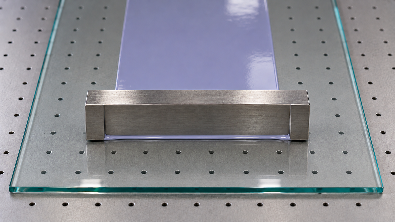
Doctor blade coating spreads a liquid into a film by drawing a straight edge over a substrate at a set gap. It is one of the simplest coating methods in the lab, and it raises one question more than any other: how does the blade gap relate to the wet film thickness? The short answer is that, for a simple liquid at moderate speed, the wet film is roughly half the gap. This guide explains where that rule comes from, when it fails, how pressure flow, rheology and coating speed change it, and how to set a film applicator for a target dry thickness.
In one paragraph: if the liquid is dragged through the gap only by the moving surface (simple shear, or Couette, flow), the average velocity in the gap is half the surface speed and the wet film is about half the blade gap: hwet ≈ g/2. A liquid reservoir in front of the blade adds pressure-driven flow, which thickens the film by a factor of 1 + g2Δp/(6μUL); this term matters most for low-viscosity liquids, slow speeds and a high reservoir [3]. Shear-thinning and blade shape alter it further [4][5]. In meniscus-guided coating, dry film thickness depends on speed: it falls with speed at low speed, where evaporation at the meniscus dominates, and rises with speed at high speed, where viscous drag dominates [6][7]. For films that dry after deposition, dense dry thickness is roughly wet thickness times the wet film’s non-volatile volume fraction.
1. The short answer
The doctor blade coating thickness you get depends on which of three situations you are in:
| Situation | What sets film thickness | Approximate relation |
|---|---|---|
| Liquid dragged through the gap by the moving surface, no significant pressure from a pool upstream of the blade | Gap | hwet ≈ g/2 |
| Liquid reservoir upstream of the blade pushes extra liquid through the gap (tape casting) | Gap, reservoir pressure, viscosity, speed, blade land length | hwet ≈ (g/2)·[1 + g2Δp/(6μUL)] |
| Blade drags a small meniscus of dilute ink; gap large compared with the film (meniscus-guided coating) | Speed, evaporation, viscosity, surface tension, concentration; at high speed also the gap, through the size of the meniscus | Low speed: hdry ∝ 1/U; high speed: hdry ∝ U2/3 |
g: blade gap; U: coating speed; μ: viscosity; Δp: pressure difference across the blade land; L: blade land length in the coating direction. The first two rows follow the flow model analysed for tape casting [3]; the third follows the meniscus-guided coating literature [6][7].
For a dense layer dried after deposition, hdry ≈ φ·hwet, where φ is the wet film’s non-volatile volume fraction. The low-speed meniscus relation instead describes dry material deposited during evaporation. Which row applies is a matter of set-up: a viscous paste spread from a pool in front of a blade behaves like row one or two, while a few microlitres of dilute ink swept by a blade held well above the substrate behaves like row three. For context on where blade coating sits among the solution methods, see the pillar guide to solution-processed thin films, with its interactive coating method selector.
2. How a blade meters liquid
Coating methods are often grouped by how they meter liquid. In a pre-metered method such as slot-die coating, a pump delivers a set volume per second and the average film thickness follows from Q/(W·U), independent of viscosity as long as the coating stays inside its stable coating window. In a self-metered method such as blade, wire-bar or dip coating, the liquid’s own flow decides how much is carried away [1]. For blade coating, that flow happens in the narrow gap between the blade edge and the substrate.
Consider the gap from the blade’s point of view. The blade is stationary and the substrate moves underneath at speed U. Liquid in contact with the substrate moves at U; liquid in contact with the blade does not move. If nothing else drives the liquid, the velocity varies linearly across the gap, from U at the substrate to zero at the blade. This is simple shear, or Couette, flow. In most lab film applicators the blade moves over a fixed substrate instead, but only the relative motion matters.
A second contribution comes from pressure. If a pool of liquid stands in front of the blade, its hydrostatic pressure pushes liquid through the gap in addition to the drag. The pressure-driven, or Poiseuille, flow adds a parabolic velocity profile on top of the linear one. In tape casting, where a reservoir of slurry sits upstream of the blade, this contribution can be significant [3][4].
Downstream of the blade, the film moves with the substrate as a layer of uniform thickness. Volume conservation then gives the wet thickness: the flow per unit width through the gap, q, equals the film thickness times the substrate speed, so hwet = q/U.
3. The half-gap rule
For pure drag flow, the average velocity across a linear profile from U to zero is U/2. The flow per unit width through a gap g is therefore:
For a Newtonian liquid with no pressure gradient under the blade, the wet film is half the gap, independent of speed and viscosity [3].
The half-gap rule is widely used as a starting estimate for lab film applicators, and for a simple liquid at moderate speed it is a reasonable first guess. Measured wet films commonly differ from it, however, for several reasons that the next sections cover:
- Pressure from a liquid pool in front of the blade adds flow and thickens the film.
- Shear-thinning changes pressure-driven flow and can alter the gap-to-thickness ratio [4].
- The blade edge geometry, including its land length and any bevel, changes the flow under the blade [5].
- At small gaps, the real gap may differ from the nominal setting because of substrate flatness, blade deflection, or particles in the ink.
- Capillary pressure at the liquid menisci in front of and behind the blade also creates a pressure difference under the blade, even without a deep pool; it matters most for low-viscosity inks at low speed.
- Right after the blade the film can relax, spread or neck in at the edges, and evaporation starts immediately.
The working rule is to calculate with g/2 for the first coating, measure the dry thickness, and back-calculate an effective ratio of wet thickness to gap for that ink, blade and speed.
4. Pressure flow and tape casting
When liquid is pushed through the gap by a pressure difference Δp across a blade with land length L (the length of the flat underside of the blade in the coating direction), the pressure-driven flow per unit width between two plates is g3Δp/(12μL). Adding it to the drag flow gives:
This drag-plus-pressure model for a Newtonian liquid was analysed for ceramic tape casting by Chou and co-workers [3]. For a reservoir of height H and density ρ, Δp ≈ ρ·g0·H, where g0 is the acceleration due to gravity.
The bracketed correction grows with the square of the gap and with the reservoir pressure, and falls with viscosity, speed and land length. That explains several practical observations: low-viscosity liquids coated slowly from a deep pool come out thicker than the half-gap rule predicts, and a thick, viscous slurry at normal speed follows the rule more closely.
| Case (illustrative) | μ | U | Correction g2Δp/(6μUL) | hwet for g = 200 µm |
|---|---|---|---|---|
| Viscous slurry, normal speed | 1 Pa·s | 10 mm/s | 0.02 | about 102 µm |
| Viscous slurry, slow | 1 Pa·s | 1 mm/s | 0.20 | about 120 µm |
| Thinner ink, normal speed | 0.1 Pa·s | 10 mm/s | 0.20 | about 120 µm |
| Thinner ink, slow | 0.1 Pa·s | 1 mm/s | about 2.0 | about 300 µm (pressure-dominated) |
Assumed values: reservoir height 10 mm, density 1,500 kg/m3 (Δp ≈ 147 Pa), land length 5 mm, Newtonian liquid. Correction = (2 × 10⁻⁴ m)2 × 147 Pa ÷ (6 × μ × U × 0.005 m). Illustrative arithmetic only.
The last row predicts a film thicker than the gap because pressure-driven flow exceeds the drag contribution. This is not, by itself, evidence of model breakdown. If the reservoir level falls during coating, the pressure and thickness also change, so a constant-pressure estimate no longer describes the full run. For low-viscosity inks, reducing the pool height or increasing the speed reduces the pressure contribution.
Wet to dry in tape casting. Ceramic and electrode slurries carry a high solids fraction plus binder, so the dry tape is a sizeable fraction of the wet thickness. The same estimate applies: hdry ≈ φ·hwet/(1 − P), with P the porosity of the dried layer. Drying shrinkage happens mainly through the thickness when the film stays pinned to the substrate.
5. Rheology and blade shape
Many blade-coated liquids are not Newtonian. Pastes, slurries and concentrated polymer or nanoparticle inks usually shear-thin: their viscosity falls at the high shear rates found under the blade. For drag flow alone, the shear rate under the blade is roughly U/g; for U = 10 mm/s and g = 100 µm that is about 100 s−1. The viscosity that matters is the one at this shear rate, not the low-shear value on a data sheet.
Shear-thinning changes pressure-driven flow, so the Newtonian pressure correction need not apply. With homogeneous rheology, no wall slip and no pressure gradient, however, the Couette velocity profile remains linear and the flow remains U·g/2. Power-law tape-casting models treat the combined flow without assuming Newtonian superposition [4]. Viscoelastic liquids may also swell as they leave the gap.
The blade itself matters too. A blade with a long flat land, a short land or a bevelled edge gives different pressure distributions under the blade. Analytical, numerical and experimental comparisons of blade shapes in tape casting show that blade geometry changes the resulting tape thickness, which is one reason a gap-to-thickness ratio measured with one blade does not transfer exactly to another [5].
Practical consequence. Treat the half-gap rule and the pressure correction as guides to the direction of change. For a new ink, calibrate the ratio of wet (or dry) thickness to gap at the speed you intend to use, with the blade you intend to use, and repeat the calibration when the ink formulation changes.
6. Speed regimes in meniscus-guided blade coating
A different situation arises when a small amount of dilute ink is held between a blade and the substrate, and the blade is moved with a gap much larger than the final film. The blade no longer meters the liquid through a narrow channel; it drags a meniscus across the substrate, and the film forms at the contact line at the back of that meniscus. This meniscus-guided blade coating is widely used in the lab for organic semiconductors and perovskites [6][8][9].
In this mode, the gap is not the main control. The dry film thickness depends on the coating speed and shows two regimes, similar to those found in dip coating [6][7]:
- Evaporative (capillary) regime, low speed. Evaporation and solute deposition occur at the meniscus while the substrate passes beneath it. The amount deposited per unit area falls as the speed rises: thickness scales roughly as 1/U. Crystallisation at the contact line in this regime can give aligned domains [8].
- Landau–Levich (draining) regime, high speed. The substrate drags out a liquid film that dries afterwards. Its thickness rises with speed, roughly as U2/3 for a Newtonian liquid, as in the Landau–Levich law for dip coating.
Between the two there is a speed at which the film is thinnest. The regimes and their scaling are explained for dip coating in The Landau-Levich Equation in Practice: Viscosity, Surface Tension and Speed, and the same physics applies at a blade meniscus.
Doctor-bladed perovskite layers illustrate how much the drying conditions matter. Scalable fabrication of efficient perovskite solar cells with doctor-bladed active layers has been reported [9], and the film quality in such work depends strongly on how the wet film dries. Drying control by gas flow is covered in Air-Knife and Gas Quenching for Blade- and Slot-Die-Coated Films.
7. Blade gap vs wet and dry thickness
The table applies the half-gap rule to a range of gaps and two illustrative volume fractions: a dilute functional ink and a concentrated slurry. It is a starting point for the first coating, not a prediction for any particular ink.
| Blade gap | Wet film, half-gap estimate | Dry film at φ = 0.05 | Dry film at φ = 0.30 |
|---|---|---|---|
| 25 µm | about 12.5 µm | about 0.6 µm | about 3.8 µm |
| 50 µm | about 25 µm | about 1.3 µm | about 7.5 µm |
| 100 µm | about 50 µm | about 2.5 µm | about 15 µm |
| 200 µm | about 100 µm | about 5 µm | about 30 µm |
| 400 µm | about 200 µm | about 10 µm | about 60 µm |
Calculated as hwet = g/2 and hdry = φ·hwet for a dense dried film. Pressure flow, shear-thinning, blade shape and evaporation all shift the real values; calibrate with a measured film.
Two observations follow. First, sub-micrometre dry films from a dilute ink need gaps of a few tens of micrometres, where substrate flatness, blade straightness and dust become significant compared with the gap. Second, for very thin films the meniscus-guided mode of section 6 is often more practical than a tiny gap, because it sets thickness through speed and evaporation rather than through a narrow channel. Thickness measurement methods are compared in How to Measure Thin Film Thickness: Profilometry, Ellipsometry and Interference.
8. Film applicator types
In the lab, “doctor blade” covers several tools that set the gap in different ways. The choice affects how finely the gap can be adjusted and how repeatable it is from run to run.
| Tool | How the gap is set | Strengths | Watch for |
|---|---|---|---|
| Adjustable film applicator (film scraper) | Micrometer adjustment at each end of the blade | Continuous choice of gap; one tool covers many thicknesses | Both ends must be set equally; check parallelism and re-zero after cleaning |
| Four-sided (cube) applicator | Fixed, machined clearances, one on each side | Very repeatable; quick to switch between four gaps | Only the machined gaps are available |
| Wire-wound rod | Wire diameter and groove geometry give a reference wet thickness; there is no gap to set | Simple, repeatable, easy to clean | Thickness guided by the rod, not a gap, and still calibrated with the ink; covered separately |
General descriptions of tool types. Available gap values and coating widths depend on the specific tool and are not covered here.
Wire-bar coating meters liquid differently from a blade: the liquid is carried in the grooves between the wire turns, and the wet thickness is guided mainly by the wire diameter rather than by a gap, then calibrated with the ink. It is covered in Wire-Bar (Mayer Rod) Coating: Wire Diameter and Wet Film Thickness.
Blade versus slot-die. A slot die sets the thickness with a pump and uses ink efficiently, but needs priming volume and has a coating window to find. A blade needs only a few drops of ink beyond the film itself and almost no set-up, but the thickness depends on the ink’s flow and needs calibration. The pre-metered alternative and its formulas are described in Slot-Die Coating Explained: Pre-Metered Thickness and the Coating Window and Slot-Die Setup Calculator: Flow Rate, Coating Speed, Gap and Syringe Volume. Moving an ink from spin coating to blade or slot-die coating is covered in From Spin Coating to Slot-Die and Blade: Scaling a Thin-Film Ink.
9. Setting up a lab blade coating
A practical sequence for a first coating on a motorised film applicator, with all numbers to be adapted to the ink:
- Estimate the wet thickness. From the target dry thickness and an estimated φ, hwet = hdry/φ. Start with a gap of 2 × hwet.
- Prepare the substrate. Clean it, and hold it flat on a vacuum panel. Wetting matters: a liquid that dewets will pull back from the edges or break up whatever the gap.
- Zero and set the blade. Zero an adjustable applicator on the substrate surface, or on a reference surface of the same height, then set the gap. For small gaps, check both ends.
- Dispense the liquid. Place a line of liquid in front of the blade across the coating width, enough for the full length plus a margin. Estimate the volume from width × length × hwet and add the liquid that stays on the blade.
- Coat at a steady speed. Choose a speed in the middle of the useful range for the first run. A motorised drive keeps the speed constant along the stroke, which matters when pressure flow or meniscus-guided behaviour makes thickness depend on speed.
- Control drying. A heated panel speeds evaporation and can change film morphology; an air knife can dry or quench the wet film. Keep the drying conditions fixed while calibrating thickness.
- Measure and correct. Measure dry thickness at several points, away from the start and end of the coating. Calculate the effective ratio of dry thickness to gap and scale the gap or speed for the next run.
Common problems. Streaks along the coating direction usually come from particles or dried ink caught under the blade, or from a nicked edge. Thickness that drifts along the coating points to a draining pool or a changing speed. Ridges at the start and end come from the liquid line and the blade stopping. Thick edges and a thinner centre can come from edge effects and drying; exclude the edges from measurements.
10. Levon™ film applicators
The table quotes the Levon™ PF200-H and PF400 / PF400-H product pages. “Not stated” means the page does not give the value, not that the feature is absent.
| Specification | PF200-H | PF400 / PF400-H |
|---|---|---|
| Coating speed | 1–50 mm/s | 1–300 mm/s |
| Speed regulation accuracy | 1 mm/s | 1 mm/s |
| Stroke length | 250 mm | 420 mm maximum |
| Vacuum panel | 380 × 210 mm, hard-anodized aluminum, mirror-polished; A4 adsorption area | 540 × 345 mm, hard-anodized, flat surface; A4/A3 adsorption area, optional |
| Heated panel | RT to 200 °C; heating rate 1–10 °C/min; thermal uniformity ≤±1.5% | PF400-H: RT to 200 °C; ±0.5 °C control accuracy; thermal uniformity ≤±4%; linear heating-rate adjustment. PF400: heating not stated |
| Coating tools | Can be equipped with an adjustable film scraper, a four-sided coater and a wire rod | Adjustable film scraper or standard wire rod operation |
| Control | 4.3-inch touchscreen HMI; 100 recipes, 5 steps per recipe | 7-inch touchscreen; PF400 with PLC control |
| Air knife configuration | Angle −45° to 45°; height 10–35 mm above the substrate; modules with knife lengths of 80–200 mm | Modules with knife lengths of 150–320 mm |
| Vacuum input | 0.06–0.09 MPa, flow more than 15 L/min; 6 mm outer-diameter outlet | 0.06–0.09 MPa; 6 mm outer-diameter outlet |
| Power | AC 200–240 V, single-phase, 50 Hz, 2.0 kW | PF400: 0.4 kW; PF400-H: 2.75 kW |
| Blade gap range | Not stated | Not stated |
| Coating width | Not stated | Not stated |
| Glovebox operation | Not stated | Not stated |
Specifications as published on the Levon™ PF200-H and PF400 product pages on 22 October 2026. Gap range and coating width depend on the coating tool fitted and are not given on the pages. The supplied configuration, including coating tools and any air knife, is confirmed at quotation.
How this connects to the guide: the speed range sets how much of the speed-dependent behaviour in sections 4 and 6 can be explored, the heated panel controls evaporation, and the vacuum panel holds the substrate flat, which matters most at small gaps.
11. Keep Exploring the Slot-Die and Blade Coating Knowledge Hub
Start here
- Solution-Processed Thin Films: Choosing Spin, Dip, Slot-Die or Blade Coating — when blade coating is the right method, with the interactive coating method selector.
- Spin Coating Explained: Stages, Physics and Film Thickness — the usual starting point for inks that later move to blade coating.
Slot-die and blade coating guides
- Slot-Die Coating Explained: Pre-Metered Thickness and the Coating Window — the pre-metered alternative.
- Wire-Bar (Mayer Rod) Coating: Wire Diameter and Wet Film Thickness — wet thickness guided by the rod geometry and calibrated with the ink.
- From Spin Coating to Slot-Die and Blade: Scaling a Thin-Film Ink — reformulating and transferring an ink.
- Air-Knife and Gas Quenching for Blade- and Slot-Die-Coated Films — controlling how the wet film dries.
- The Landau-Levich Equation in Practice: Viscosity, Surface Tension and Speed — the speed law behind the high-speed regime.
Links will be added as each article is published.
Levon™ film applicators
- PF200-H Heated Film Applicator — 1–50 mm/s over a 250 mm stroke, 380 × 210 mm heated vacuum panel (RT to 200 °C).
- PF400 Film Applicator (PF400 and PF400-H) — 1–300 mm/s, 420 mm maximum stroke, 540 × 345 mm vacuum panel; heated panel on the PF400-H.
- All Levon™ film applicators — the film applicator category page.
Questions about a specific ink, substrate or configuration can be sent through the contact form.
12. FAQ
How thick is the wet film compared with the blade gap?
For a Newtonian liquid dragged through the gap with no pressure pushing it, the wet film is about half the gap. Pressure from a liquid pool in front of the blade, shear-thinning (through that pressure-driven flow), blade shape and evaporation all shift the ratio, so calibrate it with a measured film for each ink.
How do I choose the blade gap for a target dry thickness?
Divide the target dry thickness by the non-volatile volume fraction of the ink to get the wet thickness, then double it for the starting gap. Measure the dry film, calculate the effective ratio of dry thickness to gap, and scale the gap for the next coating.
Does coating speed change the thickness in blade coating?
Under the simple half-gap rule, no. With a liquid pool in front of the blade, slower coating lets more pressure-driven flow through and thickens the film. In meniscus-guided coating with a large gap, speed is the main control: dry thickness falls with speed at low speed and rises with speed at high speed.
What is the difference between doctor blade coating and tape casting?
They are the same physical process. Tape casting usually refers to spreading a ceramic or electrode slurry from a reservoir into a thick, flexible tape, where pressure flow from the reservoir matters. Doctor blade coating in the lab often refers to thinner films from small amounts of ink.
Is blade coating better than slot-die coating?
Neither is better in general. Blade coating is simpler, needs little ink and almost no set-up, but its thickness depends on the ink’s flow and must be calibrated. Slot-die coating sets thickness with a pump and is more predictable once the coating window is found, but it needs priming volume and more set-up.