
The number on a laboratory press looks like a fact: 8.0 t, or 16 MPa on the dial. It is the end of a chain. Oil pressure moves a gauge, the reading is converted to force through the area of the piston, and the force is spread over the area of the die. Each link adds something. Resolution says how finely the chain can be read, accuracy how close the reading is to the true force, and repeatability how closely two readings of the same force agree. A force check against a reference load cell measures the chain up to the force on the platens. This guide explains each term, what the PressPro™ specifications print and what they do not, and how a laboratory checks its own press.
In one paragraph: reading a number to more digits does not bring it closer to the true force. Gauge accuracy classes are usually a percentage of the whole scale, so a fixed error band becomes a larger share of the reading at the bottom of the range. A hydraulic press adds friction and a difference between rising and falling pressure, which no gauge class covers. For the manual frames, the PressPro™ specifications print the gauge type, the gauge reading at the rated force, a conversion factor and the display step, not an accuracy class. If a method needs the force within a stated tolerance, check the press against a calibrated reference load cell: at several points from about 20 % to 100 % of the range you use, on rising load, repeated, with the zero recorded. Then read the certificate for its uncertainty, not only its corrections, and decide the interval from how the press is used.
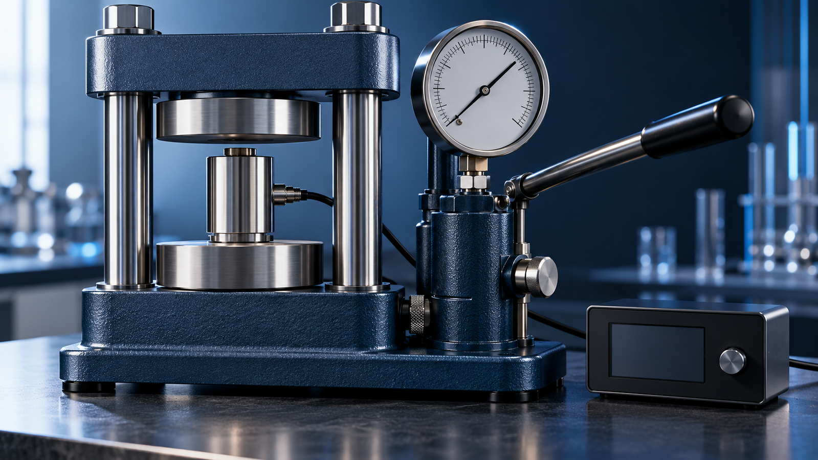
Related pages cover parts of the chain. The tonnage-to-MPa calculator converts gauge readings to force and pressure on the sample for every PressPro™ frame. The press sizing guide shows how the readout step and the low end of a range limit small dies. This page is about how far the number can be trusted, and how to find out.
1. Six words that are not the same
The international vocabulary of metrology separates ideas that everyday speech runs together.1
- Resolution depends on the display, and also on noise and friction in the instrument. A dial marked in 1 MPa steps whose pointer sticks has a coarser effective resolution than its marks.
- Accuracy is closeness to the true value. The vocabulary notes that it is not given a number; what carries a number is the measurement error (measured value minus a reference value) and the maximum permissible error a specification allows. An accuracy class is a class of instruments kept within such a limit, usually named by a number.
- Precision is closeness between repeated readings, expressed as a standard deviation or coefficient of variation. Under the same procedure, operator, instrument and place over a short period it is called repeatability. The vocabulary warns that precision is sometimes wrongly used to mean accuracy.
- Measurement uncertainty characterizes the spread of the values attributed to what is measured, based on the information used, and includes components from systematic effects. The guide to the expression of uncertainty treats an effect known only by its limits as equally likely anywhere between them;2 calibration guidelines apply this to the last digit of a display.3
- Calibration establishes the relation between a reference and the indication, with uncertainties. Adjustment changes the instrument so that it reads as prescribed, for example a zero or span adjustment. The vocabulary says the two should not be confused, and that an instrument must usually be recalibrated after an adjustment. Verification is objective evidence that an item meets specified requirements.
- Traceability means a result can be related to a reference through a documented, unbroken chain of calibrations, each adding to the uncertainty. Under the accreditation policy, such calibrations come from a national metrology institute whose service is covered by the international mutual recognition arrangement, or from a laboratory accredited for that calibration; other routes are accepted only when neither is possible.4 ISO/IEC 17025 is the standard for the competence of testing and calibration laboratories.5
2. What the gauge on a hydraulic press measures
A manual hydraulic press measures oil pressure. Force is that pressure times the area of the piston, less what the seals take. The specification of each manual frame prints a conversion factor from gauge reading to force. How that factor was derived, and whether it allows for seal friction, is not covered here.
How much the seals take depends on the seal and the conditions:
- On a test rig with a 40 mm rod at 6.3 to 16 MPa (63 to 160 bar), polyurethane rod seals produced friction forces of 535 to 1650 N. PTFE-bronze seals produced 120 to 315 N on a chromium-coated rod and up to 380 N on another coating. The polyurethane seal averaged 4.1 times the friction of the PTFE-bronze seal, and the rod coating changed friction by up to 43 %. At very low speeds, seal friction can cause stick-slip.6 For scale, by our arithmetic, 1650 N is about 0.17 t. That is a sliding rod on a rig, not a press piston holding a load. We found no study that measured seal friction in a laboratory press.
- A state manual for prestressing jacks states that jacks are in general about 95 % efficient, the efficiency changing with age and condition, and warns against calibration charts that show forces much greater than 95 % of pressure times piston area. The jack and its gauge are calibrated together with a load cell while the pressure rises; with the pressure static or falling, hysteresis inside the jack gives inaccurate loads.7
- Calibrations of hydraulic jacks against a reference load cell showed two effects. The curve from gauge reading to force did not pass through zero, and the uncertainty was 0.2 to 0.6 % of reading with a spherical cap and 0.5 to 1.2 % without one.8
- For testing machines that measure force from the hydraulic pressure at the actuator, ISO 7500-1 adds a check of the effect of the piston position on the force reading.9
So a press gauge can be within its class and the force on the die still differ from pressure times area, by an amount that can depend on the direction of loading, the piston position and the state of the seals. Only a measurement of the force itself shows it.
What the PressPro™ specifications print
| Press | Readout as printed | Also printed |
|---|---|---|
| Manual powder frames: two-column, four-column, protective | Pointer gauge with force and pressure scales, display step 1 MPa; or digital gauge, display step 0.01 t or 0.01 MPa | Force range with the gauge reading at the rated force, and a rounded conversion factor, for each frame; pressure stability within 1 MPa in 10 minutes |
| Manual infrared presses (12 and 15 T) and manual XRF presses | Pointer gauge with force and pressure scales; digital gauge optional | Force range with the gauge reading at the rated force, and a conversion factor; no display step printed |
| Electric and automatic powder presses, electric and automatic infrared presses, automatic XRF presses | Touch screen that reads force to 0.1 t, on the models whose specification prints the step | Force range with a printed lower limit; on the automatic models and the electric infrared press, pressure on the sample calculated on screen |
| Manual hot presses: heated die, dual platen, fixed upper platen | Touch-screen controller with a pressure display; a pressure gauge is listed as an option on the heated-die and manual dual-platen models | Force range; pressure on the sample calculated on screen |
| Automatic and vacuum hot presses | Touch screen | Force range with a printed lower limit; pressure on the sample calculated on screen |
As printed in the PressPro™ specifications. The accuracy class of the gauges, the accuracy of the screens, the full scale of the dials and the uncertainty of the conversion factors are not printed. These, the reading step of the hot presses and the mini infrared press are not covered here. On the manual frames the conversion factor is a rounded figure printed with the gauge reading at the rated force, for example 0 to 15 t at 30 MPa and 1 MPa = 0.5 t on the 15 T frame; the calculator lists every frame. The tool below and the calculator convert with the printed pair, the rated force divided by the gauge reading at the rated force; on the 3 T frame the rounded factor gives about 4 % less.
3. Resolution: the smallest step you can see
For a pointer gauge, resolution comes from the width of the pointer against the spacing of the marks. ISO 7500-1 and the German calibration guideline for pressure gauges recommend estimating to a half, a fifth or a tenth of a division; ISO 7500-1 allows a tenth only where the marks are at least 2.5 mm apart.9,3 For a digital display, resolution is one step of the last digit, provided the reading does not wander by more than a step with no load.3 If the reading fluctuates, ISO 7500-1 takes the resolution as half the range of fluctuation plus one step.9
How far resolution and accuracy can differ:
- A national metrology institute used a digital manometer for 0 to 70 MPa as a transfer standard in a proficiency test. It read to 0.01 kPa and was rated at 0.05 % of full scale.10 By our arithmetic the rating is ±35 kPa, 3500 times the display step.
Accuracy can also change with time and temperature:
- Industrial digital gauges used as transfer standards between institutes show six digits or more, yet two 100 MPa gauges drifted almost linearly with time over about 400 days; for some gauges the change at 100 MPa exceeded 50 Pa per day. The authors attribute the drift to slight plastic deformation of the pressure-sensing element under repeated pressurization.11
- For quartz Bourdon-type gauges held at 100 MPa for months, the long-term drift at 3 °C was much smaller than at 23 °C.12
On a press, the display step on the sample grows as the die gets smaller. On a 13 mm die, by our arithmetic, one 1 MPa division of the 15 T frame’s pointer gauge is 0.5 t and about 37 MPa on the sample; a 0.01 t digital step is about 0.7 MPa; a 0.1 t screen step about 7 MPa. The sizing guide gives the steps for every frame.
4. Accuracy classes: a percentage of the whole scale
Gauge metrology has its own standards: EN 837-1 for Bourdon-tube gauges, and ASME B40.100 for dial and digital gauges, whose public contents include a table of accuracy grades and classes. The class values are not in the public records and are not quoted here.13,14 A general rule for the accuracy classes of measuring instruments is set out by the International Organization of Legal Metrology. Where the error of an instrument does not depend much on the value measured, its maximum permissible error is stated as a percentage of a conventional value. For a scale that starts at zero, that value is the upper limit of the range. The class number is that percentage, taken from a preferred series: 1, 1.5 or 1.6, 2, 2.5, 3, 4, 5 and 6, times a power of ten.15
The consequence is arithmetic. One band, fixed in gauge units, applies across the whole dial. A worked calibration of one class 1.0 Bourdon gauge with a range up to 1.6 MPa used a single limit, ±0.016 MPa, for its whole scale.16 Applied to a press, with a class and a full scale assumed for the example only:
| 15 T frame, 30 MPa on the gauge at 15 t, 1 MPa = 0.5 t; assumed: full scale 30 MPa, class 1.6 | At 12 t | At 6 t | At 2 t |
|---|---|---|---|
| Gauge reading | 24 MPa | 12 MPa | 4 MPa |
| Permissible error, gauge (±1.6 % of 30 MPa) | ±0.48 MPa at every reading, ±0.24 t | ||
| As a share of the reading | ±2.0 % | ±4.0 % | ±12 % |
| On a 13 mm die | ±18 MPa at every reading | ||
Calculated here for an assumed class and full scale. The specification prints the gauge reading at the rated force, not the full scale of the dial or an accuracy class; this example takes the full scale as 30 MPa, as the tool below does. The band covers the gauge only, not the friction and hysteresis of the press.
A 1976 report for the US National Bureau of Standards found Bourdon gauges on the market with accuracies from 5 % down to 0.1 %, without saying on what basis, and reported that manufacturers frequently misstate performance, in both directions. It also noted that users often write purchase specifications for transducers that they cannot verify, and that information on how transducers and gauges perform over long periods was lacking.17 A class on a dial is a claim; a calibration measures the actual errors, which can then be compared with it.
5. How a calibration is done
Two kinds of calibration apply to a press. The gauge alone can be calibrated against a reference pressure standard. The force of the whole press can be checked against a reference force transducer, a load cell, placed between the platens. Only the second includes the piston and the seals. Open guidelines from European metrology bodies describe the calibration of pressure gauges and of force transducers in detail. The scheme for checking the force of a machine is in ISO 7500-1, written for testing machines.
Gauges
- Reference. The German guideline for pressure gauges recommends a reference whose uncertainty is no more than a third of the uncertainty the calibration aims for.3
- Conditions. Calibrate after the gauge has reached room temperature, between 18 and 28 °C, with the temperature held within about ±1 K during the work and recorded. Mount the gauge in the position its maker specifies.3,18
- Sequence. The guideline chooses the sequence by the uncertainty sought, as a percentage of span: at least 9 points with two or three preloadings to full scale below 0.6 %, at least 5 points with one preloading above 0.6 %, each with series of rising and falling pressure.3 The EURAMET guide’s basic procedure, for an expanded uncertainty of 0.2 % of full scale or more, uses six points in one cycle up and down, with two points measured three times for repeatability; its result is not reported below 0.2 % of full scale.18
- Timing. Readings are taken at least 30 s after a change of pressure. A Bourdon gauge waits 5 minutes at the top of its range and is tapped lightly before each reading, to reduce the effect of friction in the pointer movement. The final zero is read at least 30 s after the pressure is fully released.3,18
- History. In calibrations of high-grade hydraulic pressure transducers, the time since the previous pressure cycle changed the readings on rising pressure, by almost 35 parts per million at the lowest pressure measured; preliminary pressurization and a return to zero between points reduced the effect.19
Force on the press
- The reference. Force-proving instruments used to verify testing machines are calibrated and classified under ISO 376; ASTM E74 is the corresponding US practice for force-measuring instruments.20,21
- The scheme. ISO 7500-1 verifies a testing machine by preloading at least three times to the maximum force, then taking three series of rising force at five or more levels spaced about evenly from 20 to 100 % of the range. Below 20 % it asks for five or more forces per decade. The lower limit of a range depends on the resolution: at least 400 times the resolution for class 0.5, 200 times for class 1, 100 times for class 2 and 67 times for class 3. The zero is read about 30 s after unloading. One series of falling force is added when reversibility is to be determined.9 By our arithmetic, a 0.1 t display step therefore cannot support a class 1 lower limit below 20 t, nor class 3 below 6.7 t; a 0.01 t step, below 2 t and 0.67 t.
- Force transducers themselves are calibrated in steps such as 20, 40, 60, 80 and 100 % of range, after preloading to the maximum force for at least a minute, with at least 30 s between steps. The guideline counts the resolution twice, because an indicated force is a difference between two readings.22
- Comparisons. In two German round robins, about 40 accredited laboratories calibrated force-measuring devices on testing machines under ISO 7500-1, and their results agreed very well with those of the national metrology institute. The parts used to mount the transfer standard had a small effect, larger at 20 % of load than at full load.23
A press is not a testing machine, and these documents were not written for it. They are the closest published schemes, and the tool below follows their shape: points across the range you use, rising, repeated, with a zero.
Tablet presses show the same problem
Some pharmaceutical research presses carry their own force sensors, and those sensors are calibrated as well. Force sensors in the punch holders of a single-punch tablet machine, calibrated against a standard load cell, gave a coefficient of variation of the calibration slope of 1.46 % for the upper punch and 0.45 % for the lower.24 A commercial force and displacement instrumentation for rotary presses measured force with a deviation below 1.1 % after its calibration procedure was changed.25 Few research presses measure die-wall pressure at all, because instrumenting and calibrating it is difficult.26
6. Reading a calibration certificate
- Error and uncertainty are different columns. The error is what the instrument read minus the reference. The uncertainty is how well that error is known. The German guideline adds the two, as the expanded uncertainty plus the size of the systematic deviation, and calls the sum the error span; the EURAMET guide describes it as the largest difference to expect between a reading and the conventional true value.3,18
- Uncertainty has a floor. Whatever the calculation gives, the guideline does not state less than 0.04 % of span for its middle sequence or 0.30 % of span for its shortest one.3
- Laboratories differ. In a proficiency test, 18 accredited laboratories calibrated the same 0 to 70 MPa transfer standard at ten points, rising and falling twice. Their largest differences from the reference ranged from 0.5 to 97 kPa, and the uncertainties they declared from ±1 kPa to ±340 kPa; the organizers concluded that the participants agreed with the reference within their declared uncertainties.10 The declared uncertainty is the number to read.
- A calibration is not an adjustment. The EURAMET guide adjusts an instrument only with the client’s agreement, and a statement of compliance with a maximum permissible error is a separate, optional result.18 After an adjustment, the instrument must usually be recalibrated.1
- Look for the accreditation. The routes to traceability are given above, under Six words. Under the accreditation policy, only certificates that carry the accreditation symbol or refer to the laboratory’s accreditation benefit fully from recognition under the international arrangement.4
7. How often to calibrate
The joint guidance of the laboratory accreditation and legal metrology organizations does not recommend fixed intervals unless a normative document sets one. The first interval comes from a risk assessment. Factors include the uncertainty required, the risk of exceeding a permissible error, the maker’s recommendation, wear and drift, how much and how hard the instrument is used, the environment, data on similar devices, and the results of checks between calibrations. The interval is then reviewed with data, by calendar, by control chart, by time in use or by in-service checks.27
The German guideline for pressure gauges gives recommendations while leaving the decision to the user: 2 years for Bourdon gauges of class greater than 0.6 and 1 year for finer classes; 2 years for electric gauges above 0.5 % of span and 1 year below. It also calls for recalibration after an overload beyond the permitted limit, after a repair, and after improper handling that might affect the uncertainty.3 For prestressing jacks, the state manual requires calibration within a year or six months before use, depending on the work, and after every repair.7 Both documents tie recalibration to events, not only to the calendar.
8. When a force error matters
A force error matters through the property it changes, and how steeply a property changes with pressure differs between materials and methods:
- In a sulfide glass electrolyte, ionic conductivity rose steeply to about 10−4 S/cm at 70 MPa and then gradually to 3.1 × 10⁻⁴ S/cm at 360 MPa.28
- Another sulfide electrolyte reached 92.2 % relative density at 125 MPa and 97.8 % at 250 MPa.29
- In an XRF study of 0.1 g soil and sediment pellets pressed in a 12 mm die, loads from 4 to 40 t at a 15 s hold gave no clear change in line intensities, although pellets pressed at low load tended to crack.30
The sizing guide collects more examples. For work on the steep part of a curve, a calibrated press and a recorded reading are worth more than a finer display.
9. Gauge class and calibration check
The tool has two parts. The first shows what an accuracy class you enter means on your press and die: the permissible error in gauge units, in tonnes and in MPa on the sample, as a share of the reading across the range, and against a tolerance you set. Choose a PressPro™ manual frame, whose force range, gauge reading at the rated force and conversion factor are printed, or enter your own gauge. The full scale of the dial is not printed, so for a PressPro™ frame the tool takes the full scale as the printed gauge reading at the rated force. If your target is above the full scale, the band is not compared with your tolerance. The class is your assumption or your gauge’s certificate; the PressPro™ specifications do not print one.
The second part checks a calibration record. Enter 3 to 8 points, each with the force the press indicated and up to three readings of the reference load cell, and, if you took them, a falling-load reading and the press indication after unloading. The tool computes the error of indication and the repeatability at each point, and the reversibility and the zero where you entered them, against limits you set. Each check is its own line: Pass or Fail against your limit; Note where a limit is missing, the record has fewer than five points or a point lies below 20 % of the top point; Not checked where the record cannot support it. Each comparison uses the full-precision value; near a limit the value is shown with as many decimals as it takes to show on which side of the limit it lies, and very small readings appear in scientific notation. The limits are yours; the tool does not supply the class tables of ISO 7500-1 or EN 837-1.
10. What to record
- The readout. Gauge type, range and display step; for a manual frame, the conversion factor used.
- How the reading was taken. On rising load, after how long, and whether the gauge was tapped.
- The calibration. Date, laboratory and accreditation, reference used, points and series, errors and their uncertainty, and the zero.
- Events. Overloads, repairs, seal changes and moves of the press since the last calibration.
- The result on the sample. The force and the die area, so that the pressure can be recomputed.
The cycle guide shows how to write the force and the timing into a method line.
11. Related guides and equipment
- Tonnage-to-MPa Calculator — gauge reading, force and pressure for every frame.
- Small vs Large-Tonnage Laboratory Presses — readout steps and the low end of a range.
- How to Specify a Pellet-Press Cycle — pressure, hold and release in numbers.
- Manual vs Electric vs Automatic Laboratory Presses — what each kind of press controls.
- Manual vs Automatic XRF Pellet Presses — how finely the force is read on XRF presses.
- How to Choose a Laboratory Hydraulic Press — the whole PressPro™ range by purpose.
- Equipment: two-column, four-column and protective manual presses with pointer or digital gauges; electric and automatic powder presses with touch screens.
12. FAQ
Is a digital gauge more accurate than a pointer gauge?
It has a finer resolution, which is not the same thing. A reference-grade digital manometer read to 0.01 kPa and was rated at 0.05 % of a 70 MPa scale, that is ±35 kPa, 3500 times its display step. Accuracy is known only from a calibration. On the PressPro™ manual frames the digital gauge displays 0.01 t and the pointer gauge has 1 MPa divisions; the accuracy class of either is not printed.
What accuracy class are the PressPro™ gauges?
For the manual frames the specifications print the gauge type, the gauge reading at the rated force, a conversion factor and the display step, not an accuracy class, and this guide does not state one. If your method needs the force within a tolerance, have the press checked against a calibrated load cell.
How do I calibrate a laboratory hydraulic press?
Check the force of the whole press, not only the gauge, against a reference load cell with a traceable calibration, from an accredited laboratory or a national metrology institute, placed between the platens; in calibrations of hydraulic jacks, a spherical cap lowered the uncertainty. The published schemes for testing machines preload to the maximum force, then take several series of rising force at five or more points from about 20 to 100 % of the range, and read the zero after unloading.
How often should a press gauge be calibrated?
There is no universal interval; it is set from the uncertainty you need, drift, use and the results of checks. One German guideline recommends 2 years for Bourdon gauges of class greater than 0.6 and 1 year for finer ones, and recalibration after an overload beyond the gauge’s permitted limit, or after a repair.
Why does the reading differ going up and coming down?
Friction and hysteresis can make the reading differ between rising and falling pressure. One state manual for prestressing jacks calibrates the jack and its gauge with a load cell on rising pressure, and states that loads are inaccurate when the pressure is static or falling. Take readings the same way every time; the published schemes for testing machines use rising load.
Is the MPa on the gauge the pressure on my sample?
No. A manual press gauge reads oil pressure. Convert it to force with the frame’s printed figures, then divide by the die area. The tonnage-to-MPa calculator does both, using the rated force divided by the gauge reading at the rated force.