
Tensile testing of plastics produces a force–deformation record that is converted into method-defined stress and strain quantities. This guide explains the landmarks of the resulting curve for plastics: the initial slope that gives the modulus, the yield, the neck that forms in some ductile plastics, the strength as the selected method defines it, and the point of break. It also explains how strain is measured and why it matters, and what moves a curve between one test and the next. It adds a force screener for the step before the test and describes what the Polytevo Series Universal Testing Machine page in the Polytevo Series by ACS Material says, using only what that page says.
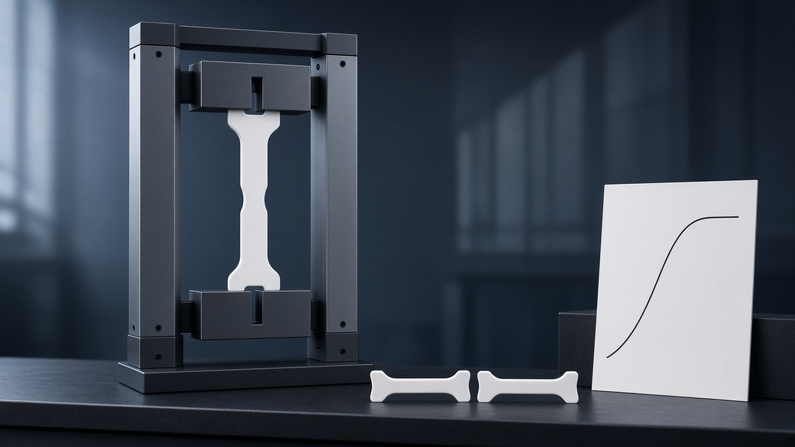
1. Tensile testing of plastics: five landmarks and one rule
A tensile test pulls a specimen at a set speed and records force against deformation; dividing force by the original cross-section gives stress, and strain is calculated from deformation and length as the selected method defines. Five landmarks are read from the curve: the modulus from the first, nearly straight part; the yield; the method-defined strength; the stress and strain at break; and, for some ductile plastics, the neck that forms after yield. For like-for-like comparisons, control and report specimen preparation, test speed, strain measurement and conditioning. Comparisons deliberately studying one of these variables can also be meaningful, but the changed condition and the purpose of the comparison must be stated. The withdrawn 1993 text cautions that results from specimens of different dimensions, or prepared under different conditions, may not be comparable.1
| Landmark | What it is, in the method definitions | What to watch |
|---|---|---|
| Modulus (Young’s modulus) | Slope of the stress/strain curve between strains of 0.05% and 0.25%; the definition does not apply to films | Use the applicable strain interval, preload/zeroing procedure and deformation measurement; the stated interval is not a universal rule for films |
| Yield stress | The stress at the yield strain, the first occurrence of strain increase without a stress increase | It may be less than the maximum attainable stress |
| Strength | The stress at the first local maximum observed during a tensile test | It may also be the stress at which the specimen yields or breaks; it need not be the highest stress reached later in the test |
| Stress and strain at break | The stress at which the specimen breaks, and the strain at break | After yielding, the strain is a method-defined nominal value based on grip displacement |
The definitions in the table are from the terms and definitions of the current ISO general-principles method, read in a public preview copy. Report strength using the selected method’s definition. Test method reference: ISO 527-1:2019 uses the first local maximum; this need not be the highest stress reached later in the test.2 Test method reference: ISO 527-2:2025 and ASTM D638-22 apply to the specimen types and conditions they cover. The ASTM method determines the tensile properties of unreinforced and reinforced plastics in the form of standard dumbbell-shaped specimens under defined conditions of pretreatment, temperature, humidity and testing machine speed.3,4
2. The elastic part: modulus, and why strain measurement decides it
The first part of the curve of many plastics is not a perfect straight line, so the modulus is defined over a fixed window of strain rather than read from a tangent by eye. Test method reference: ISO 527-1:2019 defines the tensile modulus as the slope of the stress/strain curve in the interval between strains of 0.05% and 0.25%, calculated either as the chord modulus or as the slope of a linear least-squares regression line in that interval; the definition does not apply to films.2
Modulus determination requires suitable deformation measurement over a small strain interval. Use the accuracy, preload and zeroing provisions of the selected method rather than treating historical apparatus figures as current acceptance criteria. Crosshead displacement can include deformation outside the gauge region and system movement. When this overstates the strain used in the calculation, the apparent modulus can be too low; the direction and size of the error are not universal. Test method reference: ASTM D638-22. Its scope distinguishes crosshead movement from strain between gauge marks.4
Investigate an initial toe before interpreting it: check seating, alignment, slip, zeroing and system compliance, while considering whether the curvature is material behavior. Apply a correction only when the selected method permits it and the cause is established.
Historical note (withdrawn 1993 edition, read in a public preview copy). That text asked for a testing speed giving a strain rate as near as possible to 1% of the gauge length per minute for the modulus, and for an extensometer measuring the change in gauge length with an accuracy of 1% of the relevant value or better, which for a 50 mm gauge length corresponds to ±1 µm at the modulus, with no slippage between the extensometer and the specimen. It also asked that the specimen not be substantially stressed before the test, noting that prestress can come from centering a film or from clamping pressure on less rigid materials. These are historical figures; they should not drive current apparatus selection.1
The deformation-measurement system must resolve the required gauge-length change without materially affecting the specimen. The machine standard for rubber and plastics testing machines covers the extensometer requirement. Test method reference: ISO 5893:2019, including Amendment 1:2020.5
This guide makes no statement about which extensometer any Polytevo Series machine can carry; that goes on the quotation.
3. Yield and strain localization
Yield is where the specimen stops resisting extra strain with extra stress.2 In some ductile plastics deformation then localizes in one place and a neck forms, a narrowed zone; necking is not inevitable for every material. Once deformation localizes, a gauge-length average need not represent the strain in the narrowest part of the neck.
Two reading points follow. First, after yielding, distinguish gauge-length strain from method-defined nominal strain. Use the calculation route prescribed by the selected edition; neither quantity automatically gives local strain inside a neck. Test method reference: ISO 527-1:2019 defines nominal strain as a representation of strain calculated from grip displacement and the gripping distance by one of the methods in its clause 10.2.2; it may be based on grip displacement from the beginning of the test or on the increase beyond the strain at yield when that is determined with an extensometer.2 Second, engineering stress divides the force by the original cross-section, so after necking it is not the true stress in the neck.2 G’Sell and co-workers demonstrated a video-controlled method for polyethylene and polycarbonate using the specimen’s local profile to analyze post-necking behavior.6 This illustrates one research approach; it is not a feature attributed here to the listed testing machine.
The yield stress itself depends on conditions: for injection molded polyamide 6, a strong influence of temperature and relative humidity on the yield stress and the time to failure has been reported, together with an effect of the molding conditions.7
4. Strength and break: identify the reported quantity
Report strength using the selected method’s definition. Test method reference: ISO 527-1:2019 uses the first local maximum; this need not be the highest stress reached later in the test.2 In that definition the strength may also be the stress at which the specimen yields or breaks, and the stress at yield may be less than the maximum attainable stress. A global maximum can still be reported as an explicitly identified curve quantity, but it is not a universal synonym for the method-defined strength. The same definitions treat the strain at yield, the strain at break and the strain at strength as different quantities, with nominal strain at strength and nominal strain at break defined separately.2
Two habits keep the numbers honest. State which quantity is reported: strength, stress at yield and stress at break are separate method-defined quantities that can be the same number or different ones, and stress at break is associated with specimen fracture: use the stress immediately before separation and the load drop caused by crack initiation, not an arbitrary earlier drop on the curve.2 And record where each specimen broke. Select specimen count, exclusion rules, test speeds and atmosphere from the applicable material specification and method edition. Record any speed changes, excluded specimens and replacement tests. The withdrawn 1993 text, as history only, asked for a minimum of five specimens and for specimens that broke within the shoulders to be discarded and replaced.1
5. What moves the curve from one test to the next
Five things shift a plastic’s curve, and each one belongs in the record.
- Specimen. Results from specimens of different dimensions, or prepared under different conditions, may not be comparable, as the withdrawn 1993 text cautions.1 The choice of dumbbell type for different plastics is the subject of Tensile Specimen Types: Which Dumbbell for Which Plastic?, a planned guide in this library.
- Speed. Test speed can affect the measured curve. Select test speeds from the applicable material specification and method edition, and record any speed changes. Speed is one of the factors named by the ASTM method.4
- Conditioning and atmosphere. Conditioning follows a standard atmosphere or a conditioning practice; select the atmosphere from the applicable specification and method edition.8,9
- Processing history. How a specimen was made changes it; the polyamide 6 study above is an example of molding conditions altering the yield and failure behavior.7
- Temperature. Tests at other temperatures are different set-ups with their own error sources; see the existing guides on temperature modules for universal testing machines and on in-situ tensile testing at variable temperature. That guide anatomizes the curve for metals and stages; this guide is the plastics view at room temperature.
Historical note (withdrawn 1993 edition). That text allowed different speeds for the modulus, for the properties up to yield and for the strength and maximum elongation, with separate specimens for each speed, and asked for testing in the atmosphere used for conditioning unless otherwise agreed.1 Do not assume the historical separate-specimen rule applies to every current procedure.
For how tensile testing sits beside impact and hardness testing, see Mechanical Testing of Plastics: Match the Test to the Question.
6. Before the test: how much force, and what the machine page states
Choose the applicable method and specimen first, then estimate the peak force from the original cross-section and estimated peak engineering stress. The screener below does that arithmetic and compares the result with the load-cell capacities listed on the Polytevo Series page. It is a screening aid only, and the choice of machine is the subject of How to Choose a Universal Testing Machine for Plastics.
Screening only. The screener gives a numerical comparison, not a selected configuration, and no recommendation of a load cell, frame, grip or fixture. Equality with the estimated force leaves no capacity headroom; measurement performance and the actual peak still require evaluation. Display rounding does not establish measurement precision or test validity.
If the screener does not load in your browser, the arithmetic is: force in newtons = stress in MPa × width in mm × thickness in mm; divide by the load-cell capacity in newtons to get its share.
The Polytevo Series Universal Testing Machine page describes a servo-controlled electronic testing-machine series and says one set of tensile fixtures is supplied as standard. Its listed load-cell configurations are summarized in the machine-selection guide, How to Choose a Universal Testing Machine for Plastics.
It describes testing software with dynamic test curves, including stress–strain, with data export and report printing, and a graphical processing module for re-analysis and editing after the test.
It lists constant load rate, constant deformation rate and constant displacement rate control tests.
In its “where it fits” line the page names tensile testing of metallic and non-metallic materials, including plastics. The page also says that the supplied configuration is confirmed on the quotation.
7. A short reading checklist
- Is the modulus calculated over the strain interval of the selected method, from a deformation measured as that method requires, at the speed it asks for?
- Is there a toe? Investigate it before reading a modulus: check seating, alignment, slip, zeroing and system compliance, and consider whether the curvature is material behavior. Apply a correction only when the selected method permits it and the cause is established.
- Where is the first point at which strain grows without more stress: that is the yield.
- Did a neck form, and after yielding was the strain the gauge-length strain or the method-defined nominal strain?
- Which method-defined strength is reported, and are yield stress and stress at break labelled separately?
- Were specimen count, exclusions and any replacement tests handled as the selected method requires, and recorded?
- Are the specimen, speed and conditioning written down next to the number?
The route from material to test is set out in the Lab-Scale Polymer Processing and Testing: A Workflow Guide. Handbooks of polymer testing treat each property in turn.10,11,12
8. Keep Exploring the Lab-Scale Polymer Processing Knowledge Hub
This guide belongs to the ACS Material library on lab-scale polymer processing and testing, built around the Polytevo Series by ACS Material. Start from the Lab-Scale Polymer Processing and Testing: A Workflow Guide, which places every stage of the work, from material to test, on one route. The other guides on mechanical and hardness testing are:
- Mechanical Testing of Plastics: Match the Test to the Question — which test answers which question: tensile, impact or hardness.
- How to Choose a Universal Testing Machine for Plastics — how to start from the method and specimen, estimate the force, and evaluate load-cell performance and capacity.
- Charpy vs Izod Impact Testing for Plastics — what each impact geometry loads, why the units differ, and how the notch ties the result to preparation.
- Choosing a Pendulum Energy and Calculating Impact Strength — a bounded worked example of pendulum energy shares and impact-strength arithmetic.
- Shore A vs Shore D Hardness — how the Shore scale is chosen, why there is no universal conversion, and what a constant-load test stand adds.
9. Before you request a quote
To help identify a suitable configuration, describe the tensile testing you need to run. Please tell us:
- the material and the specimen type, with the width and thickness of its narrow section;
- the estimated peak engineering stress you expect and the force it implies;
- the speeds you need, including the slow speed used for the modulus;
- how you will measure strain on the specimen;
- the test method reference you work to and whether you test only at room temperature.
Send these through Request a Quote. Specifications are as published on each product page, and final configurations are confirmed on quotation.
10. FAQ
How do I read the yield point on a plastic curve?
Test method reference: ISO 527-1:2019 defines the strain at yield as the first occurrence in a tensile test of strain increase without a stress increase, and the stress at yield as the stress at that strain; it may be less than the maximum attainable stress.2
Why is my modulus lower when I use crosshead displacement?
Crosshead displacement can include deformation outside the gauge region and system movement. When this overstates the strain used in the calculation, the apparent modulus can be too low; the direction and size of the error are not universal. Test method reference: ASTM D638-22. Its scope distinguishes crosshead movement from strain between gauge marks.4
What is the difference between strength and stress at break?
Report strength using the selected method’s definition. Test method reference: ISO 527-1:2019 defines strength using the first local maximum. Stress at break relates to specimen fracture, immediately before separation and the associated load drop. The two quantities may coincide or differ.2
Why is strain after yield called nominal?
Nominal strain is a method-defined representation based on grip displacement. It is distinct from local strain in a neck and from strain measured across gauge marks.2
Does speed change the curve?
Yes. Test speed can affect the measured curve. Use the speed sequence and specimen allocation required by the selected method; do not assume the historical separate-specimen rule applies to every current procedure.4
Does this guide cover tests at other temperatures?
No. For heating and cooling modules see the existing guide on temperature modules for universal testing machines.